


2 – Hardware Configuration
4
GPStation™ User Manual
2
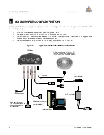
HARDWARE CONFIGURATION
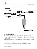
Installing the GPStation is a straightforward process. As shown in Figure 4, a minimum configuration is established with
the following set-up:
•
Set up the GPSAntenna and optional choke-ring ground plane
•
Route and connect coaxial cable between the GPSAntenna and GPStation.
•
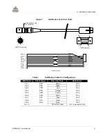
Connect an RS232 communication interface to one of the serial ports of the GPStation. The supplied null
modem cables are intended for RS232 communications only.
•
Connect the output of the power adapter to the input power jack of the GPStation.
Figure 4
Typical GPStation Installation Configuration
GPStation
Straight serial data cable
(male connector attaches to
user-supplied modem or
radio transmitter)
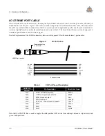
I/O strobes cable
Power cable
Automotive
cigarette-lighter
adapter
AC/DC converter
RF cable
GPSAntenna Models 501, 511 or 521
(pictured: GPSAntenna Model 501 &
Choke-ring Ground Plane Model A030)
Null-modem serial data
cable (female connector
attaches to user-supplied
operator interface)
Operator interface
Содержание GPStation
Страница 1: ...Software Rev 3 34 OM 20000014 Rev 1 0 GPStation Products NovAtel Inc GPStation TM User Manual...
Страница 33: ......
Страница 36: ...28 GPStation User Manual NOTES...
Страница 37: ...GPStation User Manual 29 NOTES...