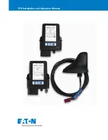
ANT-26C1GA-TBW-N and ANT-26C1GA-TBW-AN
Antennas
The compact, lightweight ANT-26C1GA-
TBW-N and ANT-26C1GA-TBW-AN
model antennas are designed for use in
any mobile application.
The ANT-26C1GA-TBW-N and ANT-
26C1GA-TBW-AN are active GPS
antennas designed to work at the L1
frequency (1575.42 ±12 MHz). These
antennas include the following features:
•
Lightning and rain protection
•
Universal single hole mounting with a threaded
connector and nut
•
Internal 33 dB amplifier
•
Designed for long cable remote installation
•
Band pass filtering
•
DC bias provided through the coaxial connector
NovAtel offers optional coaxial cables of various lengths and
models for interconnecting between the ANT-26C1GA-TBW-N
and ANT-26C1GA-TBW-AN, and our receivers.
ADDITIONAL EQUIPMENT REQUIRED
• A device with an antenna input port that both receives the RF
signal and provides 2.5 to 24.0 VDC to the antenna is required
to set up the ANT-26C1GA-TBW-N and ANT-26C1GA-TBW-
AN. (NovAtel GPS receivers provide the necessary power
through their antenna RF connectors.)
• Coaxial cable with a male TNC connector
INSTALLING THE ANTENNA
Both the input DC power and the output RF signal flow over a
single coaxial cable that is connected to the unit's TNC female
connector.
The antenna can be attached to a surface by means of a single
pre-drilled mounting hole.
Install the antenna as follows:
1. Pre-drill the connector hole on the surface, see the
Mechanical Drawings
section of this guide for details on the
connector size.
2. Put the antenna connector through the pre-drilled mounting
hole of the surface.
3. Fasten the antenna tightly to the surface using the mounting
hex nut and its lock washer.
Ref. #
Description
Ref.#
Description
1
Antenna
4
Pre-drilled mounting hole
2
Mounting surface
5
Mounting hex nut and lock washer
3
TNC connector
(24mm nut in the case of the
ANT-26C1GA-TBW-AN)
4. Remove the dust cap from the antenna’s TNC connector.
5. Attach the male TNC connector of the coaxial cable to the
antenna’s TNC connector (see the top graphic on the next
panel).
Ref. # Description
Ref. # Description
1
Antenna in place
3
TNC connector
2
Surface
4
Coaxial cable
6. Attach the other end of the coaxial cable to the antenna input
port of the receiving device, which must provide power as
detailed in the
SPECIFICATIONS
section of this guide. All
NovAtel GPS receivers provide the necessary power
through their antenna RF connectors.
The above shows an example of where the ANT-26C1GA-
TBW-N or ANT-26C1GA-TBW-AN antenna may be placed
on a vehicle (not to scale).
ANTENNA CARE
The ANT-26C1GA-TBW-N and ANT-26C1GA-TBW-AN are
designed to withstand the elements, including rain, snow, and
dust. However, to ensure your antenna performs optimally, keep
the radome clean and brush off any ice and snow. In addition,
ensure the TNC connector remains clean and dry and replace
the dust cap when a cable is not connected.
L1 ELEVATION GAIN PATTERN
USER GUIDE
2 3 5
1
4
3
2
4
1


