background image

10

Simplex 4010 NION Installation/Operation Manual  Version 2   Document 51998  Rev. A1  03/26/03

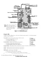
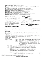
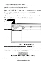
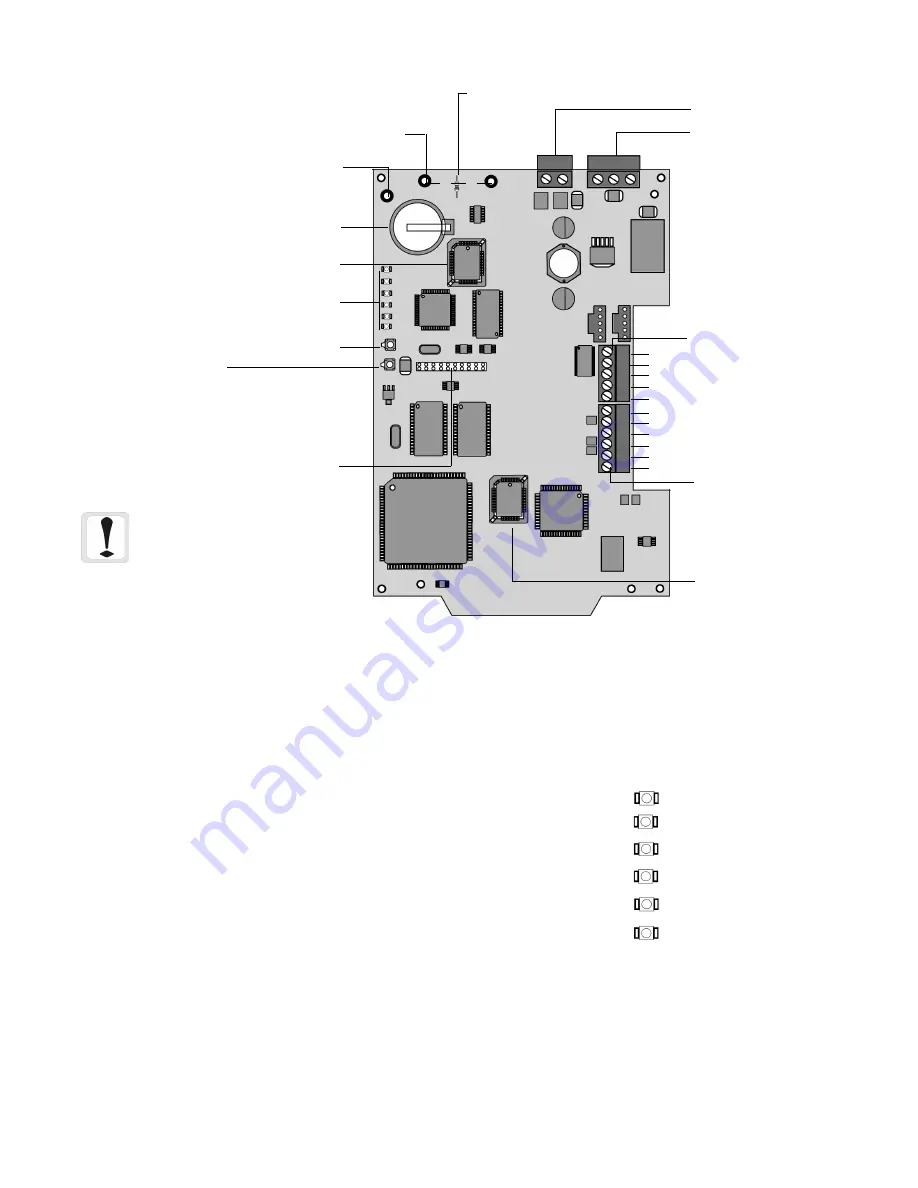
Figure 1-1:  NION-NPB Layout

Service LED

 - Indicates binding status of node on Echelon network.

Slow blink indicates NION not bound.

Off indicates NION bound.

On indicates nonrecoverable error.

Network Status

 - Indicates status of Echelon network interface.

Slow blink indicates network operation normal.

Off indicates network interface not functioning.

Fast blink indicates a network communication error.

Network Packet

 - Blinks briefly each time a data packet is received or transmitted on the Echelon network.

Serial 2

 - Application specific indicator of serial port activity (port 2).

Serial 1

 - Application specific indicator of serial port activity (port 1).

NION Status

 - Indicates status of the NION.

Rapid blinking indicates proper NION operation.

On or Off indicates critical error and that the NION is not functioning.

Diagnostic LEDs

The NION contains six LEDs which are used as aids in diagnosing proper operation.  The following paragraph
details the function of each LED.

Service

Service

Service

Service

Service

Network Status

Network Status

Network Status

Network Status

Network Status

Network P

Network P

Network P

Network P

Network Packet

acket

acket

acket

acket

Serial 2

Serial 2

Serial 2

Serial 2

Serial 2

Serial 1

Serial 1

Serial 1

Serial 1

Serial 1

NION Status

NION Status

NION Status

NION Status

NION Status

3V  Lithium

3V  Lithium

3V  Lithium

3V  Lithium

3V  Lithium

Battery

Battery

Battery

Battery

Battery

J1 Header for Echelon

J1 Header for Echelon

J1 Header for Echelon

J1 Header for Echelon

J1 Header for Echelon

Network T

Network T

Network T

Network T

Network Transceiver

ransceiver

ransceiver

ransceiver

ransceiver

Application PLCC

Application PLCC

Application PLCC

Application PLCC

Application PLCC

SW2 Network

SW2 Network

SW2 Network

SW2 Network

SW2 Network

Binding Button

Binding Button

Binding Button

Binding Button

Binding Button

SW1 Reset

SW1 Reset

SW1 Reset

SW1 Reset

SW1 Reset

Button

Button

Button

Button

Button

Network Communication PLCC

Network Communication PLCC

Network Communication PLCC

Network Communication PLCC

Network Communication PLCC

SMX T

SMX T

SMX T

SMX T

SMX Transceiver

ransceiver

ransceiver

ransceiver

ransceiver

Standoff Mounting

Standoff Mounting

Standoff Mounting

Standoff Mounting

Standoff Mounting

Holes

Holes

Holes

Holes

Holes

Chassis

Chassis

Chassis

Chassis

Chassis
Ground

Ground

Ground

Ground

Ground

Diagnostic LEDS

Diagnostic LEDS

Diagnostic LEDS

Diagnostic LEDS

Diagnostic LEDS

R72 Cut T

R72 Cut T

R72 Cut T

R72 Cut T

R72 Cut To Disable Ground

o Disable Ground

o Disable Ground

o Disable Ground

o Disable Ground

Fault Detection

Fault Detection

Fault Detection

Fault Detection

Fault Detection

GND    +24VDC

PPPPPower Input (TB5)

ower Input (TB5)

ower Input (TB5)

ower Input (TB5)

ower Input (TB5)

TB6-Relay Output

TB6-Relay Output

TB6-Relay Output

TB6-Relay Output

TB6-Relay Output

U24

U24

U24

U24

U24

BT1

BT1

BT1

BT1

BT1

U6

U6

U6

U6

U6

TB7 - RS-485 Interface

TB7 - RS-485 Interface

TB7 - RS-485 Interface

TB7 - RS-485 Interface

TB7 - RS-485 Interface

NO

NO

NO

NO

NOTE

TE

TE

TE

TE:  The NION-

:  The NION-

:  The NION-

:  The NION-

:  The NION-

Simplex 4010 does not

Simplex 4010 does not

Simplex 4010 does not

Simplex 4010 does not

Simplex 4010 does not
use this connection.

use this connection.

use this connection.

use this connection.

use this connection.

TB1- 5-

TB1- 5-

TB1- 5-

TB1- 5-

TB1- 5-W

W

W

W

Wire Serial

ire Serial

ire Serial

ire Serial

ire Serial

Interface A

Interface A

Interface A

Interface A

Interface A

RX
GND

CTS

RTS

TX

+5VDC

GND

RX+

RX-

TX+

TX-

NOTE:  There is a paper insulator
between the battery and the
battery clip installed at the factory
to keep the battery charged.
Remove the insulator before
applying power.

Technical Manuals Online! - http://www.tech-man.com

firealarmresources.com

Содержание UniNet 2000 Simplex 4010 NION

Страница 1: ...x 4010 NION A1 51998 A1 ECN 02 298 Document 51998 03 26 03 Rev UniNet 2000 Simplex 4010 NION Installation and Operation Manual Version 2 Technical Manuals Online http www tech man com firealarmresourc...

Страница 2: ...2 Simplex 4010 NION Installation Operation Manual Version 2 Document 51998 Rev A1 03 26 03 This page intentionally left blank Technical Manuals Online http www tech man com firealarmresources com...

Страница 3: ...ns caused by escaping gas improper storage of flammable mate rials etc Heat detectors do not sense particles of combustion and alarm only when heat on their sensors increases at a predetermined rate o...

Страница 4: ...efore making modifica tions verify that they will not interfere with battery transformer and printed circuit board location Do not tighten screw terminals more than 9 in lbs Over tightening may damage...

Страница 5: ...4010 NION Architecture 15 Figure 2 2 Simplex 4010 NION to Simplex 4010 9811 Serial Connections 16 2 2 Simplex 4010 NION Enclosure and Mounting 17 Figure 2 3 Simplex 4010 NION Power Connection 17 Figu...

Страница 6: ...6 Simplex 4010 NION Installation Operation Manual Version 2 Document 51998 Rev A1 03 26 03 Technical Manuals Online http www tech man com firealarmresources com...

Страница 7: ...originating from a Simplex 4010 panel UniNet consists of graphical workstations monitoring and controlling local or remote twisted pair or fiber optic networks Remote network monitoring is achieved t...

Страница 8: ...8 Simplex 4010 NION Installation Operation Manual Version 2 Document 51998 Rev A1 03 26 03 This page intentionally left blank Technical Manuals Online http www tech man com firealarmresources com...

Страница 9: ...technologies The Simplex 4010 NION provides transparent or interpreted communications between the workstation and control panel The NION connects a LonWorks FT 10 or fiber optic network to a fire ala...

Страница 10: ...SW2 Network SW2 Network SW2 Network SW2 Network SW2 Network Binding Button Binding Button Binding Button Binding Button Binding Button SW1 Reset SW1 Reset SW1 Reset SW1 Reset SW1 Reset Button Button B...

Страница 11: ...ween monitored equipment and the network Connections One twisted pair of wires or dedicated fiber optic cable is used for data transmission in the UniNet network The wire must be Twisted pair cable UL...

Страница 12: ...transformer isolated making all network communication immune to ground fault conditions Therefore no ground fault supervision of the Echelon network is required or provided FTXC PCA and FTXC PCB Netwo...

Страница 13: ...when an error occurs This suppresses noise propagation throughout the network Figure 1 5 Sample Style 7 Networks For more information about Style 7 network configuration refer to the Local Area Server...

Страница 14: ...r allow runs of up to 12db of attenuation between each node with up to 64 nodes per segment DFXC DFXC DFXC DFXC DFXC Dual Fiber Optic Transceiver Figure 1 6 FOXC PCA and DFXC PCA Fiber Optic Network T...

Страница 15: ...ON NION NION NION NION NION EchelonT EchelonT EchelonT EchelonT EchelonTo Other Nodes o Other Nodes o Other Nodes o Other Nodes o Other Nodes Ethernet T Ethernet T Ethernet T Ethernet T Ethernet To Ot...

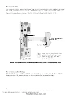
Страница 16: ...rial Connections The Simplex 4010 NION requires that a Simplex model 4010 9811 dual EIA 232 card be installed in the Simplex 4010 FACP The NION communicates to the 4010 FACP through serial port P6 onb...

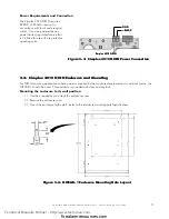
Страница 17: ...er 3 Mount the enclosure to the wall Refer to the enclosure mounting hole layout below Figure 2 4 NISCAB 1 Enclosure Mounting Hole Layout Power Requirements and Connection The Simplex 4010 NION requir...

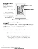
Страница 18: ...ting Studs w Standoffs Mounting Studs w Standoffs Mounting Studs w Standoffs Mounting Studs w Standoffs Figure 2 5 Installing the NION in a NISCAB 1 Mounting NION boards within the enclosure When inst...

Страница 19: ...CHANGE button on the form This will cause a dialogue box to be displayed with the names of all available configuration files Select SX4010 cfg and then click the OPEN button Finally click DONE to end...

Страница 20: ...Simplex 4010 Explorer The Simplex 4010 NION is easily configured to communicate with a Simplex 4010 FACP via the Simplex 4010 Explorer Only an operator with administrator privileges can access configu...

Страница 21: ...ces or labels are added or changed a Panel Learn must be performed again Figure 3 4 Duplicate Device Labels The Simplex 4010 devices must not have any duplicate device labels If duplicate device label...

Страница 22: ...ppress Psuedo Points box in the data display See figure 3 6 UL Functionality This option will be displayed only if the current operator is logged in as an administrator This option must always be chec...

Страница 23: ...M M M M M Mounting 17 N N N N N NFN Explorer Overview 19 NION NPB 9 NISCAB 1 17 P P P P P Power Requirements 11 R R R R R Required Equipment 9 Index S S S S S Serial Communication Settings 16 Serial C...

Страница 24: ...o NOTIFIER 12 Clintonville Road Northford Connecticut 06472 1653 This writing constitutes the only warranty made by NOTIFIER with respect to its products NOTIFIER does not represent that its products...

Отзывы: