N500-53-00 1 I56-1230-06R
Notifier, 12 Clintonville Rd, Northford, CT 06472, (203) 484-7161
FSP-751 and FSP-751T Intelligent Photoelectronic Smoke Sensors
Installation and Maintenance Instructions
This sensor must be installed in compliance with the control panel system installation manual. The installation must meet the requirements of the Authority
Having Jurisdiction (AHJ). Sensors offer maximum performance when installed in compliance with the National Fire Protection Association (NFPA); see NFPA
72.
GENERAL DESCRIPTION
Model FSP-751 and FSP-751T are intelligent sensors that combine a state-of-the-art photoelectronic sensing chamber with communications. The FSP-751T
adds thermal sensors that will alarm at a fixed temperature of 135°F. These sensors are designed to provide open area protection and are intended for use with
compatible control panels only.
Two LEDs on each sensor light to provide a local, visible sensor indication. Remote LED annunciator capability is available as an optional accessory (Part No.
RA400Z).
Notifier panels offer different features sets across different models. As a result, certain features of the FSP-751 or FSP-751T may be available on some control
panels, but not on others. The possible features available in the FSP-751 and FSP-751T, if supported by the control unit are:
1. The panel controls the LED operation on the sensor. Operational modes are RED blink, RED continuous, GREEN blink, and off.
2. The remote output may be synchronized to the LED operation or controlled independent of the LEDs.
Please refer to the operation manual for the UL listed control unit for specific operation of the FSP-751 and FSP-751T.
SPECIFICATIONS
Operating Voltage Range:
15 to 32 VDC
Standby Current:
300
µ
A
@ 24 VDC (one
communication every 5
seconds with LED blink enabled)
Max. Alarm Current (LED on):
6.5 mA @ 24 VDC
Operating Humidity Range:
10% to 93% Relative Humidity, noncondensing
Operating Temperature Range:
0° to 49°C (32° to 120°F); FSP-751
Operating Temperature Range:
0° to 38°C (32° to 100°F); FSP-751T
Height:
1.7 inches (43 mm) installed in B710LP Base
Diameter:
6.1 inches (155 mm) installed in B710LP Base
4.1 inches (104 mm) installed in B501 Base
Weight:
3.6 oz. (102 g)
SPACING
Notifier recommends spacing sensors in compliance with NFPA 72. In low air
flow applications with smooth ceilings, space sensors 30 feet apart. For specific
information regarding sensor spacing, placement, and special applications, refer
to NFPA 72 or Notifier’s
System Smoke Detector Application Guide
, available at
no charge from Notifier.
Duct Applications: FSP-751 and FSP-751T are listed for use in ducts.
See Duct Applications Guide A05-1004 for details on pendant mount applications.
NOTE:
These products are not listed for use inside duct smoke detectors.
WIRING INSTRUCTIONS
All wiring must be installed in compliance with the National Electrical Code, applicable
local codes, and any special requirements of the Authority Having Jurisdiction.
Proper wire gauges should be used. The installation wires should be color-coded to
limit wiring mistakes and ease system troubleshooting. Improper connections will prevent
a system from respondingproperly in the event of a fire.
Disconnect power from the communication line before installing sensors.
All wiring must conform to applicable local codes, ordinances, and regulations.
1. Wire the sensor base (supplied separately) per the wiring diagram (Figure 1).
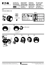
2. Set the desired address on the sensor address switches.
NOTE:
Some panels support extended addressing. In order to set the sensor above address 99 on compatible
systems, carefully remove the stop on the upper rotary switch with thumb as shown in Figure 2.
3. Install the sensor into the sensor base. Push the sensor into the base while turning it clockwise to secure it in place.
4. After all sensors have been installed, apply power to the control unit and activate the communication line.
5. Test the sensor(s) as described in the
TESTING
section of this manual.
TESTING
Before testing, notify the proper authorities that the system is undergoing maintenance, and will temporarily be out of
service. Disable the system to prevent unwanted alarms.
All sensors must be tested after installation and periodically thereafter. Testing methods must satisfy the Authority Having
Jurisdiction (AHJ). Sensors offer maximum performance when tested and maintained in compliance with NFPA 72. The sen-
sor can be tested in the following ways:
3
2
1
3
2
1
+
–
–
+
OPTIONAL RETURN LOOP
REMOTE ANNUNCIATOR
+
–
CAUTION
Dust covers provide limited protection against airborne dust particles during shipping. Dust covers must be
removed before the sensors can sense smoke. Remove sensors prior to heavy remodeling or construction.
Figure 1. Wiring Diagram
0
1
2
3
4
5
6
7
8 9 10
11
12
13
14
15
0
1
2
3
4
5
6
7
8 9
Sperre, Ausbruchstelle
Figure 2. Rotary Address Switches
LED STATUS
INDICATORS
TEST
MAGNET
PAINTED
SURFACE
PAINTED
SURFACE
MAGNET TEST
MARKER
D
O
N
O
T
P
A
IN
T
TEST
MAGNET
Figure 3.
Caution:
Do Not Loop Wire Under Terminal 1 or 2.
Break Wire Run To Provide Supervision of Connections.
www.PDF-Zoo.com