06.02.2014
LineTroll
110Tµr
User Manual
Страница 1: ...LineTroll 110T r User Manual...
Страница 2: ...sing a healthy line 7 4 2 Connecting a faulty line while the indicator is activated 7 4 3 Transient faults 8 4 4 Fused lines 8 4 5 Multiple faults 8 4 6 Capacitive discharges 9 4 7 PROGRAMMING 10 5 MA...
Страница 3: ...ermanent fault and 1 regular Green LED for transient faults The LED flash can be seen within 100 200 metres distance The lens of the indicator allows for uniform 360 degrees monitoring LINETROLL 110E...
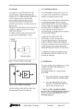
Страница 4: ...ush current it s di dt sensor is blocked for 5 sec upon energising of a line While the blocking time elapses the line current can stabilise so as not to cause triggering of the di dt sensor A fault du...
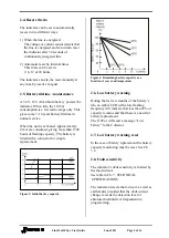
Страница 5: ...d giving more than 1500 hours of flashing capacity The battery is fitted with a connector for simple replacement Figure 3 Initial battery capacity Figure 4 Remaining battery capacity as a function of...
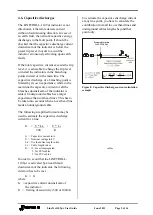
Страница 6: ...ce there may be an indication in a branch due to a non permanent fault while another branch without an indicator installed may be faulty yet remain unidentified as such Near line points with sectional...
Страница 7: ...blocking time a shows the sequence when a fault occurs less than 5 sec after line has been energised No Indication If upon re energising of a line the unit is already indicating due to a previous fau...
Страница 8: ...tion within 5 sec followed by an automatic reclosing causing a fuse operation the indication starts but will reset after 30 sec If the automatic reset is switched off the indicator will continue flash...
Страница 9: ...wnstream of the indicator is added Underground cables have larger capacitance than overhead lines This has to be taken into account when an overhead line feeds an underground cable The following simpl...
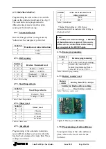
Страница 10: ...et 4 7 5 Auto Reset Programming of the automatic indication reset AR If enables reset occurs when the line has been energised for more than 30 sec voltage or current Switch 7 Auto reset on return of v...
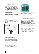
Страница 11: ...y is replaced with a new battery the battery monitoring must be reset With the battery disconnected reset can be done setting Rotary switch to position see figure 11b while at the same time powering t...
Страница 12: ...Flashing 1500 flashing hours Battery replacement normally every 7 10 years Indication 1 Super intensive red Flash every 3 sec 10 sec after 12 hours 1 green LED for transient fault 1 amber Yellow LED f...
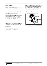
Страница 13: ...e indicators at strategic points along the line 9 1 Before mounting Make sure the indicator is programmed see 4 7 Programming and battery connected before mounting on the line 9 2 Live line mounting b...
Страница 14: ...capacity remains and that there is a need for a battery replacement The LT 110T r will in addition transmit a Low Battery message to the Collector Programming Open the indicator by unscrewing the top...
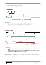
Страница 15: ...transient fault Permanent fault GREEN RED Comments The Permanent Fault indication red LEDs is delayed 70 sec to verify a permanent fault Both red and green LED s will flash on permanent faults until r...
Страница 16: ...equence 1 2 3 4 Amber 5 Green RESET sequence If the line is energised the GREEN LED only flashes for 3 sec If the line is de energised line the RED LED s only flashes for 3 sec 3 s 3 s 2s Test sequenc...