SPOOL TORCH: Installation and Operation
May 25, 2022
Page 13
User Manual No: OM-10
4
A EN
4.04
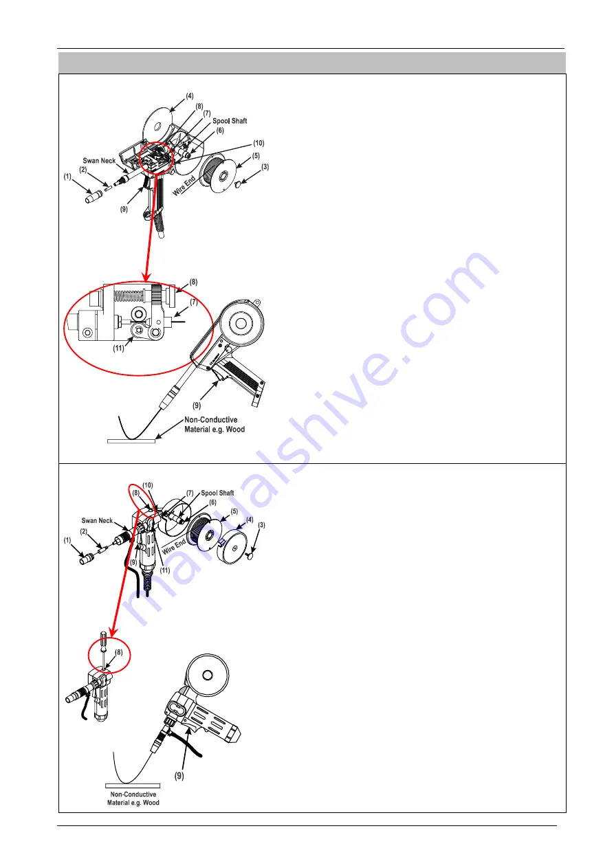
SPOOL TORCH: Install Welding Wire Spool Then Threading the Welding Wire
MODEL: QLBF-200 III
a) Disconnect Power to the MIG/MAG equipment.
b) Ensure the Drive Roll is marked with the same size as the
Welding Wire
you are
about to fit in the Spool Torch.
c) Lift the
Spool Cover (4)
by pressing
Press Button (10).
d) Unscrew
Nozzle (1),
Contact Tip (2)
, and
Locking Screw (3)
.
e) Put the
Welding Wire Spool (5)
on the
Spool Shaft
to check the
Welding Wire
Spool (5)
has some friction with the
Spool Shaft
. If no friction, then adjust the
Hub
Tension Nut (6)
so some friction is felt between the
Welding Wire Spool (5)
and the
Spool Shaft
. Remove the
Welding Wire Spool (5)
from the
Spool Shaft
.
f) Rotate the
Pressure Arm Bolt (8)
clockwise to release the tension on the
Pressure
Roll Bearing (11)
.
g) Take the Wire End from the top of the
Welding Wire Spool (5).
CAUTION:
Hold the
Wire End
tightly to stop it from unravelling.
h) Feed the
Wire End
into the
Inlet Guide (7)
then push the
Welding Wire
75 mm (3
in.) out past the
Swan Neck
.
i) Secure the
Welding Wire Spool (5)
using
Locking Screw (3)
then screw the
Pres-
sure Arm Bolt (8)
counter clockwise to put some tension on the
Wire End
.
j) Flip the
Spool Cover (4)
over to cover the
Welding Wire Spool (5)
, then
fit the
Con-
tact Tip (2)
, and
Nozzle (1)
on the Spool Torch.
k) Before you start welding, test the Pressure Arm force to the Drive Roll is sufficient to
feed the welding wire.
i. Connect MIG/MAG Spool Torch as per Section 4.03 then connect Power to the
MIG/MAG equipment.
ii. Point the Spool Torch at 60 degree and 100mm (4 in.) from a flat non-conductive
material, e.g. wood, on the floor.
iii. Depress
Torch Trigger Switch (9)
to feed
Welding Wire
on to a flat non-conduc-
tive material, e.g. wood.
iv. If
Welding Wire
slips on the Drive Roll (welding wire does not feed constantly
from Torch) then adjust
Pressure Arm Bolt (8)
.
v. Rotate
Pressure Arm Bolt (8)
by:
- Rotating in a counter-clockwise direction reduces Pressure Arm force to the
Drive Roll. Reduced Pressure Arm force on the Drive Roll causes the
Welding
Wire
to slip on the Drive Roll and can produce an inconsistent welding.
- Clockwise direction increases the Pressure Arm force to the Drive Roll. Increased
Pressure Arm force on the Drive Roll can cause the
Welding Wire
to deform pro-
ducing metal fragments which clogs the Liner in the
Swan Neck
and can produce
poor wire feedability.
MODEL: QLBF-185
a) Disconnect Power to the MIG/MAG equipment.
b) Ensure the Drive Roll is marked with the same size as the
Welding Wire
you are
about to fit in the Spool Torch.
c) Unscrew
Nozzle (1)
,
Contact Tip (2)
, and
Locking Screw (3)
then remove
Spool
Cover (4)
.
d) Put the
Welding Wire Spool (5)
on the
Spool Shaft
to check the
Welding Wire
Spool (5)
has some friction with the
Spool Shaft
. If no friction, then adjust the
Hub
Tension Nut (6)
so some friction is felt between the
Welding Wire Spool (5)
and the
Spool Shaft
. Remove the
Welding Wire Spool (5)
from the
Spool Shaft
.
e) Take the Wire End from the top of the
Welding Wire Spool (5),
CAUTION:
Hold the
Wire End
tightly to stop it from unravelling,
then feed it into the
Inlet Guide (7)
while pushing down on the red
Pressure Roll Release Lever (10)
then push the
Welding Wire
75 mm (3 in.) out past the
Swan Neck
.
f) Fit the
Spool Cover (4)
,
Locking Screw (3)
,
Contact Tip (2)
, and
Nozzle (1)
on the
Spool Torch.
g) Before you start welding, test the Pressure Arm force to the Drive Roll is sufficient to feed the
welding wire.
i. Connect MIG/MAG Spool Torch as per Section 4.03 then connect Power to the MIG/MAG
equipment.
ii. Point the Spool Torch at 60 degree and 100mm (4 in.) from a flat non-conductive material,
e.g. wood, on the floor.
iii. Depress
Torch Trigger Switch (9)
to feed
Welding Wire
on to the flat non-conductive ma-
terial, e.g. wood.
iv. If
Welding Wire
slips on the Drive Roll (
Welding Wire
does not feed constantly from
Torch) then adjust
Pressure Arm Screw (8)
.
v. Adjust the
Pressure Arm Screw (8)
using a screwdriver:
- Rotating in a clockwise direction reduces Pressure Arm force to the Drive Roll. Reduced
Pressure Arm force on the Drive Roll causes the
Welding Wire
to slip on the Drive Roll
and can produce an inconsistent welding.
- Counter-clockwise direction increases Pressure Arm force to the Drive Roll. Increased
Pressure Arm force on the Drive Roll can cause the
Welding Wire
to deform producing
metal fragments which clogs the Liner in the
Swan Neck
and can produce poor wire feed-
ability.


