Chapter 20 — Meridian Mail Compact Option installation and maintenance
Page 241 of 536
Option 11C Compact
Planning, Installation, Fault Clearing and CCBR Guide
Assigning the dataport locations
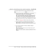
To assign dataport locations to your system, follow these steps.
Step
Action
1
From the previous procedure.
Select Yes, then press <Return>.
Result The dataport configuration table is displayed. The following
shows the default settings for a basic Meridian Mail Compact Option
system.
Node Card Type Port 1 Port 2 Port 3 Port 4
1 1 ESBC CONSOLE CLS1 DIAGNOST
------------------------------------------------------------
Please assign the data port locations.
Select operation : Display
The following shows the default settings for a Meridian Mail Compact
Option system running HVS.
Node Card Type Port 1 Port 2 Port 3 Port 4
1 1 ESBC CONSOLE CLS1
1 4 RSM MOD0131 PRT0132 PMS0143 PMS0143
------------------------------------------------------------
Please assign the data port locations.
Select operation : Display
Meridian Mail Compact Option systems can have up to six data ports:
the first two are reserved for the system administration terminal and the
link to the Meridian 1 switch, the third is reserved for the RS-232 port on
the faceplate of the Meridian Mail Compact Option CPU card, and the
remaining three are the three ports available on the RSM Assembly
Module, if one is installed.
On basic systems, the RS-232 port on the faceplate of the Meridian
Mail Compact Option CPU card is generally used to connect a
diagnostic terminal to Meridian Mail. On HVS systems, the software
considers this port a virtual port on the RSM Assembly Module and
allows you to configure it for a second GAC terminal.
Содержание Meridian Meridian 1
Страница 3: ...553 3121 210 Standard 3 0 January 1999 ...
Страница 17: ...xiv Contents 553 3121 210 Standard 3 0 January 1999 ...
Страница 89: ...Page 70 of 536 Chapter 6 Bracing cabinets against earthquakes 553 3121 210 Standard 3 0 January 1999 ...
Страница 97: ...Page 78 of 536 Chapter 8 Installing a new system 553 3121 210 Standard 3 0 January 1999 ...
Страница 107: ...Page 88 of 536 Chapter 10 Installing the system ground 553 3121 210 Standard 3 0 January 1999 ...
Страница 113: ...Page 94 of 536 Chapter 11 Installing the power supply 553 3121 210 Standard 3 0 January 1999 ...
Страница 125: ...Page 106 of 536 Chapter 12 Adding an expansion cabinet 553 3121 210 Standard 3 0 January 1999 ...
Страница 139: ...Page 120 of 536 Chapter 13 Installing the circuit cards 553 3121 210 Standard 3 0 January 1999 ...
Страница 157: ...Page 138 of 536 Chapter 15 Installing and connecting SDI and Ethernet ports 553 3121 210 Standard 3 0 January 1999 ...
Страница 175: ...Page 156 of 536 Chapter 16 Starting up and testing the system 553 3121 210 Standard 3 0 January 1999 ...
Страница 209: ...Page 190 of 536 Chapter 18 Connecting the trunks 553 3121 210 Standard 3 0 January 1999 ...
Страница 323: ...Page 304 of 536 Chapter 21 Installing Hospitality 553 3121 210 Standard 3 0 January 1999 ...
Страница 419: ...Page 400 of 536 Chapter 23 Pre programmed data 553 3121 210 Standard 3 0 January 1999 ...
Страница 455: ...Page 436 of 536 Chapter 24 Changing pre programmed data 553 3121 210 Standard 3 0 January 1999 ...
Страница 555: ...Page 536 of 536 Chapter 25 Fault locating and clearing 553 3121 210 Standard 3 0 January 1999 ...


