


Carrier Remote IPE column installation
87
Procedure 13
Installing cards into the Remote IPE module
Step
Action
1
Set the DIP switches on the NT7R52 Remote Carrier Interface
card to specify the carrier type (T1 or E1), the distance to the
first repeater, the MMI terminal baud rate, and the system
monitor address.
The DIP switch setting depends on the physical system
configuration.
2
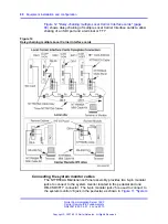
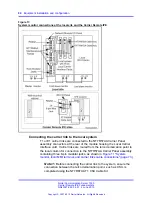
Verify that SW1 position 2 is set to ON to specify the remote site.
Note:
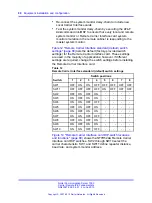
Figure 14 "Remote Carrier Interface card DIP-switch
locations and functions" (page 89)
shows the location of
the DIP switches and their functions. Switches 2, 3, and 4
determine if carrier 0 is a T1 or an E1 link, switches 4, 6, and
7 determine if carrier 1 is a T1 or an E1 link, and switches 8,
9, and 10 determine if carrier 2 is a T1 of an E1 link. All three
carrier links must be of the same type, for example, T1 or E1.
DIP switches S 1 and SW11 define parameter listed in the
table in
Figure 14 "Remote Carrier Interface card DIP-switch
locations and functions" (page 89)
. Correspondingly,
9 "Local Carrier Interface card DIP-switch positions and
function" (page 67)
, shows the Local Carrier Interface card
DIP switches SW1 through SW11 and their functions. Refer
to
Figure 9 "Local Carrier Interface card DIP-switch positions
for DIP switch settings for the Local
Carrier Interface card.
3
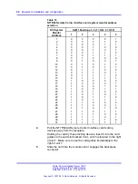
Determine the system monitor address for each remote site by
setting SW11 positions 1-5 on the Remote Carrier Interface card.
Before selecting the address, determine the available system
monitor addresses, as follows:
•
Execute the
STAT XSM
command in LD 37 to poll all system
monitors. Correct any problems.
•
Determine available system monitor addresses to be
assigned to the Remote IPE module or the wall-mounted
Carrier Remote IPE cabinet.
•
Set master system monitor slave polling address range to
cover the new Carrier Remote IPE system monitor address.
•
Set Remote Carrier Interface card SW 11 positions 1-5 for
the new system monitor address.
Nortel Communication Server 1000
Carrier Remote IPE Fundamentals
NN43021-555 04.01
4 June 2010
Copyright © 2007-2010 Nortel Networks. All Rights Reserved.
.
Содержание Communication Server 100
Страница 213: ......


