Installation / 31
P0941568 01
Modular ICS 5.0 Companion Installer Guide
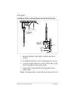
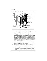
5. Mount the base station onto the bracket, snapping it into
position.
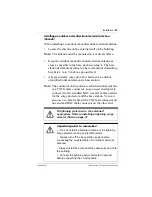
6. Connect the power RJ11 jumper lead to the RJ11 jacks on
the termination board and the base station.
7. For plug-top power supplies only, connect the power
supply connector to the base station power connector.
Make sure the base station is powered by a class 2 plug-top
power source only.
8. Record the associated ICS port number in the space
provided on the printed label affixed on the lower right
corner of the mounting bracket.
Include the labeling information for each Companion base
station on the completed installation floor plans.
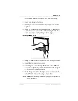
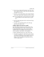
9. Slide the cover onto the bracket, using the guide to position
it properly. Snap it into place.
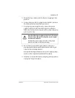
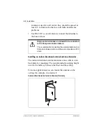
Inserting the power supply connector in the wrong
direction may damage the plug-top power supply
and the base stations.
Position the power supply connector in the proper
direction and push it into place securely.
Содержание Modular ICS 5.0 Companion
Страница 2: ......
Страница 130: ...124 Glossary Modular ICS 5 0 Companion Installer Guide P0941568 01 ...

