


© Norsat International Inc.
(“Norsat”) All Rights Reserved
2021-04-23 039092 Rev C
15
with pins and requires the mating connector to be a plug with sockets (e.g Amphenol
®
PT06E-12-4S-SR).
A range of plug-compatible mating connectors may be used to add options to the plug such as right-angle,
stress relief clamp, metal color/finish, etc. Please contact the connector manufacturer for more information
and/or refer to the Amphenol
®
catalog 12-070. Ensure the supply cable is capable of supplying at least
300W of power (for 25W ATOM Ka) or 600W of power (for 50W ATOM Ka).
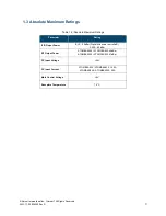
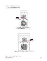
DC Unit J3 Connector Pinouts
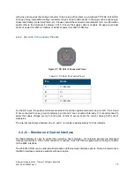
Figure 2-7: DC Unit J3 Connector Pinout
Table 2-1: DC Unit J3 Connector Pinout
Pin
Name
A
V-/Ground
B
V+
C
V+
D
V-/Ground
For the DC input, the positive terminals are pins B/C and the negative terminals are pins A/D. Pins A and
D are connected to case ground internally; pins B and C are connected internally. It is recommended to
apply the supply voltage evenly to both pairs of pins to evenly share the current among both sets of
wires/pins.
The internal capacitance between the V+ and V- terminals is approximately 120 microfarads.
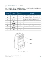
2.4 J2
– Monitor and Control Interface
The M&C interface is used to control the unit with a host computer. All on-board sensors are accessed
through this interface. Use of this connection is optional. Each ATOM is supplied with a mating connector
for the M&C interface.
The 25-50W ATOM can be ordered with standard or Ethernet web interface options. Table 2-2 summarizes
the M&C interface protocols available with each option.
A
B
D
C


