background image


ATOM Ku GaN 20-40-80W BUC & 

SSPA 


052910 


32 

052910_rA - Operator Manual for ATOM Ku 

GaN Series 20-40-80W 


Section 2.11 
F

AULT 

I

NDICATOR 

/


LED 

D

ESCRIPTION  OF 

O

PERATION


Norsat Ku GaN 20W, 40W and 80W are equipped in a general purpose Status LED signal. This signal is 
intended to give a visual aid of the status of the device.  

M

ODES  OF 

O

PERATION


The Status LED in the Front Panel of the devices will show  three different statuses: 

STARTING, FAULT, 

and NO FAULTS. 

S

TARTING WITH 

N

F

AULTS  

S

TATUS


The Status LED will flash once for a lapse of approximately one second every time the power of the device 
in recycled to OFF and set back to ON. If no fault is detected in the device at the Power Up, the led will g o 
to OFF afterwards settling in that state.  

F

AULT AND 

N

F

AULTS  


In the event of a 

PLL Fault, 

an

 Over Input Fault, 

a

 Power Fault, 

or an 

Over Temperature Fault

, the 

Status LED will turn on independently of whether the MUTE STATE of the device is UNMUTED or 
MUTED due Hardware or Software. If the cause of the fault disappears the Status LED will turn OFF until 
any of the Faults shows again independently of the MUTE STATE. 

Commented [WP5]: 

Update to Ku GaN 

Содержание ATOM Series

Страница 1: ...2910 1 052910_rA Operator Manual for ATOM Ku GaN Series 20 40 80W ATOM Ku GaN 20 40 80W BUC SSPA Operator s Manual Document Number 052910 Revision A Norsat International Inc 110 4020 Viking Way Richmond British Columbia Canada V6V 2L4 ...

Страница 2: ...roducts to improve reliability function or design Norsat does not assume any liability arising out of the application or use of any product or circuit described herein Norsat does not convey any license under its patent rights or the rights of others TECHNICAL SUPPORT This manual provides engineers with information necessary to operate the applicable system Technical support is available from Nors...

Страница 3: ...s 20 40 80W REVISION HISTORY Rev CO Reason for Change Reviewed By Author Date mm dd yyyy A CN 1023 Initial Release SL FY TK 03 20 2020 Non Digital Approval Only if required Scan this page with signature and attach to Change Order if this section used Approver Name Approver Signature Date ...

Страница 4: ...PERFORMING FIRMWARE UPDATE 15 SECTION 2 6 J4 DC POWER 19 SECTION 2 7 SERIAL PORT SOFTWARE INTERFACE 20 Controller Responses 20 Message Definitions 20 Command Response 22 Mute Logic 23 SECTION 2 8 ETHERNET INTERFACE ATOMCONTROL WEB INTERFACE ATOM SNMP AGENT 25 Default IP Address 25 Changing the ATOM Series Device s IP Address 25 Recovering the ATOM Series Device s IP Address 26 Accessing ATOMContro...

Страница 5: ...2 9 Progress Bar Indicates Firmware Update Progress 17 Figure 2 10 Confirmation of Updated Firmware Version 18 Figure 2 11 DC Unit J4 Connector Pinout 19 Figure 2 12 Setup Serial Port 20 Figure 2 13 Command getident Ref Only 20 Figure 2 14 Command getstatus 21 Figure 2 15 Command getfaults 21 Figure 2 16 Command setmute mute unit 22 Figure 2 17 Command setmute unmute unit 22 Figure 2 18 The Mute L...

Страница 6: ... ATOM SSPAs and BUCs with the following marketing numbers ATOMBKUGxxx 020 040 080W ATOMSKUGxxx 020 040 080W SSPA SOLID STATE POWER AMPLIFIER If this unit is a SSPA the RF input signal is amplified to the specified power BUC BLOCK UP CONVERTER AND AMPLIFIER If this unit is a BUC the IF input signal is upconverted to Ku Band RF frequencies and then amplified to the specified power ...

Страница 7: ...TRICAL INTERFACE M C Connector a ten pin connector is used to interface with a host computer See Section 2 3 J2 Monitor and Control Interface for detailed description of the pinouts Ethernet Connector a six pin connector is used to update the firmware and communicate with the BUC SSPA through the web based ATOMControl interface See Section 2 4 J3 Ethernet port for detailed description of pinouts P...

Страница 8: ...n RF load 100W min or connected to the feed of a terminal Do not obstruct the RF output or feed output with any body part W A R N I N G Do not allow equipment to be standing in water While the BUC SSPA is designed to be used outdoors the equipment is not designed to operate in standing water Failure to follow this precaution could result in electric shock and injury to persons C A U T I O N Do not...

Страница 9: ...e The interface for these connectors is detailed in this document On the input side there are the following connectors J1 IF or RF Input N Type Jack J2 Ten pin circular shell size 12 Amphenol connector for M C RS232 RS485 J3 Six pin circular shell size 10 Amphenol connector for Ethernet J4 Four pin circular shell size 12 Amphenol DC power connector J6 Ground terminal Figure 2 1 Input Connections f...

Страница 10: ...or ATOM Ku GaN Series 20 40 80W On the output side there is one connector J5 WR75 waveguide RF output J5 Option WR62 waveguide RF output for wide band J5 Figure 2 2 Standard Waveguide WR75 Output for ATOM Ku GaN Unit Commented WP1 Please add wide band WR62 flange output ...

Страница 11: ...10 MHz reference are both traveling on this line The connector is DC blocked Do not exceed 50VDC on this port The 10 MHz signal should be accurate within 1ppm otherwise the BUC may have difficulty phase locking to it The 10 MHz should be free of sideband spurs particularly close in under 100 kHz as these may also cause failure to lock Power level of the 10 MHz reference signal should be 5 dBm SSPA...

Страница 12: ...connector is Amphenol part number PT06E 12 10S 476 A range of compatible part numbers for the mating connector may be used to add options to the plug such as right angle stress relief clamp metal color finish etc Please contact the connector manufacturer for more information and or refer to Amphenol catalog 12 070 Figure 2 3 J2 M C Connector Pin Arrangement Table 2 1 summarizes the various pinout ...

Страница 13: ...olarity Mute Line Bias Sample Input 1 Sample Mute State 1 Sample Input 2 Sample Mute State 2 Sample Input 3 Sample Mute State 3 Default 0V Unmute Pull Down 0V Unmuted 5V Muted Floating Unmuted Sample 1 0V Unmute Pull Up 0V Unmuted 5V Muted Floating Muted Sample 2 5V Unmute Pull Down 0V Muted 5V Unmuted Floating Muted Sample 3 5V Unmute Pull Up 0V Muted 5V Unmuted Floating Unmuted Note that the ATO...

Страница 14: ...er PT06E 10 6S 476 A range of compatible part numbers for the mating connector may be used to add options to the plug such as right angle stress relief clamp metal color finish etc Please contact the connector manufacturer for more information and or refer to Amphenol catalog 12 070 Figure 2 4 J3 Ethernet Connector Pin Arrangement Table 2 3 J3 Pinouts for Ethernet Port Connector Pin Standard Confi...

Страница 15: ...tab contains controls for performing a firmware update All of the firmware version will be displayed once the BUC is communicated with ATOMControl and being initialized ATOMControl is a program designed for monitoring and controlling Norsat s ATOM Series of BUCs and SSPAs This software and user manual are available on the Norsat ATOM Series website Figure 2 5 Firmware Version from ATOMControl FW U...

Страница 16: ...ware image file from the Image File Selection Dialog for updating on the ATOM Ku GaN device Click Open to confirm the selection Figure 2 7 Image File Selection Dialog Figure 2 8 shows the confirmation of the selected firmware image file and the availability of the Start Update function Click the Start Update button to start the firmware update process ...

Страница 17: ...0W Figure 2 8 Image File Confirmation and Start Update Function Figure 2 9 shows the firmware update is in progress firmware update process takes about one minute Do not switch off the ATOM series device while firmware update is in progress Figure 2 9 Progress Bar Indicates Firmware Update Progress ...

Страница 18: ...ries 20 40 80W When the firmware update process is complete the Atom device automatically resets and reconnect to ATOMControl The status shows the new version of the firmware is running on the ATOM device as shown below in Figure 2 10 Figure 2 10 Confirmation of Updated Firmware Version ...

Страница 19: ...nnector This connector is a MIL C 26482 Series 1 receptacle shell size 12 4 pin Amphenol 93 533723 04P The connector is a receptacle with pins and requires the mating connector to be a plug with sockets e g Amphenol PT06E 12 4S 476 A range of plug compatible mating connectors may be used to add options to the plug such as right angle stress relief clamp metal color finish etc Please contact the co...

Страница 20: ...p bits 1 flow control none Figure 2 12 Setup Serial Port CONTROLLER RESPONSES The unit will only generate messages in response to a command Each command received will result in a single message reply which may simply be an Acknowledge message In general command responses are returned immediately though the precise command response delay varies slightly based on the specific command MESSAGE DEFINIT...

Страница 21: ...he specific type has occurred and a value of 1 indicates a fault has occurred The mute status is controlled by mute on fault setting When mute on fault is active and the device is physically muted a value of 0 indicates that the muting was not caused by a fault A value of 1 indicates that the muting was caused by a fault When mute on fault is inactive mute status always shows a value of 0 Figure 2...

Страница 22: ...tfaults message Figure 2 16 Command setmute mute unit Figure 2 17 Command setmute unmute unit COMMAND RESPONSE The CLI operates on a command response format Each time a command is entered a response will be displayed If a command executed correctly an ok along with potential parameters and values will be displayed Otherwise err will be displayed along with a description of the error The potential ...

Страница 23: ...p Over Temperature Fault pll PLL Fault power Power Fault CR LF where Mute Fault 0 unit unmuted or 1 unit muted Over Temperature Fault 0 temp ok or 1 error over temp condition exists PLL Fault 0 pll ok or 1 error pll loss of lock resettempfault None CR LF ok CR LF CR LF err CR LF when system temperature is above trip point setmute cmd 0 1 0 unmute 1 mute CR LF ok CR LF getmuteonfault None CR LF ok ...

Страница 24: ...PA 052910 24 052910_rA Operator Manual for ATOM Ku GaN Series 20 40 80W 3 A fault condition exists For mute priorities software precedes over faults and hardware and faults precedes over hardware Figure 2 18 The Mute Logic Diagram ...

Страница 25: ...efault the subnet mask is 255 255 255 0 Ensure the computer s IP Address is on the same logical network and subnet as the ATOM unit e g 192 168 77 XXX where XXX is any number except 30 CHANGING THE ATOM SERIES DEVICE S IP ADDRESS The Ethernet settings for an ATOM series device can be changed using the device s Command Line Interface Ensure that a serial connection has been made to the device refer...

Страница 26: ...al program or Norsat s ATOMControl software to send the appropriate command to the device To get the device s Ethernet settings getip CR The corresponding response CR LF ok ip IP Address mask Subnet Mask gw Gateway Address CR LF where IP Address is the device s IP Address Subnet Mask is the device s Subnet Mask and Gateway Address is the device s Gateway Address Example command and corresponding r...

Страница 27: ...The default SNMP settings are as follows SNMP service port 161 SNMP trap port 162 SNMP read write community public SNMP manager IP address 192 168 77 255 255 on the 4th part of the address means to broadcast on the 192 168 77 subnet and allow any host in the subnet to access the SNMP agent SNMP traps on fault enabled To obtain status for and enable disable SNMP service and trap Enabling SNMP servi...

Страница 28: ...rent community string setsnmpcommunity value string CR where the SNMP community string is between 4 and 10 characters SNMP agent uses the same community string for both read and write Set the NMS SNMP server to the same community string to access the Atom SNMP agent Example commands and corresponding responses setsnmpcommunity value AtomBUC CR CR LF ok CR LF getsnmpcommunity CR CR LF ok community ...

Страница 29: ...emp pll power overinput 0 1 CR where 1 turns the option on and 0 turns the option off overtemp sends traps when an over temperature fault is detected on the ATOM device pll sends traps when PLL lock is lost on the ATOM device power sends traps when irregularities associated with power is detected on the ATOM device overinput sends traps when an over input fault from the IF is detected on the ATOM ...

Страница 30: ...GaN 20 40 80W BUC SSPA 052910 30 052910_rA Operator Manual for ATOM Ku GaN Series 20 40 80W setsnmptraponfault all 1 CR CR LF ok CR LF getsnmptrapoonfault CR CR LF ok overtemp 1 pll 1 power 1 overinput 1 CR LF ...

Страница 31: ...is will provide extra protection against water ingress at the flange to flange interface The unit is supplied with screws four 6 32x3 8 it is the user s responsibility to ensure that the appropriate screw length is used There should be at least 4 threads of engagement 0 1 with the holes in the waveguide flange The waveguide output port should not be relied upon to act as a mechanical support for t...

Страница 32: ...TS STATUS The Status LED will flash once for a lapse of approximately one second every time the power of the device in recycled to OFF and set back to ON If no fault is detected in the device at the Power Up the led will go to OFF afterwards settling in that state FAULT AND NO FAULTS In the event of a PLL Fault an Over Input Fault a Power Fault or an Over Temperature Fault the Status LED will turn...

Страница 33: ...ironment and is sealed to prevent water ingress Ensure the waveguide and or feed connected to J5 are also sealed with gaskets to prevent water ingress Section 3 2 FANS BASEPLATE COOLING The standard ATOM configuration employs an integrated radiator and IP55 fans to cool the unit A minimum clearance of 1 inch must be maintained around the air intake and exhaust during use The fans are a field repla...

Страница 34: ...arizes general specifications applicable to most 20 40 80W ATOM Ku GaN units Please refer to the specific ATOM datasheet available on the Norsat website for complete unit specifications Table 3 1 General 20 40 80W ATOM Ku GaN Specifications Parameter Specifications RF Power Output 20W 43dBm 40W 46dBm 80W 49dBm Gain min 70 dB typ 65 dB min 75 dB max Operating Temperature with fans 40 C to 60 C Stor...

Страница 35: ...for a period of three 3 year from the ship date unless otherwise stated in the Offer Terms and Conditions The warranty does not cover units that have been damaged through improper use or physical damage e g dropped units been modified altered or repaired by the user the security label s removed or damaged the serial number label removed or altered To obtain warranty repair service please contact N...

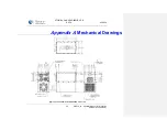
Страница 36: ...ATOM Ku GaN 20 40 80W BUC SSPA 052910 36 052910_rA Operator Manual for ATOM Ku GaN Series 20 40 80W Appendix A Mechanical Drawings Figure A 3 1 20 40 80W Ku GaN BUC SSPA Fan Cooled ...

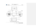
Страница 37: ...ATOM Ku GaN 20 40 80W BUC SSPA 052910 37 052910_rA Operator Manual for ATOM Ku GaN Series 20 40 80W Figure A 3 2 20 40 80W Ku GaN BUC SSPA Baseplate Cooled ...

Страница 38: ...Definition BUC Block Upconverter AMP Amplifier C Celsius CR Carriage Return character ASCII dBm Decibel milliwatts DC Direct Current ESD Electrostatic Discharge freq Frequency GHz Gigahertz GND Ground IF Intermediate Frequency kHz kilohertz LF Line Feed character ASCII M C Monitor and Control MHz Megahertz mm Millimeter N A Not Applicable ppm Pulses per minute RF Radio Frequency RX Receive SSPA So...

Отзывы: