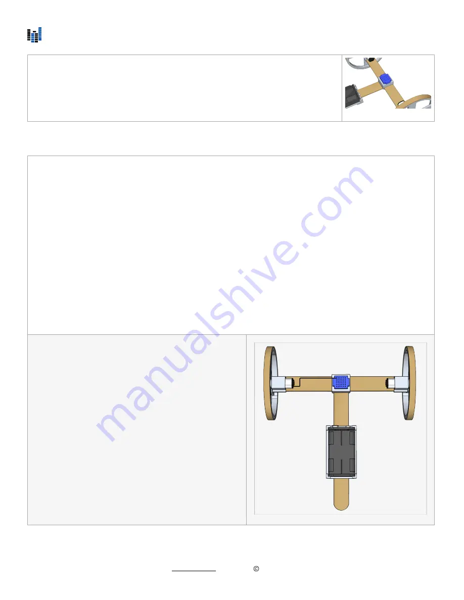
v. Wire the ScioBot 1.0
Step 2:
Press the mini breadboard into the the top of the T-Connector. Make sure the side with the
25 holes is facing up. Check to make sure the wires from the battery holder can be
plugged into the breadboard. If they are too far away, rotate the battery holder so that the
wires are pointing towards the breadboard.
Introduction:
When following these wiring instructions, do not worry which wires you use. You will
not
harm your ScioBot by
connecting wires incorrectly. (Just don’t connect the positive and negative leads from the battery connector! This will
short out your batteries and drain them almost instantly) Once all the wires are connected and the ScioBot is powered
on, it may not behave as expected if the wires are not connected in the required configuration for forward travel. This
is ok because there are actually many di
ff
erent wiring configurations you can use to make your ScioBot behave in
di
ff
erent ways. You may have actually already configured your ScioBot in an advanced configuration! If you want to
ensure you have the correct wire polarity, refer to the Expert Tip in Section III before continuing. We will learn how to
adjust the wiring configuration once we have completed the wiring section!
Breadboard:
Every row of holes in the breadboard going from the left to right can be considered a component rail. What this means
is anything connected to a given row will be connected to all other components connected in that same row.
DC Motors:
A DC motor will rotate in a direction respective to the direction of current applied. It does not matter which motor lead
gets the positive current and which gets negative current, only that one is positive, and the other is negative. By
reversing the flow of current, the DC motor will rotate in the opposite direction. You can reverse the flow of current by
switching the position of the motor leads in the breadboard.
Step 1:
Connect one lead from the left motor to the top row on the
breadboard.
©
Nonscio 2020
4


