background image

Issue 1 11/2005

COMPANY CONFIDENTIAL

Copyright © 2005 Nokia. All Rights Reserved.

Nokia Customer Care

5 - Disassembly Instructions

Содержание RM-127

Страница 1: ...Issue 1 11 2005 COMPANY CONFIDENTIAL Copyright 2005 Nokia All Rights Reserved Nokia Customer Care 5 Disassembly Instructions ...

Страница 2: ...RM 127 Nokia Customer Care 5 Disassembly Instructions 2 COMPANY CONFIDENTIAL Issue 1 11 2005 Copyright 2005 Nokia All Rights Reserved This page intentionally blank ...

Страница 3: ...DENTIAL 3 Copyright 2005 Nokia All Rights Reserved RM 127 5 Disassembly Instructions Nokia Customer Care Table of Contents Page No Disassembly Instructions 5 General requirements 5 Detailed disassembly instructions 6 Reassembly 13 ...

Страница 4: ...RM 127 Nokia Customer Care 5 Disassembly Instructions 4 COMPANY CONFIDENTIAL Issue 1 11 2005 Copyright 2005 Nokia All Rights Reserved This page intentionally blank ...

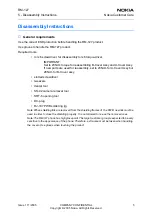
Страница 5: ... Assy If new parts are used for reassembly set to 23Ncm for A Cover Assy but 28Ncm for B Cover assy slotted screwdriver tweezers dental tool SS 42 camera removal tool SRT 6 opening tool DC plug RJ 107 PWB soldering jig Note When shielding lids are removed from the shielding frames of the PWB new lids must be used in order to close the shielding properly It is not allowed to re use the removed ones...

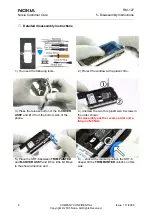
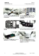
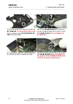
Страница 6: ... plastic film 3 Press the release button of the C COVER ASSY and lift it from the bottom side of the phone 4 Unscrew the two Torx plus size 6 screws in the order shown For Assembly use the reverse order and a torque of 23Ncm 5 Place the SRT 6 between TRIM PAINTED and B COVER ASSY and lift it a little bit Move to the shown direction and 6 stick at the marked position the SRT 6 deeper till the TRIM ...

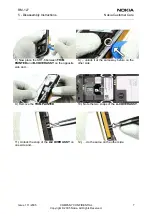
Страница 7: ... Nokia Customer Care 7 Now place the SRT 6 between TRIM PAINTED and B COVER ASSY on the opposite side and 8 unlock it at the same way before on the other side 9 Remove the TRIM PAINTED 10 Note the two snaps of the A COVER ASSY 11 Unlock the snap of the A COVER ASSY on one side and 12 do the same on the other side ...

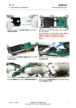
Страница 8: ...your fingers and bent the A COVER ASSY slightly Now press the KEYMAT at the shown side out of the A COVER ASSY 15 Note the four snaps of the UI PWB HOLDER 16 Use a slotted screwdriver and release all four snaps by sticking carefully in the holes 17 Remove the UI PWB Holder including the UI MODULE from the Engine Module 18 Hold the UI PWB HOLDER with your fin gers Press the snaps down with the twee...

Страница 9: ...ews in the order shown For assembly use the reverse order IMPOR TANT Torque for used B Cover Assy 23Ncm Torque for new B Cover Assy 28Ncm 21 Remove the ENGINE MODULE from the B COVER ASSY 22 Use the SRT 6 to open the connector of the LCD MODULE 23 Separate the UI SHIELD ASSY including the LCD MODULE from the ENGINE MODULE 24 Bent the UI SHIELD ASSY slightly and press out the LCD MODULE Prevent def...

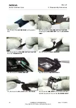
Страница 10: ...with a plastic film 26 Remove the VOLUME KEY ACTUATOR including the VOLUME KEY from the B COVER ASSY 27 Separate the VOLUME KEY ACTUATOR from the VOLUME KEY 28 Remove the IRDA WINDOW 29 Remove the VIBRA MOTOR 30 Remove the MICROPHONE 31 Remove the DC JACK with a DC PLUG 32 Press the SIM GRIP to the shown direction and lift one side of it out of the B COVER ASSY ...

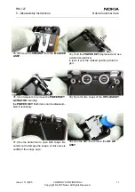
Страница 11: ...ssed and use a slotted screwdriver to lever it over the marked position white fin ger 35 Use tweezers to remove the POWER KEY ACTUATOR including the POWER KEY Both items can be disassem bled if necessary 36 Note the two snaps of the IHF LID ASSY 37 Use the dental tool to open both snaps Be careful not to damage the snaps A click noise is audible if the snaps open 38 Use the SRT 6 to remove the IHF...

Страница 12: ...ways a new IHF SPEAKER ADHE SIVE when assembling 40 Put the ENGINE MODULE to the module jig Use a slotted screwdriver as a lever to open the CAMERA SHIELD For assembling not the guide pin 41 Stick the SS 42 into the marked positions of the camera connector to release the snaps 42 Use the back side of the SS 42 to remove the CAMERA MODULE For assembling not the guide pin of the CAMERA MODULE and sl...

Страница 13: ... 2005 COMPANY CONFIDENTIAL 13 Copyright 2005 Nokia All Rights Reserved RM 127 5 Disassembly Instructions Nokia Customer Care Reassembly Reassembly should be in reverse order to disassembly unless otherwise stated ...

Страница 14: ...RM 127 Nokia Customer Care 5 Disassembly Instructions 14 COMPANY CONFIDENTIAL Issue 1 11 2005 Copyright 2005 Nokia All Rights Reserved This page intentionally blank ...

Отзывы: