background image

Disable equipment

558

WebEML User Manual


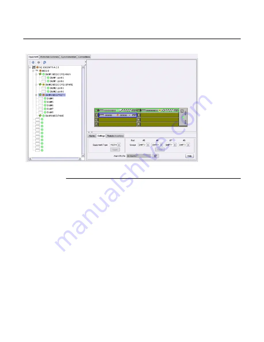
Figure 372

Disabled MPT ODU from P8ETH

To disable an MPT access card

1. Select 

MSS-n/Slot#

 (slot 3 through 8) in the resource tree area where the MPT 

Access card will be disabled. The selected slot will highlight in blue. This 
selection also highlights the selected slot in blue on the graphical representation 
of the MSS shelf in the resource list area. See 

Figure 373

.

Release 7.0.0 3DB 19286 ACAA Issue 01

Содержание 9500 MPR

Страница 1: ...Nokia Proprietary and confidential Use pursuant to applicable agreements 9500 Microwave Packet Radio WebEML User Manual WebEML User Manual Release 7 0 0 3DB 19286 ACAA Issue 01 ...

Страница 2: ...ducts for any such application without the prior written consent of Nokia shall be at the customer s sole risk The customer hereby agrees to defend and hold Nokia harmless from any claims for loss cost damage expense or liability that may arise out of or in connection with the use sale license or other distribution of the products in such applications This document may contain information regardin...

Страница 3: ...e to radio communications Operation of this equipment in a residential area is likely to cause harmful interference in which case users will be required to correct the interference at their own expense Release notes describing revisions to this software may impact operations described in this manual This transfer of commodities technology or software if from the United States is an export in accor...

Страница 4: ...4 WebEML User Manual Release 7 0 0 3DB 19286 ACAA Issue 01 ...

Страница 5: ... 1 3 3 Moving mechanical parts 51 1 3 3 1 Labeling 51 1 3 3 2 Safety instructions 51 1 3 4 Equipment connection to earth 52 1 3 4 1 Labeling 52 1 3 4 2 Safety instructions 52 1 3 5 Heat radiating mechanical parts 52 1 3 5 1 Labeling 52 1 3 5 2 Safety instructions 53 1 3 6 Microwave radiations EMF norms 53 1 3 6 1 Safety instructions 53 1 4 Electromagnetic compatibility EMC norms 54 1 4 1 Cables 55...

Страница 6: ...t provisioning 73 6 1 Purpose 73 6 2 Procedure 73 7 High level procedure for Ethernet deprovisioning 77 7 1 Purpose 77 7 2 Procedure 77 8 High level procedure for Ethernet LAG provisioning 81 8 1 Purpose 81 8 2 Procedure 81 9 High level procedure for SDH provisioning 83 9 1 Purpose 83 9 2 Procedure 83 10 High level procedure for SDH deprovisioning 85 10 1 Purpose 85 10 2 Procedure 85 11 High level...

Страница 7: ...2 16 Administer external alarm points on an MSS 1 or Enhanced Fan card 117 16 1 Purpose 117 16 2 Prerequisites 117 16 3 Overview 117 16 4 Procedure 118 17 Administer In Band TMN VLAN port 121 17 1 Purpose 121 17 2 Overview 121 17 3 Procedures 124 18 Administer network configuration 129 18 1 Purpose 129 18 2 Overview 129 18 2 1 OSPF area 130 18 3 Procedures 132 19 Administer QoS configuration 147 1...

Страница 8: ...2 10 Latitude and Longitude 177 22 3 Procedures 177 23 Administer VLAN configuration 185 23 1 Purpose 185 23 2 Overview 185 23 2 1 802 1D MAC address bridge 185 23 2 2 802 1Q virtual bridge 185 23 2 3 802 1ad Provider Bridge 186 23 2 3 1 Ethernet frames processing 187 23 2 3 2 Cross connected flows processing 187 23 3 Procedures 188 24 Local access control management 199 24 1 Purpose 199 24 2 Over...

Страница 9: ... Change password 243 31 1 Purpose 243 31 2 General 243 31 3 Procedure 244 System information 247 32 View alarms 249 32 1 Purpose 249 32 2 General 249 32 2 1 Alarm manager 249 32 2 2 Web Server 251 32 3 Procedures 252 33 View abnormal condition list 261 33 1 Purpose 261 33 2 General 261 33 3 Procedure 261 34 View NE Inventory data 263 34 1 Purpose 263 34 2 General 263 34 3 Procedures 264 35 Downloa...

Страница 10: ...40 Administer Ethernet Ring Protection ERP 293 40 1 Purpose 293 40 2 General 293 40 2 1 Modify ERP provisioning 293 40 2 2 Delete ring topology 295 40 2 3 Delete ERP Instance 295 40 3 Procedures 295 41 Administer L1 L2 radio and L2 Ethernet LAG ports 305 41 1 Purpose 305 41 2 General 305 41 2 1 Provider bridge parameters 305 41 3 Procedures 307 42 Administer synchronization 333 42 1 Purpose 333 42...

Страница 11: ...0 43 14 1 Single right click icon 360 43 14 2 Double click on the line 360 43 14 3 Double right click on the line 361 43 15 Procedures 362 44 Deprovision cross connections 383 44 1 Purpose 383 44 2 General 383 44 3 Procedures 383 45 Provision port segregation connectivity 393 45 1 Purpose 393 45 2 General 393 45 3 Procedure 398 46 Configure AUX cross connections ETSI market only 403 46 1 Purpose 4...

Страница 12: ... 51 1 Purpose 477 51 2 Prerequisites 477 51 3 Procedures 477 52 Disable equipment 523 52 1 Purpose 523 52 2 Prerequisite 523 52 3 Procedures 523 53 Provision Ethernet Ring Protection ERP 565 53 1 Purpose 565 53 2 Prerequisites 565 53 3 General 566 53 4 Procedures 566 54 Upgrade a Ring to R5 1 0 software 579 54 1 Purpose 579 54 2 General 579 54 3 Procedure 580 55 Provision cross connections in a mi...

Страница 13: ...9 2 1 Monodirectional links 786 59 3 Prerequisites 787 59 4 Procedures 787 60 Perform IPv6 pre provisioning 883 60 1 Purpose 883 60 2 General 883 60 3 Procedure 883 61 Use the Provisioning Tool 889 61 1 Purpose 889 61 2 General 889 61 2 1 Provisioning tool screens 889 61 3 Procedures 890 62 Apply a configuration using the Web Server 945 62 1 Purpose 945 62 2 General 945 62 3 Procedure 945 Equipmen...

Страница 14: ...Switching 1001 68 4 Hot StandBy protection switching 1001 68 5 Protection switching schemes per configurations 1001 68 6 Protection switching commands 1002 68 7 Procedures 1003 69 Perform radio power measurements 1023 69 1 Purpose 1023 69 2 Procedure 1023 70 Radio Facing Circuit Loopback 1029 70 1 Purpose 1029 70 1 1 General 1029 70 2 Procedures 1030 71 RF Core Facing Loopback 1033 71 1 Purpose 10...

Страница 15: ... 74 2 General 1057 74 3 Radio profile 1057 74 4 Procedures 1058 75 Upgrade MPT HL to MPT HL L1 LAG port 1061 75 1 Purpose 1061 75 2 General 1061 75 3 Procedure 1063 76 Upgrade MPT ODU to MPT ODU L1 LAG port 1067 76 1 Purpose 1067 76 2 General 1067 76 3 Procedure 1068 77 Perform Tx Diversity Antenna operations 1071 77 1 Purpose 1071 77 2 Procedures 1071 Release 7 0 0 3DB 19286 ACAA Issue 01 ...

Страница 16: ...16 WebEML User Manual Release 7 0 0 3DB 19286 ACAA Issue 01 ...

Страница 17: ... 230 38 Perform debug functions using the Web Server 285 Table 5 Association of the GExx in the command output and the NE port 286 59 Configure radio parameters 785 Table 6 Configurations in monodirectional links 786 68 Perform protection switching 999 Table 7 Command priority list 1002 75 Upgrade MPT HL to MPT HL L1 LAG port 1061 Table 8 MPT HL L1 LAG bandwidth per service type 1062 Release 7 0 0...

Страница 18: ...18 WebEML User Manual Release 7 0 0 3DB 19286 ACAA Issue 01 ...

Страница 19: ...Figure 19 Acknowledgment of authorization 98 Figure 20 JUSM CT 9500 MPR main screen MSS 8 shelf 99 Figure 21 JUSM CT 9500 MPR main screen MSS 4 shelf 100 Figure 22 JUSM 9500 MPR main screen MSS 1 shelf 101 Figure 23 JUSM 9500 MPR main screen MSS O shelf 102 Figure 24 Close JUSM 9500 MPR main screen 102 Figure 25 Close NEtO Servers Manager window 103 Figure 26 9500 MPR web interface log in webpage ...

Страница 20: ...guration window IPv6 142 Figure 53 Activate IPv6 stack main menu bar path 143 Figure 54 Activate IPv6 stack warning 144 Figure 55 Routing Information main menu bar path 144 Figure 56 IP Routing Information window 145 19 Administer QoS configuration 147 Figure 57 QoS Configuration icon 148 Figure 58 QoS Configuration tool 149 Figure 59 Provision Queue Scheduler algorithm 150 Figure 60 Provisioned Q...

Страница 21: ...tion window with CorEvo card in use 190 Figure 91 VLAN Configuration provisioned 802 1D 191 Figure 92 VLAN Configuration provisioned 802 1Q 192 Figure 93 VLAN Configuration provisioned 802 1ad 192 Figure 94 Create VLAN window 193 Figure 95 New VLAN created 194 Figure 96 Edit VLAN window 194 Figure 97 Filter VLAN configuration table 196 Figure 98 VLAN Configuration table filtered 196 24 Local acces...

Страница 22: ... with added user 233 Figure 128 USM User management main menu bar path 234 Figure 129 USM Users Management window 234 Figure 130 USM user cloning panel 235 Figure 131 USM Users Management window with added user 236 Figure 132 Profile management window 237 Figure 133 Delete user window 237 Figure 134 Profile management window with user deleted 238 Figure 135 Profile management window 239 Figure 136...

Страница 23: ...161 Ethernet Protection Ring Configuration View 296 Figure 162 Modify ERP Instance with ERP Instance enabled 298 Figure 163 Modify ERP Instance with ERP Instance disabled 299 Figure 164 Add VLAN IDs to ERP Instance 301 Figure 165 Delete VLAN IDs from ERP Instance 302 41 Administer L1 L2 radio and L2 Ethernet LAG ports 305 Figure 166 LAG Configuration icon 307 Figure 167 LAG Configuration tool 308 ...

Страница 24: ...98 Configuration Cross Connection window 363 Figure 199 PDH RADIO Cross Connection 364 Figure 200 PDH to Ethernet Cross Connection 365 Figure 201 SDH RADIO Cross Connection 367 Figure 202 SDH RING Cross Connection 368 Figure 203 SDH to LAG configuration dialog 369 Figure 204 Completed SDH to LAG cross connection 370 Figure 205 Ethernet to Radio Cross Connection 371 Figure 206 Radio P8ETH to Radio ...

Страница 25: ... Figure 236 9500 MPR equipment tab Core E card selected 411 Figure 237 Core E main view Ethernet Physical Interface Settings tab ports 1 to 4 412 Figure 238 Enable disable Core E P8ETH EASv2 MSS O Ethernet port 413 Figure 239 Provision Core EAS MSS O Ethernet physical interface 414 Figure 240 Provision Core EAS MSS O Ethernet port VLAN configuration parameters 415 Figure 241 Provision Core EAS MSS...

Страница 26: ...uipment ports 459 Figure 276 Resource list area Core E SFP slot selected 460 Figure 277 Provisioned Core E SFP Port 5 461 Figure 278 Deprovisioned Core E SFP Port 5 462 Figure 279 Resource list area P8ETH selected 463 Figure 280 Provisioned P8ETH ports 464 Figure 281 Provisioned EASv2 ports 464 Figure 282 Deprovisioned P8ETH SFP port 465 Figure 283 Resource list area P32E1DS1 selected 466 Figure 2...

Страница 27: ...n MPTACC 507 Figure 324 Resource list area Core E selected 508 Figure 325 Provision Core E MPT HC XP optical SFP Ethernet port 509 Figure 326 Enabled MPT HC ODU on Core E optical SFP Ethernet port 510 Figure 327 Provision Core E MPT HC electrical Ethernet port 511 Figure 328 Enabled MPT HC ODU on Core E electrical Ethernet port 512 Figure 329 Resource list area P8ETH selected 513 Figure 330 Enable...

Страница 28: ...d MPT HC ODU from Core E electrical Ethernet port 555 Figure 370 Enabled MPT HC ODU on P8ETH 556 Figure 371 Disable MPT HC ODU on P8ETH 557 Figure 372 Disabled MPT ODU from P8ETH 558 Figure 373 Enabled MPTACC 559 Figure 374 Disable MPTACC 560 Figure 375 Disabled MPTACC 561 Figure 376 Enabled auxiliary card 562 Figure 377 Disable auxiliary card 563 Figure 378 Disabled auxiliary card 564 53 Provisio...

Страница 29: ...ected 601 Figure 410 Node J to Node D protected pass through cross connection on Node A 601 Figure 411 Node J to Node D protected pass through cross connection on Node B 602 Figure 412 Node J to Node D protected pass through cross connection on Node C 603 Figure 413 Node J to Node D protected Radio Ring cross connection on Node D 604 Figure 414 Node J to Node D protected PDH Ring cross connection ...

Страница 30: ...E E pass through cross connection on Node B 635 Figure 446 Node I to NE E pass through cross connection on Node C 636 Figure 447 Node I to NE E pass through cross connection on Node D 637 Figure 448 Cross connection between Node I and NE E protected 638 Figure 449 Node I to NE E protected Ethernet radio cross connection on NE E 639 Figure 450 Node I to NE E protected Ethernet PDH cross connection ...

Страница 31: ...A to Node C pass through cross connection on Node B 665 Figure 480 Node A to Node C Radio Ring cross connection on Node C 666 Figure 481 Node A to Node C PDH Ring cross connection on Node C 667 Figure 482 Node A to Node C pass through cross connection on Node D 668 Figure 483 Cross connection between Node A and Node C protected 669 Figure 484 Node A to Node C protected Radio Ring cross connection ...

Страница 32: ...00 Figure 516 NE F to Node C Ethernet Ring cross connection on Node B 701 Figure 517 NE F to Node C Radio Ring cross connection on Node C 702 Figure 518 NE F to Node C PDH Ring cross connection on Node C 703 Figure 519 NE F to Node C pass through cross connection on Node A 704 Figure 520 NE F to Node C pass through cross connection on Node D 705 Figure 521 Cross connection between NE F and Node C ...

Страница 33: ...onnection on NE G 737 Figure 553 NE E to NE G Ethernet Ring cross connection on Node A 738 Figure 554 NE E to NE G pass through cross connection on Node B 739 Figure 555 NE E to NE G Ethernet Ring cross connection on Node C 740 Figure 556 NE E to NE G pass through cross connection on Node D 741 Figure 557 Cross connection between NE F and NE G 742 Figure 558 NE F to NE G Ethernet radio cross conne...

Страница 34: ...e provisioned 778 Figure 590 Provision SDH Protection Type 779 Figure 591 SDH Protection Type provisioned 780 Figure 592 Provision MPT ODU Protection Type 782 Figure 593 MPT ODU Protection Type selection 783 Figure 594 MPT ODU Protection Type provisioned 784 59 Configure radio parameters 785 Figure 595 MPT HC radio selected 788 Figure 596 MPT ODU Radio Main View Settings tab 789 Figure 597 MPT HL ...

Страница 35: ...urce Settings tab MPTACC card 850 Figure 636 XPIC icon 851 Figure 637 XPIC configuration window 852 Figure 638 Provision MPT ODU co channel XPIC association 853 Figure 639 Provisioned MPT ODU 1 0 Horizontal XPIC radio channel 854 Figure 640 Provisioned MPT ODU 1 0 Horizontal XPIC radio channel 855 Figure 641 Provisioned MPT ODU 1 1 Horizontal XPIC radio channel 856 Figure 642 Provision MPT ODU 1 1...

Страница 36: ...ve modulation 902 Figure 676 Data Help window for the Channel area 903 Figure 677 1 1 HSB Configuration 904 Figure 678 1 1 FD Configuration 905 Figure 679 DS1 configuration screen 906 Figure 680 E1 configuration 908 Figure 681 SDHACC configuration screen 910 Figure 682 SDHCHAN configuration screen 911 Figure 683 EASv2 configuration screen electrical ports 914 Figure 684 EASv2 configuration screen ...

Страница 37: ... DS1 Tributary Loopback active 958 Figure 721 Core Facing SDH Tributary Loopback active 959 64 Digital Core Facing Loopback 961 Figure 722 Main Equipment window Radio icon highlighted 962 Figure 723 Radio Maintenance tab 963 65 Line Facing PDH SDH Tributary Loopback 965 Figure 724 Line Facing PDH Tributary Loopback block diagram 966 Figure 725 Line Facing SDH Tributary Loopback block diagram 966 F...

Страница 38: ...tch Lockout Switch to Spare 1011 Figure 757 Release EPS Switch 1012 Figure 758 Forced HSB Switch Main Radio Channel 1013 Figure 759 Manual HSB Switch Main Radio Channel to Spare Radio Channel 1014 Figure 760 Manual HSB Switch Spare Radio Channel to Main Radio Channel 1015 Figure 761 Lockout HSB Switch Lockout Spare Radio Channel 1016 Figure 762 Release HSB Switch 1017 Figure 763 Forced Rx Radio Sw...

Страница 39: ...4 75 Upgrade MPT HL to MPT HL L1 LAG port 1061 Figure 779 MPT HL to L1 LAG information message 1065 Figure 780 MPT HL to L1 LAG warning message 1065 77 Perform Tx Diversity Antenna operations 1071 Figure 781 Tx Diversity Antenna webpage 1072 Figure 782 Tx Diversity Antenna enabled 1072 Figure 783 Tx Diversity Antenna disabled 1073 Figure 784 Tx Diversity Antenna Status 1073 Figure 785 Tx Diversity...

Страница 40: ...40 WebEML User Manual Release 7 0 0 3DB 19286 ACAA Issue 01 ...

Страница 41: ...m previous releases ANSI Installation Practices Hardware sections of the Installation chapters from the ETSI MSS O 1 4 8 User Manual and the MPR e and MSS 1c User Manual Hardware replacement procedures from ANSI Maintenance and Trouble Clearing 9500 MPR Software Installation and NE Upgrade Manual Provides detailed procedures for the initial installation of the 9500 MPR software software upgrade to...

Страница 42: ...re Application chapter from the MPR e and MSS 1c User Manual Provisioning chapter from the MPR e and MSS 1c User Manual Maintenance and Trouble Clearing chapter from the MPR e and MSS 1c User Manual 9500 MPRMCTUser Manual for Single NE Mode with 7705 SAR Provides procedures for performing system operations using the MCT interface including provisioning performance monitoring protection switching a...

Страница 43: ...g Support Documentation Provides engineering drawings for the 9500 MPR A 9500 MPR Test Results Data Sheet Provides space to record measurements capture screen shots capture photos and record other information TRDS tabs serve as records of completion of indicated steps in a Turn up procedure Not all procedures require entries in the TRDS 9500 MPR Configuration File Management Manual Provides inform...

Страница 44: ...PR TMN Networking Guide Describes TMN networking in the 9500 MPR 9500 MPR Cross connections Reference Tables Provides information about supported cross connections 9500 MPR A MPT HL Engineering Specifications Provides transmit power specifications for legacy radios 9500 MPR A ODU300 Engineering Specifications Table 2 9500 MPR related documentation Continued Guide Description Table 3 Naming convent...

Страница 45: ...otes are provided in each chapter The following symbols are contained in the 9500 MPR documentation MSS MSS 1 4 8 O Note that the term MSS does not include the MSS 1c EAS P8ETH and EASv2 cards Core Core E and CorEvo cards MSS CORE ports of MSS O and MSS 1 CorEvo CorEvo 1G and CorEvo 10G cards PDH E1 DS1 and DS3 SDH STM 1 and OC 3 Table 3 Naming conventions Continued Term Refers to Danger indicates...

Страница 46: ...ou purchased an Nokia service agreement check this link for instructions to contact Support personnel Web http support alcatel lucent com Documentation feedback If you have questions or comments about this documentation please contact documentation feedback alcatel lucent com Caution indicates that the described activity or situation may or will cause service interruption Note provides information...

Страница 47: ... damage 1 2 Safety rules 1 2 1 General rules Before you perform any installation turn on tests or operation and maintenance operations carefully read the related sections of this manual specifically Hardware Installation Commissioning Maintenance and Upgrade 1 2 1 1 Observe safety rules When equipment is operating do not access the inside of the equipment parts which are protected with Cover Plate...

Страница 48: ...ay may alter the markings inscriptions or other labels It is recommended to use a slightly wet cleaning cloth The Safety Rules stated in the handbook describe the operations and or precautions to observe to safeguard service personnel during the working phases and to guarantee equipment safety for example do not expose persons animals things to the risk of being injured damaged When the safety pro...

Страница 49: ...l necessarily present on the equipment this handbook refers to 1 3 1 Dangerous electrical voltages 1 3 1 1 Labeling The warning label in Figure 1 is affixed next to dangerous voltages 42 4 Vp 60 Vdc Figure 1 Dangerous voltage If it is a Class 1 equipment connected to mains then the label in Figure 2 states that the equipment must be grounded before you connect it to the power supply voltage for ex...

Страница 50: ...st not be covered up Danger Carefully observe the specific procedures for installation turn up and commissioning maintenance of equipment parts where D C power is present described in the relevant installation turn up and commissioning maintenance documents and the following general rules Personal injury can be caused by 48VDC Avoid touching powered terminals with any exposed part of your body Sho...

Страница 51: ... 3 3 1 Labeling The warning label in Figure 5 is affixed next to fans or other moving mechanical parts Figure 5 Moving mechanical parts 1 3 3 2 Safety instructions Before carrying out any maintenance operation see that all the moving mechanical parts have been stopped Release 7 0 0 3DB 19286 ACAA Issue 01 ...

Страница 52: ... 6 Figure 6 Equipment connection to earth 1 3 4 2 Safety instructions The position of earth connection terminals is specified in the Hardware Installation section 1 3 5 Heat radiating mechanical parts 1 3 5 1 Labeling The presence of heat radiating mechanical parts is indicated by the warning label in Figure 7 in compliance with IEC 417 Norm Fig 5041 Figure 7 Heat radiating mechanical parts Releas...

Страница 53: ... strictly applied by the customer Non authorized persons should not enter the compliance boundaries if any for the general public Compliance RF boundaries if any related to Electro Magnetic Field exposure must be marked Workers should be allowed to switch off the power if they have to operate inside compliance boundaries Assure good cable connection Install the antenna as high as possible from flo...

Страница 54: ...ing sign placed on the antenna Figure 9 Compliance boundaries for 9500 MPR A transceivers with 1ft 30 cm antenna 1 4 Electromagnetic compatibility EMC norms The equipment s EMC norms depend on the type of installation being carried out such as cable termination or grounding and on the operating conditions such as equipment setting options of the electrical electronic units presence of dummy covers...

Страница 55: ...all peripheral surfaces such as contact springs and connection points Screw fasten the units to the subrack To correctly install EMC compatible equipment follow the instructions given 2 EMC general norms turn on tests operation Preset the electrical units as required to guarantee EMC compatibility Check that the equipment is operating with all the shields correctly positioned such as dummy covers ...

Страница 56: ... Equipment protection against electrostatic discharges Before you remove the ESD protections from the monitors connectors or other equipment observe the stated precautionary measures Ensure that the ESD protections have been replaced and after terminating the maintenance and monitoring operations Most electronic devices are sensitive to electrostatic discharges therefore the warning labels in Figu...

Страница 57: ...ion is effective only against the lower levels of electrostatic charges a false sense of security often prevails Common plastics synthetic insulating materials clothing and paper or cardboard are the most common sources of static charges Observe special precautions when the ESD sign is displayed See Figure 12 Figure 12 Electrostatic sensitive sign The following items are examples of ESDs MOS Metal...

Страница 58: ...iled cord connected to the rack frame ground Store even temporarily pack and ship cards in antistatic bags or containers Do not handle printed circuit board or components unnecessarily Use plastic handle Do not use synthetic bristled brushes or acid brushes to clean cards Handle failed cards with same precautions as good cards ESD components are protected when correctly packaged in conductive or a...

Страница 59: ...cal damage and electrical short circuits To prevent this place a piece of paper or other cover over the lower shelf to catch fallen objects Remove the paper or other cover when work is complete Danger Keep your fingers away from the rotating fan blades Pull the fan tray card by the thumbscrews only and wait for the fan blades to stop spinning before you attempt to remove the FAN card completely fr...

Страница 60: ...ot contain main overcurrent protection devices The user must provide circuit breakers or fuses and disconnects between the power source and the 9500 MPR Each power feed from a source 24 V dc or 48V dc and Return requires a dc rated fast trip circuit breaker or fuse and disconnect Circuit breakers or fuses must meet applicable local and national electrical safety codes and be approved for the inten...

Страница 61: ...m therefore it is not visible to the naked eye or with laser safety glasses Although it cannot be seen laser radiation may be present Never look directly into an unterminated fiber optic connector unless it is absolutely known that no optical power is being emitted by the connector Never look into a broken optical fiber cable unless it is absolutely known that no laser radiation is present Never l...

Страница 62: ...Safety awareness 62 WebEML User Manual Release 7 0 0 3DB 19286 ACAA Issue 01 ...

Страница 63: ...el procedure for DS3 deprovisioning High level procedure for Ethernet provisioning High level procedure for Ethernet deprovisioning High level procedure for Ethernet LAG provisioning High level procedure for SDH provisioning High level procedure for SDH deprovisioning High level procedure for Ethernet Ring Protection management High level procedure for using Web Server Release 7 0 0 3DB 19286 ACAA...

Страница 64: ...High level procedures 64 WebEML User Manual Release 7 0 0 3DB 19286 ACAA Issue 01 ...

Страница 65: ...connect to existing E1 DS1 port go to step 4 2 Provision E1 DS1 cross connect to new E1 DS1 P32E1DS1 card on an MSS 4 8 a See Enable equipment to enable P32E1DS1 Card b See Provision equipment port to provision E1 DS1 ports c See Provision cross connections to provision E1 DS1 cross connect 3 Provision E1 DS1 cross connect to new E1 DS1 port on an MSS 1 4 8 a See Provision equipment port to provis...

Страница 66: ...High level procedure for E1 DS1 provisioning 66 WebEML User Manual Release 7 0 0 3DB 19286 ACAA Issue 01 ...

Страница 67: ...2E1DS1 card go to step 5 3 Deprovision E1 DS1 cross connect on an MSS 1 4 8 see Deprovision cross connections 4 Deprovision E1 DS1 port on an MSS 1 4 8 a See Deprovision cross connections to deprovision E1 DS1 cross connects associated with P32E1DS1 port b See Deprovision equipment ports to deprovision E1 DS1 port 5 Deprovision E1 DS1 P32E1DS1 card on an MSS 4 8 a See Deprovision cross connections...

Страница 68: ...High level procedure for E1 DS1 deprovisioning 68 WebEML User Manual Release 7 0 0 3DB 19286 ACAA Issue 01 ...

Страница 69: ... To provision DS3 cross connect to new DS3 P2E3DS3 card go to step 4 2 Provision DS3 cross connect to existing DS3 port see Provision cross connections 3 Provision DS3 cross connect to new DS3 port a See Provision equipment port to provision DS3 ports b See Provision cross connections to provision DS3 cross connect 4 Provision DS3 cross connect to new DS3 P2E3DS3 card a See Enable equipment to ena...

Страница 70: ...High level procedure for DS3 provisioning 70 WebEML User Manual Release 7 0 0 3DB 19286 ACAA Issue 01 ...

Страница 71: ...o step 4 c To deprovision DS3 P2E3DS3 card go to step 5 3 Deprovision DS3 cross connect see Deprovision cross connections 4 Deprovision DS3 port a See Deprovision cross connections to deprovision DS3 cross connect associated with DS3 port b See Deprovision equipment ports to deprovision DS3 port 5 Deprovision DS3 P2E3DS3 card a See Deprovision cross connections to deprovision DS3 cross connects as...

Страница 72: ...High level procedure for DS3 deprovisioning 72 WebEML User Manual Release 7 0 0 3DB 19286 ACAA Issue 01 ...

Страница 73: ...sion Ethernet cross connect to new spare Core E card go to step 5 e To provision Ethernet cross connect to existing P8ETH or EASv2 Ethernet port go to step 6 f To provision Ethernet cross connect to new P8ETH or EASv2 Ethernet port go to step 7 g To provision Ethernet cross connect to new P8ETH or EASv2 SFP equipment port go to step 8 h To provision Ethernet cross connect to new P8ETH or EASv2 car...

Страница 74: ...rify provision port segregation on spare Core electrical Ethernet ports c See Provision equipment port to provision Core SFP equipment port d See Provision port segregation connectivity to verify provision port segregation on spare Core SFP Ethernet port e See Provision Ethernet ports to provision Core Ethernet port f See Provision cross connections to provision Ethernet cross connect 6 Provision ...

Страница 75: ...Enable equipment to enable P8ETH or EASv2 Card b See Provision port segregation connectivity to verify provision port segregation on P8ETH or EASv2 electrical Ethernet port c See Provision equipment port to provision P8ETH or EASv2 SFP equipment port d See Provision port segregation connectivity to verify provision port segregation on P8ETH or EASv2 SFP Ethernet ports e See Provision Ethernet port...

Страница 76: ...High level procedure for Ethernet provisioning 76 WebEML User Manual Release 7 0 0 3DB 19286 ACAA Issue 01 ...

Страница 77: ...E SFP equipment port go to step 5 d To deprovision spare Core E card go to step 6 e To deprovision Ethernet cross connect from P8ETH or EASv2 Ethernet port go to step 7 f To deprovision P8ETH or EASv2 Ethernet port go to step 8 g To deprovision P8ETH or EASv2 SFP equipment port go to step 9 h To deprovision P8ETH or EASv2 card go to step 10 3 Deprovision Ethernet cross connect from Core E Ethernet...

Страница 78: ... EASv2 Ethernet port see Deprovision cross connections 8 Deprovision P8ETH or EASv2 Ethernet port a See Deprovision cross connections to deprovision Ethernet cross connects associated with P8ETH or EASv2 Ethernet port b See Provision Ethernet ports to disable P8ETH or EASv2 Ethernet port 9 Deprovision P8ETH or EASv2 SFP equipment port a See Deprovision cross connections to deprovision Ethernet cro...

Страница 79: ...cedure for Ethernet deprovisioning 79 c See Deprovision equipment ports to deprovision SFP equipment ports associated with P8ETH or EASv2 Card d See Disable equipment to disable P8ETH or EASv2 card Release 7 0 0 3DB 19286 ACAA Issue 01 ...

Страница 80: ...High level procedure for Ethernet deprovisioning 80 WebEML User Manual Release 7 0 0 3DB 19286 ACAA Issue 01 ...

Страница 81: ... segregation connectivity to verify provision port segregation on Core E Ethernet ports b See Provision cross connections to provision Ethernet cross connect 3 Provision Ethernet cross connect to new Ethernet LAG port a See Provision Ethernet ports to verify Core E Ethernet ports are provisioned with desired port parameters b See Administer L1 L2 radio and L2 Ethernet LAG ports to provision new Et...

Страница 82: ...rts c See Administer L1 L2 radio and L2 Ethernet LAG ports to provision new Ethernet LAG port d See Provision port segregation connectivity to verify provision port segregation on new Ethernet LAG port e See Provision cross connections to provision Ethernet Cross Connection to new Ethernet LAG port Release 7 0 0 3DB 19286 ACAA Issue 01 ...

Страница 83: ...p 3 c To provision cross connect to new SDH card go to step 4 2 Provision cross connect to existing SDH port see Provision cross connections 3 Provision cross connect to new SDH port a See Provision equipment port to provision SDH ports b See Provision cross connections to provision SDH to radio cross connect 4 Provision cross connect to new SDH card a See Enable equipment to enable SDH Card b See...

Страница 84: ...High level procedure for SDH provisioning 84 WebEML User Manual Release 7 0 0 3DB 19286 ACAA Issue 01 ...

Страница 85: ...deprovision SDHACC card go to step 5 3 Deprovision SDH cross connect see Deprovision cross connections 4 Deprovision STM 1 OC 3 SDHACC port a See Deprovision cross connections to deprovision SDH cross connects associated with STM 1 OC 3 SDHACC port b See Deprovision equipment ports to deprovision STM 1 OC 3 SDHACC port 5 Deprovision SDHACC card a See Deprovision cross connections to deprovision SD...

Страница 86: ...High level procedure for SDH deprovisioning 86 WebEML User Manual Release 7 0 0 3DB 19286 ACAA Issue 01 ...

Страница 87: ... Protection ERP 3 Create a Fiber Microwave Ring see Provision Fiber Microwave Protection 4 Modify or delete an Ethernet Ring topology see Administer Ethernet Ring Protection ERP 5 Provision Ring cross connections a See Provision cross connections to provision cross connections including Ring cross connections when the Ring does not contain Ethernet ports b See Provision cross connections in a mixe...

Страница 88: ...High level procedure for Ethernet Ring Protection management 88 WebEML User Manual Release 7 0 0 3DB 19286 ACAA Issue 01 ...

Страница 89: ...To download configuration information go to step 5 d To view alarms go to step 6 e To administer DHCP settings go to step 7 f To view license information go to step 8 g To manage community strings go to step 9 h To manage SNMP version go to step 10 i To perform debug operations go to step 11 j To retrieve RSL information go to step 12 k To perform an MPT or EAS type conversion see the 9500 MPR Har...

Страница 90: ...Administer system settings Administration menu 8 View license information see Administer software license to view RMU serial number and license string information 9 Manage community strings see Administer community string 10 View and set SNMP version information see Administer system settings 11 Perform debug operations see Perform debug functions using the Web Server 12 Retrieve RSL information s...

Страница 91: ... or Enhanced Fan card Administer In Band TMN VLAN port Administer network configuration Administer QoS configuration Administer software license Administer system date and time Administer system settings Administer VLAN configuration Local access control management MIB database management backup and restore Use the Ethernet Features Shell Perform a software reset Configure EFM OAM Release 7 0 0 3D...

Страница 92: ...System administration 92 WebEML User Manual Release 7 0 0 3DB 19286 ACAA Issue 01 ...

Страница 93: ... or the Local Management Port of the Core unit in the MSS 13 3 Overview The 9500 MPR provides support for a craft terminal suite TCO suite which contains WebEML NEtO Servers Manager NEtO JUSM function allowing NE management through a web enabled PC The 9500 MPR also provides support for a web browser based interface The NE is accessed using the Network Element Overview NEtO application and a web b...

Страница 94: ...he software version of a specific NE in the NE description area Upon launching the TCO suite for the first time of the session the TCO suite first launches the NEtO Servers Manager and then the NEtO application For detailed information regarding user account see Administer user profiles for definitions of user accounts profiles and responsibilities For detailed information to configure a PC to con...

Страница 95: ...Log in to and out of system 95 13 4 Procedures This section provides the following procedures To log in using JUSM To log out of JUSM To log in to Web Server To log out of Web Server Release 7 0 0 3DB 19286 ACAA Issue 01 ...

Страница 96: ...e software version of the 9500 MPR NE does not match one of the installed software versions of the NEtO JUSM CT the login may fail This login failure manifests in the following three failure modes After clicking OK on the NEtO NE info area a warning message displays Start supervision failed NE s type or release is not supported After entering the username and password an error message displays SW ...

Страница 97: ...P Address or DNS name 4 Click OK The Login window opens See Figure 18 Note When logging in to an NE running software version R2 2 x and earlier the log in behavior is slightly different See the documentation for the release of the NE software version for the correct log in sequence Release 7 0 0 3DB 19286 ACAA Issue 01 ...

Страница 98: ...er Login Name username and Password password Click Login Supervision with the NE starts 6 Click on the Show button to launch radio application software An acknowledgment window opens see Figure 19 Figure 19 Acknowledgment of authorization 7 Click on the Accept button Release 7 0 0 3DB 19286 ACAA Issue 01 ...

Страница 99: ...or an example connected to an MSS 8 shelf See Figure 21 for an example connected to an MSS 4 shelf See Figure 22 for an example connected to an MSS 1 shelf See Figure 23 for an example connected to an MSS O shelf Figure 20 JUSM CT 9500 MPR main screen MSS 8 shelf Release 7 0 0 3DB 19286 ACAA Issue 01 ...

Страница 100: ...Log in to and out of system 100 WebEML User Manual Figure 21 JUSM CT 9500 MPR main screen MSS 4 shelf Release 7 0 0 3DB 19286 ACAA Issue 01 ...

Страница 101: ...WebEML User Manual Log in to and out of system 101 Figure 22 JUSM 9500 MPR main screen MSS 1 shelf Release 7 0 0 3DB 19286 ACAA Issue 01 ...

Страница 102: ...ure 23 JUSM 9500 MPR main screen MSS O shelf To log out of JUSM 1 In the upper right hand corner of the JUSM window select the X See Figure 24 Figure 24 Close JUSM 9500 MPR main screen The confirm request window opens Release 7 0 0 3DB 19286 ACAA Issue 01 ...

Страница 103: ...he NEtO server Manager will remain open 5 To close NEtO Servers Manager application in the upper right hand corner of the NEtO Servers Manager window select the X See Figure 25 Figure 25 Close NEtO Servers Manager window The NEtO Servers Manager close window opens 6 Click Yes The NEtO Servers Manager window closes To log in to Web Server 1 In a web browser enter the radio IP address or the URL sho...

Страница 104: ...re 26 9500 MPR web interface log in webpage 2 Enter the NE username and password same as the username and password entered on WebEML The 9500 MPR Web Server displays Active Alarms is the default web server window See Figure 27 Note HTTPS protocol for secure connections supported Release 7 0 0 3DB 19286 ACAA Issue 01 ...

Страница 105: ...Manual Log in to and out of system 105 Figure 27 Web server main menu To log out of Web Server 1 In the lower left hand corner of the Main Menu pane select Logout See Figure 27 Release 7 0 0 3DB 19286 ACAA Issue 01 ...

Страница 106: ...Log in to and out of system 106 WebEML User Manual Release 7 0 0 3DB 19286 ACAA Issue 01 ...

Страница 107: ...alue public Both Read and Read Write objects operate in Read mode only Set CS Default value private Both Read and Read Write objects operate in their respective modes Community Strings must meet the following complexity parameters Minimum Length CS must be at least six characters in length Maximum Length CS shall not exceed ten characters in length Composition CS must be composed alphanumeric Uppe...

Страница 108: ...Menu pane select Community String The Community Strings Setting view displays See Figure 28 Figure 28 Web Server Community Strings setting view 3 In the Read Only Community String field enter the new value public is the default value 4 In the Read Write Community String field enter the new value private is the default value 5 Click Apply To set the community string using the NEtO Caution Provision...

Страница 109: ... in the upper right hand corner See Figure 29 Figure 29 NEtO Community Strings Request icon The Community Strings Request window displays See Figure 30 Figure 30 NEtO Community Strings Request window 2 In the Insert NE read write Community String field enter the new value 3 Click OK 4 Close NEtO 5 Launch new NEtO session 6 Log in to NE NEtO uses community string value Release 7 0 0 3DB 19286 ACAA ...

Страница 110: ...Administer community string 110 WebEML User Manual Release 7 0 0 3DB 19286 ACAA Issue 01 ...

Страница 111: ...y card 15 2 Prerequisites The Auxiliary card must be enabled in MSS 4 slot 4 or MSS 8 slot 8 before the external alarm points can be provisioned 15 3 General The Auxiliary card supports six external alarm inputs and seven external alarm outputs Each external alarm input can be provisioned alarm active low or active high and user label Each external alarm output can be provisioned alarm active low ...

Страница 112: ... provision external alarm inputs 1 Select MSS 4 AUX slot 4 or MSS 8 AUX slot 8 in the resource tree area This selection should also highlight the MSS AUX card in blue on the graphical representation of the MSS shelf in the resource list area 2 Double click on the blue AUX Card The AUX Main View window opens 3 Click the External Points tab 4 Click the Settings tab See Figure 31 Figure 31 External A...

Страница 113: ...Active High 9 Click Apply The External Points Resource List Table updates See Figure 32 Figure 32 External alarm inputs provisioned 10 Close the AUX Main View window To provision external alarm outputs 1 Select MSS 4 AUX slot 4 or MSS 8 AUX slot 8 in the resource tree area This selection should also highlight the MSS AUX card in blue on the graphical representation of the MSS shelf in the resource...

Страница 114: ...ttings tab See Figure 33 Figure 33 External Alarm Output setting tab 5 Select CPO 1 7 in the resource tree area 6 In the User Label field enter the alarm input label 7 Select the External output Polarity radio button Active Low or Active High 8 Click Apply The External Points Resource List Table updates See Figure 34 Release 7 0 0 3DB 19286 ACAA Issue 01 ...

Страница 115: ...on should also highlight the MSS AUX card in blue on the graphical representation of the MSS shelf in the resource list area 2 Double click on the blue AUX Card The AUX Main View window opens 3 Click the External Points tab 4 Click the Settings tab See Figure 34 5 Select External Alarm Point to change alarm state in the resource tree area or Resource List Table 6 Select the External Output Externa...

Страница 116: ...rm points on an Auxiliary card 116 WebEML User Manual The External Alarm Point state updates See Figure 35 Figure 35 External Alarm Output Provisioned ON 8 Close the AUX Main View window Release 7 0 0 3DB 19286 ACAA Issue 01 ...

Страница 117: ...S 1 The MSS 1 must be active before the external alarm points can be provisioned For the Enhanced Fan card The Enhanced Fan card must be enabled in MSS 8 slot 9 before the external alarm points can be provisioned 16 3 Overview The MSS 1 and Enhanced Fan card support four external alarm inputs and three alarm outputs Each external alarm input is provisionable alarm active low or active high and use...

Страница 118: ... in the resource list area The MSS External Input Point main view opens see Figure 36 5 To Provision external alarm input go to step 7 6 Open MSS FANS Main View for MSS 8 Select Slot 9 MSS FANS in the resource tree area This selection should also highlight the FAN card in blue on the graphical representation of the MSS 8 shelf in the resource list area The MSS A FANS or E FANS Main View opens The ...

Страница 119: ...igure 36 External Alarm Input Setting tab 9 In the User Label field enter the alarm input label 10 Select the External inputs Polarity radio button Active Low or Active High 11 Click Apply 12 The External Points Resource List Table updates See Figure 37 Release 7 0 0 3DB 19286 ACAA Issue 01 ...

Страница 120: ...Administer external alarm points on an MSS 1 or Enhanced Fan card 120 WebEML User Manual Figure 37 External alarm inputs provisioned 13 Close the Main View window Release 7 0 0 3DB 19286 ACAA Issue 01 ...

Страница 121: ...riority to be set for TMN management packets to the Data Communications Network DCN Queue mapping for TMN management packets is performed outside the 9500 MPR TMN packets inside the radio network are in a fixed high priority queue In band TMN provisioning applies to all associated Ethernet ports electrical and optical TMN In band TMN VLAN port interface and Port 4 TMN Ethernet interface should not...

Страница 122: ...ed to the In band TMN Ethernet interface must be different than the Port 4 TMN Ethernet interface Each IPv6 In band TMN Ethernet interface requires the following Unique IP address with FE80 64 as high order bits TMN In Band 1 default IP address FEC0 0 0 3 1 64 TMN In Band 2 default IP address FEC0 0 0 4 1 64 Uses the same MAC address as Port 4 TMN Ethernet interface Unique VLAN ID 2 4080 IP Routin...

Страница 123: ...abled TMN In Band networking interface NDP Neighbor Discovery Protocol is used to perform Neighbor Address Resolution to retrieve MAC address IPv6 address association over the VLAN IPv6 Stateless Address Autoconfiguration is not performed over TMN In Band networking interfaces In band TMN Ethernet interface is automatically assigned 802 1p priority 0 on egress traffic For information regarding OSP...

Страница 124: ...ovisioning 1 Select MSS Core Main slot 1 in the resource tree area The selected name will highlight in blue This selection also highlights the CORE Main card in blue on the graphical representation of the MSS 8 shelf in the resource list area Double click on the blue CORE Main Card See Figure 38 Figure 38 9500 MPR Equipment tab Core E Card selected The Ethernet Physical Interface Settings tab disp...

Страница 125: ...t 1 Select MSS Core Main slot 1 in the resource tree area The selected name will highlight in blue This selection also highlights the CORE Main card in blue on the graphical representation of the MSS 8 shelf in the resource list area Double click on the blue CORE Main Card See Figure 38 Ethernet Physical Interface Settings tab displays 2 Select TMN Interface tab 3 Select TMN In Band 1 2 Release 7 ...

Страница 126: ...b Network Mask for the In band TMN Ethernet interface in the IP Mask field IPv4 mode or Network Prefix size in the Prefix Length field IPv6 mode 11 From the IP Routing Protocol drop down menu Static Routing or OSPF 12 If OSPF is selected from the OSPF Area Number drop down menu select OSPF Area Number for the In band TMN Ethernet interface 13 Select all Ethernet ports which will be a member of TMN...

Страница 127: ...o highlights the CORE Main card in blue on the graphical representation of the MSS shelf in the resource list area Double click on the blue CORE Main Core E Card See Figure 38 Ethernet Physical Interface Settings tab displays 2 Select TMN Interface tab 3 Select TMN In Band 1 2 4 Select Settings tab See Figure 39 5 Select Working Mode Enabled check box unchecked The Inband TMN page displays See Fig...

Страница 128: ...TMN VLAN port 128 WebEML User Manual 6 Click Apply Configuration Update window displays 7 Click OK TMN Ethernet interface is disabled See Figure 41 Figure 41 TMN In band Port Disabled Release 7 0 0 3DB 19286 ACAA Issue 01 ...

Страница 129: ...sical Interface Port 4 must be enabled and provisioned and Port 4 TMN Ethernet Interface must be disabled If Port 4 TMN Ethernet interface is used to connect to a larger TMN network and communicate with other equipment at the site the following must be configured Ethernet Physical Interface Port 4 must be disabled Port 4 TMN Ethernet Interface must be enabled and provisioned TMN Ethernet Interface...

Страница 130: ...uired routing method the user must know the number of the OSPF Area the radio is in TMN Ethernet Interface Port 4 TMN Ethernet Interface The 9500MPR supports IPv6 addressing for the NE An IPv4 or an IPv6 stack can be used for TCP IP and to build the DCN Applications running over the internal NE LAN such as MAP and FTP are always bound to the IPv4 stack If the IPv6 stack has been activated you will...

Страница 131: ...s in use OSPFv3 is used automatically The 9500 MPR OSPF parameters are Hello Interval 10 seconds Router Dead Interval 40 seconds Retransmit Interval 5 seconds Interface Transit Delay 1 second MTU 1500 bytes Note When the 9500 MPR is used with other equipment the OSPF interface parameters of the equipment must be the same as those of the related TMN interface on the 9500 MPR Release 7 0 0 3DB 19286...

Страница 132: ...ovision IP static routing in IPv4 To provision IP static routing in IPv6 To provision OSPF Area Configuration To activate the IPv6 stack To view IP routing information To provision NE IP address 1 From the main menu bar select Configuration Network Configuration Local Configuration See Figure 42 Figure 42 Local Configuration main menu bar path The Local Configuration window opens See Figure 43 Rel...

Страница 133: ... in to the radio using the IP address configured in step 2 4 Click Close To administer TMN Ethernet interface 1 Select MSS Core Main slot 1 in the resource tree area The selected name will highlight in blue This selection also highlights the Main Core card in blue on the graphical representation of the MSS 8 shelf in the resource list area 2 Double click on the blue CORE Main Card See Figure 44 Re...

Страница 134: ...User Manual Figure 44 9500 MPR Equipment tab Core E card selected CORE Main View Slot 1 displays 3 Select TMN Interface tab 4 Select TMN Ethernet in the resource tree area 5 Select Settings tab See Figure 45 Release 7 0 0 3DB 19286 ACAA Issue 01 ...

Страница 135: ...o to step 7 b To Deprovision TMN Ethernet interface go to step 14 7 Provision TMN Ethernet interface See Figure 45 for the following steps Select TMN Working Mode Enabled check box checked 8 Enter TMN IP Address in IP Address field for the NMS interface MGMT Port on Core card 9 Enter IP Mask or Netmask in IP Mask field Release 7 0 0 3DB 19286 ACAA Issue 01 ...

Страница 136: ...s 15 Click Apply 16 Close CORE Main View window To administer Port 4 TMN Ethernet interface 1 Select MSS Core Main slot 1 in the resource tree area The selected name will highlight in blue This selection also highlights the CORE Main card in blue on the graphical representation of the MSS 8 shelf in the resource list area 2 Double click on the blue Core Main Card See Figure 44 CORE Main View Slot ...

Страница 137: ... TMN Ethernet interface go to step 7 b To Deprovision Port 4 TMN Ethernet interface go to step 12 7 Provision Port 4 TMN Ethernet interface Select TMN Working Mode Enabled check box checked 8 Enter IP Address for Port 4 TMN Ethernet interface 9 Enter IP Mask or Netmask 10 Static or OSPF TMN interface routing Release 7 0 0 3DB 19286 ACAA Issue 01 ...

Страница 138: ...et interface Select TMN Working Mode Enabled check box unchecked If a static route exists on the interface an access denied error message will display The static routes must be removed before the interface can be deprovisioned 13 Click Apply 14 Close CORE Main View window To provision IP static routing in IPv4 1 From the main menu bar select Configuration Network Configuration IP Configuration IP ...

Страница 139: ...enter the IP Address of the radio in the IP Address text field 4 Select desired Default Gateway or Point to Point I F Choice radio button Default Gateway IP Address or Point To Point Interface Index 5 Which Default Gateway or Point to Point I F Choice was selected a If Default Gateway IP Address enter the Default Gateway IP Address in the Default Gateway IP Address text field b If Point To Point I...

Страница 140: ... Static Routing Configuration window opens See Figure 49 Figure 49 IP Static Routing Configuration window IPv6 3 Select desired Host or Network Address Choice radio button Host or Network 4 Which IP Static Routing Configuration was selected a If Network enter the Subnet prefix length of the radio in the Subnet prefix length text field b If Host enter the IP Address of the radio in the IPv6 Address...

Страница 141: ...s in the Gateway IPv6 Address text field b If Point To Point Interface Index from the Point to Point Interface drop down menu select an interface Id 7 Click Create 8 Click Close To provision OSPF Area Configuration 1 From the main menu bar select Configuration Network Configuration IP Configuration OSPF Area Configuration See Figure 50 Figure 50 OSPF Area Configuration main menu bar path The OSPF ...

Страница 142: ...ure 51 OSPF Area Configuration window IPv4 Figure 52 OSPFv3 Area Configuration window IPv6 2 Select new check box checked A maximum of 3 areas can be created 3 Enter the OSPF Area Address in the OSPF Area Address text field Release 7 0 0 3DB 19286 ACAA Issue 01 ...

Страница 143: ...out performing pre provisioning default parameters will be applied b To activate the IPv6 stack perform the following steps 2 From the main menu bar select Configuration Network Configuration IP Configuration Activate IPv6 stack See Figure 53 Figure 53 Activate IPv6 stack main menu bar path A warning window opens See Figure 54 Note When the 9500 MPR is used with other equipment the OSPF interface ...

Страница 144: ...tion The menu option changes to Activate IPv4 stack to return to IPv4 To view IP routing information 1 From the main menu bar select Configuration Network Configuration Routing Information See Figure 55 Figure 55 Routing Information main menu bar path The IP Routing Information window opens See Figure 56 Release 7 0 0 3DB 19286 ACAA Issue 01 ...

Страница 145: ...WebEML User Manual Administer network configuration 145 Figure 56 IP Routing Information window 2 Click Close Release 7 0 0 3DB 19286 ACAA Issue 01 ...

Страница 146: ...Administer network configuration 146 WebEML User Manual Release 7 0 0 3DB 19286 ACAA Issue 01 ...

Страница 147: ... 802 1p DiffServ QoS Priority Value to Internal Forwarding Class IEEE 802 1p Priority Code Point PCP DiffServ Code Point DCP Queue Scheduling Algorithm Deficit Weighted Round Robin DWRR Strict Priority SP Queue Size The QoS Configuration tool allows the user to view the following QoS parameters Internal Forwarding Class to Queue Mapping For detailed information on QoS configuration parameters refe...

Страница 148: ...ion tool to administer QoS Classification To provision QoS Classification Criterion To provision 802 1p PCP to Internal Forwarding Class values To provision DiffServ DSCP to Internal Forwarding Class Values To restore 802 1p or DiffServ to Forwarding Class Default Values To restore Saved Queue Size values To launch the QoS Configuration tool 1 Launch QoS Configuration tool from the craft terminal ...

Страница 149: ...ect Scheduler Configuration tab See Figure 58 2 From the Mode column select all Queues to change scheduling algorithm DWRR or SP See Figure 59 3 If Mode selection is DWRR from the Weight column select queue weight 1 to 32 See Figure 59 Note The background of modified parameters is shown in yellow Release 7 0 0 3DB 19286 ACAA Issue 01 ...

Страница 150: ...e Apply Data to NE window The Scheduler Configuration tab updates See Figure 60 Figure 60 Provisioned Queue Scheduler algorithm b If no see To restore Saved Queue Scheduling algorithm values To restore Queue Scheduling algorithm default values 1 Click Defaults See Figure 61 Note The background of modified parameters is shown in yellow Release 7 0 0 3DB 19286 ACAA Issue 01 ...

Страница 151: ... in the Apply Data to NE window The Scheduler Configuration tab updates See Figure 60 Figure 62 Provisioned Queue Scheduler algorithm To restore Saved Queue Scheduling algorithm values 1 Click Restore See Figure 61 Scheduler Configuration tab restores the saved values To provision Queue Size 1 Select Queue Size Configuration tab See Figure 63 Release 7 0 0 3DB 19286 ACAA Issue 01 ...

Страница 152: ...ction to another radio direction go to step 7 3 For the queue size to provision double click on the queue size cell to provision See Figure 64 The queue size selected will display the provisioned queue size in bytes 4 Update the queue size value in bytes supported range 2480 to 4034836 bytes See Figure 64 Note The background of modified parameters is shown in yellow Release 7 0 0 3DB 19286 ACAA Is...

Страница 153: ...ize values 6 Save changes to NE a If yes click on the Apply button and click Yes in the Apply Data to NE window Queue Size Configuration tab updates See Figure 65 Figure 65 Provisioned Queue Size b If no see To restore Saved Queue Size values 7 Select the Radio Direction to copy queue sizes from 8 Click Copy Release 7 0 0 3DB 19286 ACAA Issue 01 ...

Страница 154: ...dio direction queue sizes with the copied values 12 Repeat steps 7 through 11 to provision additional radio direction with a different radio direction s queue size values 13 Save changes to NE a If yes click on the Apply button and click Yes in the Apply Data to NE window b If no see To restore Saved Queue Size values To restore Queue Size default values 1 Click Defaults See Figure 67 Note The bac...

Страница 155: ...ndow The Queue Size Configuration tab updates See Figure 63 b If no see To restore Saved Queue Size values To restore saved Queue Size values 1 Click Restore See Figure 67 Queue Size Configuration tab restores the saved values See Figure 63 To open the Qos Classification tool to administer QoS Classification 1 Select QoS Classification tab See Figure 68 Release 7 0 0 3DB 19286 ACAA Issue 01 ...

Страница 156: ...n 1 From the QoS Classification Criterion drop down menu select Disabled 802 1p or DiffServ See Figure 69 Figure 69 Select QoS Classification Criterion 2 Click Apply Apply Data to NE window displays Note The background of modified QoS Classification Criterion value is displayed in yellow Release 7 0 0 3DB 19286 ACAA Issue 01 ...

Страница 157: ...vision 802 1p PCP to Internal Forwarding Class values 1 From the IEEE 802 1p to Forwarding Class Mapping pane select new PCP to Forwarding Class value See Figure 71 Figure 71 Provision 802 1p PCP to Internal Forwarding Class Mapping Note The background of modified IEEE 802 1p PCP to Forwarding Class field is displayed in yellow Release 7 0 0 3DB 19286 ACAA Issue 01 ...

Страница 158: ...k Yes in the Apply Data to NE window The QoS Classification tab updates See Figure 72 Figure 72 Provisioned 802 1p PCP to Internal Forwarding Class Mapping b If no see To restore Saved Queue Size values To provision DiffServ DSCP to Internal Forwarding Class Values 1 From the DiffServ to Forwarding Class Mapping pane select new DSCP to Forwarding Class value See Figure 73 Release 7 0 0 3DB 19286 A...

Страница 159: ...Mapping 3 Save changes to NE a If yes click on the Apply button and click Yes in the Apply Data to NE window The QoS Classification tab updates See Figure 74 Figure 74 Provisioned DiffServ DSCP to Internal Forwarding Class Mapping b If no see To restore Saved Queue Size values Note The background of modified DiffServ DSCP to Forwarding Class field is displayed in yellow Release 7 0 0 3DB 19286 ACA...

Страница 160: ...If yes click on the Apply button and click Yes in the Apply Data to NE window The QoS Classification tab updates b If no see To restore Saved Queue Size values To restore Saved Queue Size values 1 Click Restore See Figure 72 or Figure 74 QoS Classification tab restores the saved values Note The background of modified parameters is shown in yellow Release 7 0 0 3DB 19286 ACAA Issue 01 ...

Страница 161: ...s a read only field License String The license string stored in the Flash Card is displayed The license string displays the set of key features supported by the NE This is a read only field License Key This field is used to upgrade the license string To upgrade the license string copy the code of the new license and click on Apply The Refresh button activates a new reading of the read only fields ...

Страница 162: ...License using Web Server To update SW License To view SW license using JUSM 1 From the main menu bar select Supervision SW License See Figure 75 Figure 75 SW License main menu bar path The SW License window opens See Figure 76 Figure 76 SW License window 2 View software License Key License String and RMU Serial Number Release 7 0 0 3DB 19286 ACAA Issue 01 ...

Страница 163: ...ain Menu pane select License Info The License Info page displays See Figure 77 Figure 77 9500 MPR Web Server License Info 3 View software License String and RMU Serial Number To update SW License 1 From the main menu bar select Supervision SW License See Figure 75 The SW License window opens See Figure 76 2 Open new software license text file 3 Select new software License Key from text file and co...

Страница 164: ...Administer software license 164 WebEML User Manual 5 Click Apply 6 Click Close Release 7 0 0 3DB 19286 ACAA Issue 01 ...

Страница 165: ...oward the NMS as its primary time server When the NE is configured with NTP NE time can not be provisioned manually The date format is yyyy mm dd where yyyy equals the four digit year mm equals the two digit month and dd equals the two digit day The time format is hh mm ss where hh equals the two digit hour 00 to 23 mm equals the two digit minute 00 to 59 and ss equals the two digit second 00 to59...

Страница 166: ...Server To provision NE Time manually using JUSM To provision NE time manually using Web Server To provision NE Time to NTP Server using JUSM To view NTP Server Status using Web Server To provision NE Time to PC operating system time using JUSM 1 From the main menu bar select Configuration NE Time See Figure 78 Figure 78 NE Time main menu bar path The NE Time Configuration window opens See Figure 7...

Страница 167: ...k Close To provision NE Time to PC operating system time using Web Server 1 Log In to NE to view NE alarms For detailed steps to log in to an NE using a web browser see Log in to and out of system The 9500MPR Web Server displays Active Alarms is the default web server window 2 From the web server Main Menu pane select Date Time Setting The Date Time Setting window displays See Figure 80 Release 7 ...

Страница 168: ...ate time setting window 3 From the NE Time Setting with OS Time field click Apply to NE To provision NE Time manually using JUSM 1 From the main menu bar select Configuration NE Time See Figure 78 The NE Time Configuration window opens See Figure 81 Release 7 0 0 3DB 19286 ACAA Issue 01 ...

Страница 169: ...ew four digit value b Select two digit month mm and enter the new two digit value c Select two digit day dd and enter the new two digit value d Select two digit hour hh and enter the new two digit value e Select two digit minute mm and enter the new two digit value f Select two digit second ss and enter the new two digit value 3 Click Apply The Information Set NE time success window opens 4 Click ...

Страница 170: ...f the following a Select four digit year yyyy and enter the new four digit value b Select two digit month mm and enter the new two digit value c Select two digit day dd and enter the new two digit value d Select two digit hour hh and enter the new two digit value e Select two digit minute mm and enter the new two digit value f Select two digit second ss and enter the new two digit value 4 From the...

Страница 171: ...field 5 Click Apply The Information Set NTP Server success window opens 6 Click OK 7 Click Close To view NTP Server Status using Web Server 1 Log In to NE to view NE alarms For detailed steps to log in to an NE using a web browser see Log in to and out of system The 9500 MPR Web Server displays Active Alarms is the default web server window 2 From the web server Main Menu pane select Date Time Set...

Страница 172: ...Administer system date and time 172 WebEML User Manual 3 From Date Time Setting window view NTP Status Enabled or Disabled Release 7 0 0 3DB 19286 ACAA Issue 01 ...

Страница 173: ...market only This field allows to set the suitable impedance of the E1 stream 22 2 2 DHCP server support The default setting for DHCP server support is enabled In most configurations this is the recommended provisioning value The DHCP should be disabled when using the local TMN port for a network connection This enables the alarm reporting on the port The DHCP should be enabled when using the local...

Страница 174: ...or reduces the out of service time of user traffic passing through the User Ethernet interfaces when Core protection switching occurs Static LAG Criteria must be provisioned Disabled when the NE is connected to equipment performing Link Aggregation and not supporting the Active Standby management of aggregated links 22 2 5 System priority parameter The System Priority Parameter is the System Prior...

Страница 175: ... imposes its port assignment 22 2 6 AIS insertion for LOF detection on DS1 ANSI market only The AIS insertion for Loss Of Frame LOF detection on DS1 provisions NE behavior upon detection of LOF on DS1 inputs and outputs This provisioning is applicable for all DS1 ports enabled on the MSS 4 8 shelf By enabling AIS insertion for LOF detection on DS1 feature AIS is inserted for the following conditio...

Страница 176: ...nd SNMPv2 network management protocols Authentication using hashing and time stamps Confidentiality using encryption SNMPv3 is based on the following The User based Security Model USM which provides strong user authentication data integrity privacy encryption and time stamp management timeliness The View base Access Control Model VACM which provides a mechanism for managing what information is ava...

Страница 177: ...ision DHCP server using the Web Server To provision Ethernet LOS Criteria To provision Static LAG Criteria To provision the System Priority parameter To provision AIS Insertion for LOF on DS1 To provision the Event and Alarm Log To retrieve the NE MAC Address Bridge Address To provision SNMP mode using JUSM To provision SNMP mode using the Web Server To retrieve Latitude and Longitude To open the ...

Страница 178: ...Administer system settings 178 WebEML User Manual Figure 84 System Settings tab ANSI market Release 7 0 0 3DB 19286 ACAA Issue 01 ...

Страница 179: ...ly 1 From the Impedance drop down menu select a value Unbalanced 75 ohm or Balanced 120 ohm 2 Click on the Apply button 3 Click on the Close button To provision DHCP server using JUSM CT 9500 MPR 1 From the DHCP Server drop down menu select DHCP Server provisioning Disabled or Enabled 2 Click on the Apply button Release 7 0 0 3DB 19286 ACAA Issue 01 ...

Страница 180: ...tive Alarms is the default web server window 2 On Main Menu pane select DHCP Setting The DHCP Setting window displays Figure 86 9500 MPR Web Server DHCP Setting 3 Click on the Refresh button 4 Determine Current DHCP Status 5 To change the DHCP provisioning click on the Enable DHCP Disable DHCP button To provision Ethernet LOS Criteria 1 From the Ethernet Criteria drop down menu select Ethernet LOS...

Страница 181: ...default 32 768 2 Click on the Apply button 3 Click on the Close button To provision AIS Insertion for LOF on DS1 1 From the AIS Insertion for LOF detection on DS1 drop down menu select Disabled or Enabled 2 Click on the Apply button 3 Click on the Close button To provision the Event and Alarm Log 1 From the Logging drop down menu select Event and Alarm Log provisioning Disabled or Enabled 2 Click ...

Страница 182: ...ut of system The 9500MPR Web Server displays Active Alarms is the default web server window 2 On Main Menu pane select Snmp Version The Snmp version window displays showing the current version Caution Changing the SNMP Mode will cause the NE to restart Caution When the NE has been configured to operate in SNMPv3 mode it is not possible to return it to SNMPv2 mode without clearing the database Caut...

Страница 183: ...esh button 4 To change SNMP Mode click on the Set Snmp version 3 or Set Snmp version 2 button The NE restarts To retrieve Latitude and Longitude 1 Retrieve Latitude and Longitude From the Latitude and Longitude fields record the information 2 Click on the Close button Release 7 0 0 3DB 19286 ACAA Issue 01 ...

Страница 184: ...Administer system settings 184 WebEML User Manual Release 7 0 0 3DB 19286 ACAA Issue 01 ...

Страница 185: ...ported The default VLAN configuration is 802 1Q 23 2 1 802 1D MAC address bridge When the NE is configured with 802 1D Ethernet traffic is switched according to the destination MAC address without regards to VLAN ID Supported VLAN IDs are 0 and 2 4080 VLAN IDs outside the supported range of 0 and 2 4080 are dropped VLAN IDs configured for TDM traffic flows are accepted 23 2 2 802 1Q virtual bridge...

Страница 186: ...a static VLAN To disable the radio port the user must first remove the radio port as a member of a static VLAN If a VLAN rate limiter is set on a port the VLAN cannot be modified The rate limiting must be removed before making any change to the VLAN 23 2 3 802 1ad Provider Bridge When the NE is configured in Provider Bridge mode the forwarding of Ethernet traffic is managed according to Service VL...

Страница 187: ... membership from the VLAN based UNI Any C VLAN to S VLAN assignments must be removed from the VLAN based UNI before changing it to an NNI A VLAN based UNI can be changed to a port based UNI only if it was in the member set and untagged set of only one S VLAN Any C VLAN to S VLAN assignments must be removed from the VLAN based UNI before changing it to a port based UNI 23 2 3 1 Ethernet frames proc...

Страница 188: ... a VLAN or S VLAN To delete a VLAN or S VLAN To filter by VLAN name To export the VLAN list To open the VLAN configuration window 1 Open the VLAN configuration window Select either Configuration VLAN Configuration from the main menu bar or VLAN Configuration icon from the main toolbar See Figure 88 Figure 88 VLAN Configuration icon The VLAN Configuration window opens See Figure 89 Release 7 0 0 3D...

Страница 189: ...WebEML User Manual Administer VLAN configuration 189 Figure 89 VLAN Configuration window with Core E card in use Release 7 0 0 3DB 19286 ACAA Issue 01 ...

Страница 190: ...w with CorEvo card in use To provision VLAN Configuration 1 Provision which VLAN management protocol a To provision 802 1D MAC select the 802 1D MAC bridge radio button and click on the Apply button The VLAN Configuration window updates See Figure 91 Release 7 0 0 3DB 19286 ACAA Issue 01 ...

Страница 191: ...AN Configuration provisioned 802 1D b To provision 802 1Q virtual bridge select the 802 1Q Virtual Bridge radio button and click on the Apply button VLAN Configuration window updates the default VLAN 1 is displayed See Figure 92 Release 7 0 0 3DB 19286 ACAA Issue 01 ...

Страница 192: ... 802 1Q c To provision 802 1ad provider bridge select the 802 1ad Provider Bridge radio button and click on the Apply button The VLAN Configuration window updates the default VLAN 1 is displayed See Figure 93 Figure 93 VLAN Configuration provisioned 802 1ad Release 7 0 0 3DB 19286 ACAA Issue 01 ...

Страница 193: ... to 32 character 4 From the VLAN Ports area select the VLAN Ports to be members of the VLAN 5 From the Untagged Ports area select the User Ethernet ports to remove VLAN ID from the egress Ethernet frame 6 Click OK The Create VLAN window closes Information window opens 7 Click OK The new VLAN is added to the VLAN Configuration table See Figure 95 Note In Provider Bridge mode the window is called Cr...

Страница 194: ... S VLAN 1 From the VLAN Configuration window select the VLAN to edit 2 Click Edit See Figure 92 The Edit VLAN window opens See Figure 96 Figure 96 Edit VLAN window 3 Modify VLAN parameters to update Note In Provider Bridge mode the window is called Edit S VLAN Release 7 0 0 3DB 19286 ACAA Issue 01 ...

Страница 195: ...ect the VLAN to delete Click Delete See Figure 92 The Delete VLAN confirmation window opens 2 Click Yes to delete selected VLAN or click No to cancel delete VLAN operation Information window opens 3 Click OK The VLAN is removed from the VLAN Configuration table To filter by VLAN name 1 From the VLAN Configuration window enter the text string to filter VLAN names with in the Filter by Name field Se...

Страница 196: ...l Figure 97 Filter VLAN configuration table 2 Click Filter The VLAN configuration table is filtered using the text string entered in the Filter by Name field See Figure 98 Figure 98 VLAN Configuration table filtered Release 7 0 0 3DB 19286 ACAA Issue 01 ...

Страница 197: ...n table click Clear Filter To export the VLAN list 1 From the VLAN Configuration window click Export See Figure 92 2 Navigate to the directory to save VLANList csv file 3 Click Save 4 Message window opens click OK 5 Close the VLAN Configuration window Release 7 0 0 3DB 19286 ACAA Issue 01 ...

Страница 198: ...Administer VLAN configuration 198 WebEML User Manual Release 7 0 0 3DB 19286 ACAA Issue 01 ...

Страница 199: ...NE to the CT The LAC request can be denied by the OS if for example the OS is in a state of recovery from a temporary loss of communication with the NE The request to manage starts a timer If the OS doesn t answer a CT request to manage in a predefined time the CT automatically becomes the NE manager The predefined time is user provisionable The manager currently managing the NE is indicated on th...

Страница 200: ...NE manager control See Figure 100 Figure 100 Lock Local Access Status Denied icon To request local access control 1 From the main menu bar select Supervision Access State Requested See Figure 101 Figure 101 Local Access Control main menu bar path When LAC is granted by the OS the status control area lock status icon updates to the access granted icon indicating the local CT is the NE manager See F...

Страница 201: ...sion 00 99 for example V020200 The file name also includes the bar extension The maximum total backup file name length is thirty six characters Version 7 characters User free form string name 25 characters bar extension 4 characters for example V020200_Chicago Pearl_2010 04 30 bar is an example of the longest backup file name supported To aid in tracking database backup files it is recommended to ...

Страница 202: ...s active A system restored with a backup database that was saved while forced protection switches are active may result in the system being restored to an unknown state If this occurs communications with the system may be difficult to reestablish and may result in the loss of traffic 25 3 Procedure This section provides the following procedures To backup the MIB management database To restore the ...

Страница 203: ...re 104 Figure 104 Protocol Selection window 8 Choose the protocol that you need to use to transfer the data If you need to use SFTP enter the username and password to access the NE 9 Click on the OK button The Backup dialog box appears See Figure 105 Caution Failure to release all protection switches prior to performing a MIB Management database backup may result in the system being restored to an...

Страница 204: ...3 Click Yes MIB Management window opens 14 Click OK To restore the MIB management database 1 Select Protection Schemes tab 2 Verify that no forced protection switches are active Note Database backup file name supports a thirty six character free form string name To aid in tracking database backup files it is recommended to use the NE Name and Date in the backup file name ex V020200_Chicago 1120_20...

Страница 205: ...n MIB Management Restore Activate See Figure 106 Figure 106 Restore Activate MIB Management Database main menu bar path The Protocol Selection window opens see Figure 104 7 Choose the protocol that you need to use to transfer the data If you need to use SFTP enter the username and password to access the NE 8 Click on the OK button The Restore window opens See Figure 107 Caution Failure to release ...

Страница 206: ...IB Management Database backup file 11 Click Open Restore confirmation window opens 12 Click Yes MIB Management window opens 13 Activate restored MIB Management Database a If yes Click Yes and see the next procedure b If no click No To activate the MIB management database 1 The Activate confirmation window opens Note All traffic will be interrupted during activate database Release 7 0 0 3DB 19286 A...

Страница 207: ...the NE has been established and the NE has been restored as expected a If yes go to step 8 b If no go to step 7 7 Has a minimum of 15 minutes elapsed since the database activation was started a If yes contact next level of support b If no wait at least 15 minutes to allow the NE time to reboot and realign with the craft Once the NE realigns with the craft go to step 5 8 Is the NE configured with a...

Страница 208: ...ard b Physically seat the spare Core card removed in step 5 b 10 Verify system provisioning Refer to the saved NE Inventory saved during the MIB backup procedure 11 Provision any required settings that are not restored as part of the backup restore process for example IP address Release 7 0 0 3DB 19286 ACAA Issue 01 ...

Страница 209: ...ation Manual for more information about the following types of commands that can be run from the Ethernet Features Shell Ethernet Connectivity Fault Management Ethernet CFM Protocols TACACS 26 3 Procedure To open the tool 1 From the main menu bar select Configuration Ethernet Features Shell 2 A warning window opens advising that starting a CLI session will shut down the CT Click on the Yes button ...

Страница 210: ...tton The Ethernet Features Shell window opens and the CT closes 5 Enter the commands as needed See the Product Information Manual for more information 6 Close the Ethernet Features Shell window 7 Click on Show in the NEtO to reopen the CT Release 7 0 0 3DB 19286 ACAA Issue 01 ...

Страница 211: ... To restart an NE To restart an MPT To restart an NE 1 From the Supervision cascading menu select the Restart NE option A dialog box appears 2 Click the Yes button to confirm the restart NE operation To restart an MPT 1 From the Supervision cascading menu select the Restart MPT option A dialog box appears Warning After the activation of the Restart NE Command or after the pressing of the HW reset ...

Страница 212: ...Perform a software reset 212 WebEML User Manual Figure 108 Restart MPT Select the MPT to be restarted and click the Restart button Release 7 0 0 3DB 19286 ACAA Issue 01 ...

Страница 213: ...If the interface belongs to an Ethernet LAG enabling the EFM OAM is on a per interface basis EFM OAM can be enabled on the User Ethernet interfaces of a Core belonging to a TMN In Band networking interface EFM OAM must be disabled before performing any of the following provisioning an MPT on the interface provisioning PFoE on EASv2 MSS 1 or MSS O configuring the TMN Local User Ethernet interface o...

Страница 214: ...o button in the Link OAM Mode field 4 In the Link OAM Parameter pane choose the Enable radio button in the Link OAM field 5 Click on the Apply button The link is enabled To disable an OAM link 1 In the ETH OAM Configuration window select the interface from the list 2 In the Link OAM Parameter pane choose the Disable radio button in the Link OAM field Release 7 0 0 3DB 19286 ACAA Issue 01 ...

Страница 215: ...WebEML User Manual Configure EFM OAM 215 3 Click on the Apply button The link is disabled Release 7 0 0 3DB 19286 ACAA Issue 01 ...

Страница 216: ...Configure EFM OAM 216 WebEML User Manual Release 7 0 0 3DB 19286 ACAA Issue 01 ...

Страница 217: ...WebEML User Manual User administration 217 User administration Administer NE list Administer user profiles Change password Release 7 0 0 3DB 19286 ACAA Issue 01 ...

Страница 218: ...User administration 218 WebEML User Manual Release 7 0 0 3DB 19286 ACAA Issue 01 ...

Страница 219: ...s of the NE to log in to the system or be locally connected 29 3 General The 9500 MPR provides support for the craft terminal CT or WebEML JUSM CT function allowing NE management through a web enabled PC The NE is accessed using the Network Element Overview NEtO application 29 4 Procedures This section provides the following procedures To create an NE list To add an NE to a List by first logging i...

Страница 220: ...window select Creates a new list of favorite NEs icon See Figure 110 Figure 110 New icon The Network Element List window opens See Figure 111 Figure 111 Network Elements List window 2 Click Save The Save window opens See Figure 112 Release 7 0 0 3DB 19286 ACAA Issue 01 ...

Страница 221: ... window 3 In the File Name field type the desired name for the NE list NE_List_Name 4 Click Save The File Saved window opens 5 Click OK The Network Elements List window opens See Figure 113 Figure 113 Network Elements List window Release 7 0 0 3DB 19286 ACAA Issue 01 ...

Страница 222: ...dow Current NE added 3 Click Save Save window opens 4 Click Save File already existing Overwrite window opens 5 Click Yes File saved window opens 6 Click OK To add an NE to a list by entering NE IP address Note The NE Table data is not automatically updated If the NE details are updated Site Name Site Location Version or IP Address the NE Table data must be manually updated or deleted and reloaded...

Страница 223: ...window opens 6 Click OK To open an NE from a saved list of NEs 1 From the NEtO Overview window click the Opens a file containing a list of favorite NEs icon See Figure 116 Note The NE Table data is not automatically updated If the NE details are updated Site Name Site Location Version or IP Address the NE Table data must be manually updated or deleted and reloaded The NE Table data is used for ref...

Страница 224: ...User Manual Figure 116 Open icon Open window opens See Figure 117 Figure 117 Open window 2 Select NE List file name NE_List neto then click Open Network Elements List window opens See Figure 118 Release 7 0 0 3DB 19286 ACAA Issue 01 ...

Страница 225: ...ist window 3 Select NE from the NEs table and click Set Current The NEtO Overview window opens See Figure 119 Figure 119 NEtO Overview window 4 Click OK 5 Click Show 6 In the Login window enter UserName username and Password password Release 7 0 0 3DB 19286 ACAA Issue 01 ...

Страница 226: ... 9500MPR window launches See Figure 120 Figure 120 JUSM CT 9500 MPR main screen To open an NE from the current list of NEs 1 From the NEtO Overview window click the Opens the current list of favorite NEs icon See Figure 121 Release 7 0 0 3DB 19286 ACAA Issue 01 ...

Страница 227: ...ist 227 Figure 121 Favorite icon Network Elements List window opens 2 Select NE from the NEs Table and click Set Current The NEtO Overview window opens See Figure 122 Figure 122 NEtO Overview window Release 7 0 0 3DB 19286 ACAA Issue 01 ...

Страница 228: ... Manual 3 Click OK 4 Click Show 5 In the Login window enter UserName username and Password password 6 Click Apply JUSM 9500MPR window launches See Figure 123 Figure 123 JUSM CT 9500 MPR main screen Release 7 0 0 3DB 19286 ACAA Issue 01 ...

Страница 229: ...accounts If the NE is configured in SNMPv3 mode the NE uses the User based Security Model USM for user authentication There are four user profile classes or user groups The responsibilities are as follows Administrator Full access including security parameters CraftPerson Local access to radio without security parameters at the radio site Typical user is responsible for installation and maintenanc...

Страница 230: ...ts and change of all passwords Operator profile Full reading access to NE parameters For writing mode the following parameters are allowed to change ATPC configuration enabled disabled Performance Monitoring management start stop CD threshold tables configuration reset archiving only for NMS system Supported for all the types of Performance Monitoring Radio Hop Link E1 Received Power Levels NTP pr...

Страница 231: ... SNMPv2 mode To delete a user in SNMPv3 mode To change a User s Password in SNMPv2 mode To change a User s Password in SNMPv3 mode To add a new user in SNMPv2 mode 1 From the main menu bar select Configuration Profiles Management Users Management See Figure 124 Figure 124 User management main menu bar path The Profiles Management window opens See Figure 125 Release 7 0 0 3DB 19286 ACAA Issue 01 ...

Страница 232: ...bEML User Manual Figure 125 Profile management window 2 Click Create The Create User window opens See Figure 126 Figure 126 Create user window 3 Enter the Admin Password 4 Enter the new User Name Release 7 0 0 3DB 19286 ACAA Issue 01 ...

Страница 233: ... Apply User Creation Success window opens 9 Click OK User Creation Success window closes Profile Management window updates with new user added See Figure 127 Figure 127 Profile management window with added user 10 Click Cancel to close the window To add a new user in SNMPv3 mode 1 From the main menu bar select Configuration Profiles Management USM Users Management See Figure 128 Release 7 0 0 3DB ...

Страница 234: ...in menu bar path The USM Users Management window opens See Figure 129 Figure 129 USM Users Management window 2 Click Create The Usm user cloning panel opens The Authentication Protocol and Privacy Protocol attributes are read only See Figure 130 Release 7 0 0 3DB 19286 ACAA Issue 01 ...

Страница 235: ... 4 Enter the username of the user to be cloned in the Cloned User field The new user s profile will be based on the cloned user 5 Enter the password of the cloned user in the Cloned User Password field 6 Enter the New User Name 7 Enter the New User Password 8 Confirm the New User Password 9 Click Apply The Create New User window opens 10 Click OK Release 7 0 0 3DB 19286 ACAA Issue 01 ...

Страница 236: ... user added See Figure 131 Figure 131 USM Users Management window with added user 11 Click Close to close the window To delete a user in SNMPv2 mode 1 From the main menu bar select Configuration Profiles Management Users Management See Figure 124 The Profiles Management window opens See Figure 132 Release 7 0 0 3DB 19286 ACAA Issue 01 ...

Страница 237: ...window 2 Select User Name to delete 3 Click Delete The Deletion Confirm window opens 4 Click Yes The Delete User window opens Figure 133 Delete user window 5 Enter the Admin Password 6 Click Apply User Deletion Success window opens 7 Click OK Release 7 0 0 3DB 19286 ACAA Issue 01 ...

Страница 238: ...r in SNMPv3 mode From the main menu bar select Configuration Profiles Management USM Users Management See Figure 128 The USM Users Management window opens See Figure 131 2 Select User Name to delete 3 Click Delete The Deletion User Message window opens 4 Click Yes The Operation Completed window opens 5 Click OK The Operation Completed window closes The USM Users Management window opens with the us...

Страница 239: ...main menu bar select Configuration Profiles Management Users Management See Figure 124 The Profiles Management window opens See Figure 135 Figure 135 Profile management window 2 Select User Name to change password 3 Click Change PW The Change Password window opens See Figure 136 Release 7 0 0 3DB 19286 ACAA Issue 01 ...

Страница 240: ...sword Success window opens 8 Click OK 9 Click Cancel To change a User s Password in SNMPv3 mode 1 From the main menu bar select Configuration Profiles Management USM Users Management See Figure 128 The USM Users Management window opens See Figure 131 2 Select User Name to change password 3 Click Change PW The Usm User Change Password panel opens See Figure 137 Release 7 0 0 3DB 19286 ACAA Issue 01...

Страница 241: ...M User Change Password panel 4 Enter the user s Old Password 5 Enter the New Password 6 Confirm the New Password 7 Click Apply The Change User Password window opens 8 Click Yes The Operation Completed window opens 9 Click OK Release 7 0 0 3DB 19286 ACAA Issue 01 ...

Страница 242: ...Administer user profiles 242 WebEML User Manual Release 7 0 0 3DB 19286 ACAA Issue 01 ...

Страница 243: ... with system administrator privileges can change another person s user password Passwords must meet the following complexity parameters Minimum Length Password must be at least eight characters in length Maximum Length Password must not exceed twenty characters in length Composition Passwords must be composed of full ASCII characters UPPER case lower case numeric and special characters Release 7 0...

Страница 244: ...anagement Change Password See Figure 138 Figure 138 Change password main menu bar path The Change Password window opens See Figure 139 Figure 139 Changing password window 2 Enter the Old Password 3 Enter the New Password 4 Confirm the New Password 5 Click Apply Changing Password Success window opens Release 7 0 0 3DB 19286 ACAA Issue 01 ...

Страница 245: ...WebEML User Manual Change password 245 6 Click OK Release 7 0 0 3DB 19286 ACAA Issue 01 ...

Страница 246: ...Change password 246 WebEML User Manual Release 7 0 0 3DB 19286 ACAA Issue 01 ...

Страница 247: ...on View alarms View abnormal condition list View NE Inventory data Download I C parameter data View Remote Inventory View Event Log Perform debug functions using the Web Server Retrieve RSL information using the Web Server Release 7 0 0 3DB 19286 ACAA Issue 01 ...

Страница 248: ...System information 248 WebEML User Manual Release 7 0 0 3DB 19286 ACAA Issue 01 ...

Страница 249: ...at the same time Both the current alarms and the alarm logs may be sorted by alarm severity The following is a list of alarm filtering available CURRENT ALARMS Global Critical CRI Major MAJ Minor MIN Warning WRG Indeterminate IND Not operative ALARM LOG Global Critical CRI Major MAJ Minor MIN Warning WRG Indeterminate IND Not operative Cleared CLR For each list and for each filter the number of ac...

Страница 250: ...red Severity alarm severity Add Text for some alarms additional text regarding the alarm Specific problem for some alarms additional information is provided about the involved resource for instance when a threshold alarm is raised it states the specific threshold exceeded The Alarm Monitor menu bar has the following options available File Filters Help The File Menu has the following options availa...

Страница 251: ...ure Unsaved filters are lost when the Alarm manager is closed Load Filters From A filter previously saved can be loaded to an NE The Help menu displays the Product Version 32 2 2 Web Server The 9500 MPR Web Server allows the user to view current alarms using a web browser The Web Server can be refreshed manually or automatically When the Web Server is configured for automatic refresh the display i...

Страница 252: ...lters To load Alarm Manager Filters To view NE Alarms using Web Server To manually refresh the Web Server To automatically refresh the Web Server To stop automatic refresh of the Web Server To view NE alarms using Alarm Monitor 1 From the Main Menu Bar Select Diagnosis Alarms NE Alarms See Figure 140 Figure 140 NE Alarms Main Menu Bar path The Alarm Monitor window opens See Figure 141 Release 7 0 ...

Страница 253: ...m Monitor allows the user to view alarms by severity 2 Select desired alarm severity from the Alarm Manager resource tree area For this example select CURRENT_ALARMS MAJ The Synthesis pane displays the CURRENT_ALARMS MAJ tab See Figure 142 Release 7 0 0 3DB 19286 ACAA Issue 01 ...

Страница 254: ... either select from the Alarm Manager resource tree area or the Synthesis pane alarm severity tabs To add an Alarm Manager filter 1 From the Alarm Manager Main Menu Bar select Filters Add a Filter The New Filter window opens See Figure 143 Figure 143 Alarm Manager New Filter window Release 7 0 0 3DB 19286 ACAA Issue 01 ...

Страница 255: ...b Perceived Severity Select Perceived Severity check box to create a filter using alarm severities to filter alarms Select all desired alarm severities to include in the filter Critical Major Minor Warning Cleared Indeterminate c Event Time Select Event Time check box to create a filter for a specific time period Select From check box and enter the start date dd mm yyyy hh mm ss Select To check bo...

Страница 256: ...larm Manager filters 1 From the Alarm Manager Main Menu Bar select Filters Delete Filters The Delete Filters window opens See Figure 144 Figure 144 Alarm Manager Delete Filters window 2 From the scope pane select one or more NEs to delete their filters 3 From the Filters pane select one or more filters to delete 4 Click Done to delete the filters Click Cancel to close Delete Filters window and dis...

Страница 257: ...ers As window opens See Figure 145 Figure 145 Alarm Manager Save Filters As window 2 From the scope pane select the NE on which the filter to save resides 3 From the Filters pane select the filter to save 4 Click Browse and navigate to the folder to save the filter 5 Enter file name to save filter 6 Click Save Release 7 0 0 3DB 19286 ACAA Issue 01 ...

Страница 258: ...k Browse and navigate to the folder where the filter file is located 3 Select the filter file to load 4 Click Open 5 From the scope pane select NE to load filter 6 From the Loaded Filters pane select filter to load 7 Optionally enter a prefix in the Filters Name Prefix field to prefix the characters to the filter name Example enter Dal the name of the loaded filter changes from APT to DalAPT 8 Cli...

Страница 259: ...ct Active Alarms from the Main Menu pane Figure 147 Web Server Active Alarms webpage The Active Alarms window has two methods to refresh the display manual and automatic refresh To manually refresh the Web Server 1 Click Refresh button The Active Alarms window refreshes To automatically refresh the Web Server 1 To automatically refresh the Web Server Click Enable Automatic Refresh button The Activ...

Страница 260: ...View alarms 260 WebEML User Manual 1 Click Stop Automatic Refresh button The Active Alarms window stops automatically refreshing Release 7 0 0 3DB 19286 ACAA Issue 01 ...

Страница 261: ...ions present in the NE Events that cause an abnormal condition are as follows Forced switch EPS RPS TPS Lockout EPS RPS TPS Loopback activation Local radio Tx mute manual Local radio Tx mute automatic Remote radio Tx mute manual 33 3 Procedure 1 View abnormal condition list From The Main Menu Bar select Diagnosis Abnormal Condition List Figure 148 Abnormal Condition List main menu bar path The Abn...

Страница 262: ...View abnormal condition list 262 WebEML User Manual Figure 149 Abnormal Condition List window 2 Click Close Release 7 0 0 3DB 19286 ACAA Issue 01 ...

Страница 263: ...er approval of provisioning On the web the report can be opened by using the following URL https Radio IP Address or by entering the rack name The report is password protected Enter the password assigned to the radio at provisioning On the main web server screen type in the rack name or the URL shown below https Radio IP Address Password screen displays Enter NE user ID and password same as user I...

Страница 264: ...t Number Factory Identifier Serial Number Date Identifier Date Customer Field 34 3 Procedures This section provides the following procedures To download provisioning data using JUSM To save NE Inventory data To print NE Inventory data To download provisioning data using Web Server To download provisioning data using JUSM 1 From the main menu bar select Diagnosis NE Inventory See Figure 150 Figure ...

Страница 265: ...ory data 1 Select File Save As 2 Navigate to the directory to save 9500 MPR NE Inventory data file 3 In the File Name field enter the file name 4 Click Save To print NE Inventory data 1 Select File Print 2 Select Printer to print 9500 MPR NE Inventory data 3 Click OK Release 7 0 0 3DB 19286 ACAA Issue 01 ...

Страница 266: ... detailed steps to log in to an NE using a web browser see Log in to and out of system The 9500 MPR Web Server displays Active Alarms is the default webpage Figure 152 Web Server main webpage 2 On the Main Menu pane select Configuration Info Depending on your browser settings a dialog box appears Figure 153 NE Inventory File Download window Release 7 0 0 3DB 19286 ACAA Issue 01 ...

Страница 267: ...m the web server Print the report Shortened example Configuration file output beginning of the file CONFIGURATION INFO Site Name SVT 169 Site Location SVT lab mickey Latitude Longitude QUALITY OF SERVICE CONFIGURATION Classification Criterion Disabled Scheduler Configuration Queue Mode Weight 5 DWRR 16 4 DWRR 8 3 DWRR 4 2 DWRR 2 1 DWRR 1 Bridge Address 00 00 00 00 01 69 Current SNMP Version V3 IP ...

Страница 268: ...t Protected MPT TYPE MPT HC LINK IDENTIFIER Status Enabled Value expected 130 Value transmitted 169 TMN RF MANAGEMENT Status Disabled Preset Mode Channel Spacing 50 MHz Modulation 256 QAM Capacity 315 101 Mb s Option std Channel 1 Shifter 1560000 TX Frequency 17800000 Min TX Freq 17700000 Max TX Freq 18140000 RX Frequency 19360000 Preset Mode ATPC Disabled TX Power 18 0 dBm Power Mode Standard SSM...

Страница 269: ...default value RADIO LABEL to 130 1 1 MPT in LAG false MPT in RING true XPIC Polarization Disabled HOP ANALOG PM ENABLED Ep 4 TMN mode TMN ipAddress 143 209 225 169 TMN netMask 255 255 252 0 Static routing protocol LAGS CONFIGURATION LAG ID 1 Key 1 Type L1 RADIO Name Administrative Status DISABLED Administrative Size 2 LACP DISABLED Timeout N A Hashing Layer1 Wait Time To Restore 1 sec LAG in RING ...

Страница 270: ...source Differential Port 2 Empty or disabled Label MPTSUBRACKS CONFIGURATION Top SR MPT HLS EMPTY Bottom SR MPT HLS EMPTY XPIC ASSOCIATION INTERFACE NONE OSPF AREAS Ospf Area 0 IP Address 0 0 0 0 Stub Flag FALSE NTP Configuration Status Enabled Main Server 143 209 225 135 Spare Server 143 209 225 135 DHCP Configuration Status Enabled TMN ETHERNET INTERFACE Local Ip Address 143 209 225 169 Release ...

Страница 271: ...bled ipAddress 10 0 3 2 netMask 255 255 255 0 vLanId DSCP 34 PCP 7 Static Routing Ethernet Member Ports TMN InBand Profile 2 Status Disabled ipAddress 10 0 4 2 netMask 255 255 255 0 vLanId DSCP 34 PCP 7 Static Routing Ethernet Member Ports CROSS CONNECTIONS E1 Radio Connections DS1 Radio Connections DS3 Radio Connections E1 Ethernet Connections Release 7 0 0 3DB 19286 ACAA Issue 01 ...

Страница 272: ... Ethernet Connections OC 3 transparent Ethernet Connections Radio Ring Connections Ring Ethernet Connections Ring 1 Ethernet 3 flowId 2432 serviceProfile TdmToEth clockSource differential macaddress 00 11 3F CA EF C1 E1 Ring Connections DS1 Ring Connections DS3 Ring Connections DS3 5 Ring 1 flowId 182 Ring Ring Connections Radio 11 Radio 72 flowId 131 serviceProfile TdmToTdm clockSource differenti...

Страница 273: ...APS VLAN Id 130 MEG level 7 MEG Id East 2 MEG Id West 3 Guard Time 120 VLAN MEMBERS VLAN Id 1 VLAN Id 131 VLAN Id 161 SWITCH CRITERIA Ethernet Link OAM alarm disabled as switch criteria RING FIBER CHAIN DESCRIPTION None BRIDGE Type 802 1ad VLAN Vlan ID 1 Vlan Name Default Vlan SEGREGATED PORTS Segregated ports set Release 7 0 0 3DB 19286 ACAA Issue 01 ...

Страница 274: ...ignal DISABLED SSM Wait To Restore 5 min 0 sec SOFTWARE PACKAGE STATUS Name R95M Version V05 02 0K Operational Status Enabled Current Status Committed Software Unit Label Version Size MDPAR V04 12 03 39835 F Name R95M Version V05 00 0I Operational Status Enabled Current Status Standby Software Unit Label Version Size BOMPT V05 01 01 492956 SECURE SETTINGS Protocol Status FTP ON Telnet ON Release 7...

Страница 275: ...tus Available remoteInventoryCompanyIdentifier CIT remoteInventoryMnemonic BACK2U remoteInventoryCLEICode remoteInventoryPartNumber 3DB18008BAAA01 remoteInventorySoftwarePartNumber remoteInventoryFactoryIdentifier EU remoteInventorySerialNumber BS0813UE0HB remoteInventoryDateIdentifier 00 remoteInventoryDate 080421 remoteInventoryCustomerField END OF REMOTE INVENTORY INFO Release 7 0 0 3DB 19286 A...

Страница 276: ...View NE Inventory data 276 WebEML User Manual Release 7 0 0 3DB 19286 ACAA Issue 01 ...

Страница 277: ... file for each MPT connected to the NE showing the RSL information The files can be loaded to the TRDS see the 9500 MPR Turn up Manual 35 3 Procedures This section provides the procedure to download the I C parameters data To download I C parameters data 1 From the main menu bar select Diagnosis I C Parameters see Figure 154 Figure 154 I C Parameters main menu bar path A Save dialog box appears 2 ...

Страница 278: ...Download I C parameter data 278 WebEML User Manual The files are downloaded Release 7 0 0 3DB 19286 ACAA Issue 01 ...

Страница 279: ...ntory data present in the NE Remote inventory data available is as follows Status Company Identifier Mnemonic CLEI Code Part Number Software Part Number Factory Identifier Serial Number Date Identifier Date Customer Field 36 3 Procedure To view Remote Inventory 1 From the Main Menu Bar select Diagnosis Remote Inventory Note The Remote Inventory is also included in the NE Inventory see View NE Inve...

Страница 280: ...ventory 280 WebEML User Manual Figure 155 Remote Inventory main menu bar path The Remote Inventory View window opens Figure 156 Remote Inventory View window 2 Close view click x Release 7 0 0 3DB 19286 ACAA Issue 01 ...

Страница 281: ...event log browser provides the capability to print the event log The event log browser provides the capability to export the event log in HTML CSV PDF or XML formats Event log browser provides the capability to export the entire log or only selected entries 37 3 Procedures This section provides the following procedures To open the Event Log To Export an Event Log To Print an Event Log To open the ...

Страница 282: ...re 157 Event Log Main Menu Bar Path The Event Log Browser window opens See Figure 158 Figure 158 Event Log Browser Window To Export an Event Log 1 Select File Export Export Event Export Events window opens Release 7 0 0 3DB 19286 ACAA Issue 01 ...

Страница 283: ...gate to the directory to save the Event Log 6 In the File Name field type the desired name of the Event Log Event Log Name 7 Click Save The Message window opens 8 Click OK To Print an Event Log 1 Select File Print The Print window opens 2 Select Printer Name 3 Select desired print parameters 4 Click Print The Print window closes 5 Select File Exit Release 7 0 0 3DB 19286 ACAA Issue 01 ...

Страница 284: ...View Event Log 284 WebEML User Manual Release 7 0 0 3DB 19286 ACAA Issue 01 ...

Страница 285: ...tabase This command is available with MSS 1 only General Debug creates a set of trace logs for the system and displays the location of the log files General Debug r removes the saved log files from the last General Debug Networking Debug lists the configured links with IP address and Tx and Rx log information ConfigFile List shows the file names of the configuration files that were used to configu...

Страница 286: ...he active alarms for a specified MPT and the active alarms on the board A window opens enter the slot and port of the MPT get MPT Logs displays the log information for a specified MPT A window opens enter the slot and port of the MPT get EFMOAM port info displays state machine information for a specified MPT A window opens enter the slot and port of the MPT get EFMOAM port counters displays state ...

Страница 287: ...rver displays Active Alarms is the default web server window 2 Select Administration Debug Info and select a command from the pull down list GE13 14 Slot 7 GE14 15 Slot 2 GE15 16 Slot 4 GE16 17 Slot 6 GE17 18 Eth User 1 GE18 19 Eth User 2 GE19 20 Eth User 3 GE20 21 Eth User 4 Table 5 Association of the GExx in the command output and the NE port GE Port n HW connection Release 7 0 0 3DB 19286 ACAA ...

Страница 288: ...er Manual Figure 159 Debug info 3 Select either Run command or Run command to File Run command provides the output on the web page Run command to file provides the output on the web page and also saves the output on a file Release 7 0 0 3DB 19286 ACAA Issue 01 ...

Страница 289: ...e 1 Log In to NE For detailed steps to log in to an NE using a web browser see Log in to and out of system The 9500 MPR Web Server displays Active Alarms is the default web server window 2 Select Administration Retrieve RSL Info The Radio Signal Level Retrieval screen opens 3 Choose an MPT from the Configured MPTs drop down menu 4 Click on the Save File button A Microsoft dialog box appears 5 Choo...

Страница 290: ...Retrieve RSL information using the Web Server 290 WebEML User Manual Release 7 0 0 3DB 19286 ACAA Issue 01 ...

Страница 291: ...Provision equipment port Deprovision equipment ports Enable equipment Disable equipment Provision Ethernet Ring Protection ERP Upgrade a Ring to R5 1 0 software Provision cross connections in a mixed fiber microwave Ring Provision Ring cross connections using the aided cross connection tool Provision protection scheme parameters Provision Protection Type Configure radio parameters Perform IPv6 pre...

Страница 292: ...Equipment provisioning and deprovisioning 292 WebEML User Manual Release 7 0 0 3DB 19286 ACAA Issue 01 ...

Страница 293: ...Modify ERP provisioning The following ERP parameters can be modified ONLY when the administrative status of the ERP Instance is disabled R APS VLAN ID 2 to 4080 R APS VLAN ID must meet the following requirements must be different from any VLAN ID configured in the network either 802 1Q 802 1ad or PDH Cross Connections must be different from any R APS VLAN ID associated to other ERP Instances in th...

Страница 294: ...an be modified when the administrative status of the ERP Instance is either enabled or disabled ERP Instance Label Add VLAN VLAN IDs associated to the ERP Instance VLAN IDs associated to the ERP Instance must satisfy the following system checks must be in the range from 1 to 4080 must be different from any VLAN ID associated to any other ERP Instance must be different from R APS VLAN ID configured...

Страница 295: ...his removal does not modify VLAN port membership of VLANs associated to the ERP Instance To avoid loops the operator should first remove Ring Ports from the VLAN membership and then delete the ERP Instance For a detailed description of the Ethernet Ring Protection feature refer to the9500 MPR Product Information Manual 40 3 Procedures This section provides the following procedures To open the Ethe...

Страница 296: ...old off timer To force a Ring protection switch To open the Ethernet Ring Configuration View 1 Select Ethernet Ring Configuration View icon from the main toolbar See Figure 160 Figure 160 Ethernet Ring Configuration View icon Ethernet Protection Ring Configuration window displays See Figure 161 Figure 161 Ethernet Protection Ring Configuration View Release 7 0 0 3DB 19286 ACAA Issue 01 ...

Страница 297: ...Instance parameters with ERP Instance enabled 1 From the ERP Instance area select ERP instance to modify See Figure 161 2 Modify one or more of the following ERP Instance parameters using the following procedure See Figure 162 for the following steps a Modify ERP Label in the Label field if applicable b Is Ring Node RPL Owner a If yes go to step c b If no go to step d c From the Wait to Restore Ti...

Страница 298: ...r the following steps a Modify R APS VLAN ID in the R APS VLAN ID field if applicable b From the R APS MEG Level drop down menu modify R APS MEG Level for the ERP Topology if applicable c From the R APS MEG ID East drop down menu select new ring link east port ID if applicable d From the R APS MEG ID West drop down menu select new ring link west port ID if applicable Note R APS VLAN ID must be pro...

Страница 299: ...elete an ERP Instance 1 An ERP Instance can be deleted when the ERP Instance is either enabled or disabled An ERP Instance can be deleted only when no cross connections are associated with the ERP Instance ERP Instance deletion automatically removes the VLAN ID associated with the ERP Instance from the VLAN Configuration This removal does not modify VLAN port membership of VLANs associated to the ...

Страница 300: ...ing topology 1 From the Ring Topology area select Ring Topology to delete See Figure 161 2 Click Delete Confirm Operation window opens 3 Click Yes To add PDH Radio ETH OR Pass Through VLAN IDs to an ERP Instance 1 Add PDH Radio Eth and Pass Through VLAN IDs to ERP Instance using the following procedure See Figure 164 for the following steps a Select ERP instance to add VLAN IDs b Enter VLAN IDs in...

Страница 301: ... IDs from an ERP Instance 1 Delete VLAN IDs from Ethernet Ring cross connections For detailed steps to delete PDH Radio Eth and Pass Through to Ring cross connections see Deprovision cross connections 2 Delete PDH Radio Eth and Pass Through VLAN IDs from ERP Instance using the following procedure See Figure 165 for the following steps a Select ERP instance to delete Radio flows b Select VLAN IDs i...

Страница 302: ...AN Configuration For detailed steps to add VLAN Ethernet Flow see Administer VLAN configuration To delete VLAN IDs from an ERP Instance 1 Delete or modify Ethernet Flow from VLAN Configuration For detailed steps to delete or modify VLAN Ethernet Flow see Administer VLAN configuration 2 Delete VLAN Ethernet flows from ERP Instance using the following procedure See Figure 165 for the following steps...

Страница 303: ...r any Ethernet ports in the ERP Instance For detailed steps see Provision Ethernet ports To force a Ring protection switch 1 To force a ring protection switch perform one of the following Disable the SFP port for an optical Ethernet interface Disable an L1 LAG Release 7 0 0 3DB 19286 ACAA Issue 01 ...

Страница 304: ...Administer Ethernet Ring Protection ERP 304 WebEML User Manual Release 7 0 0 3DB 19286 ACAA Issue 01 ...

Страница 305: ...orts If the NE is in Provider Bridge mode the LAG port can be assigned a Provider Bridge port type and added to an S VLAN For a detailed description of LAG including port membership rules see the 9500 MPR Product Information Manual 41 2 1 Provider bridge parameters If the NE is in Provider Bridge mode LAG ports can be configured as NNI UNI port based or UNI VLAN based Parameters apply for each por...

Страница 306: ...e C VLAN and the VLAN based service instance is one to one The Remove C VLAN parameter can only be set for one C VLAN mapped to an S VLAN ID 3 The S VLAN priority defines the priority of the tagged Ethernet frames ingressing the port The priority can be inherited from the PCP of the C VLAN tag or configured by the user The default is inherited Egress settings The C VLAN tag of Ethernet frames egre...

Страница 307: ...LAG port To destroy an L2 Ethernet or L1 L2 Radio LAG port To administer PPP RF configuration To provision hashing level for L2 Ethernet radio LAG port To enable SSM support for L1 radio LAG port To enable PTB for L1 radio LAG port To provision Wait To Restore WTR value To launch the LAG Configuration tool 1 Launch Link Aggregation L1 L2 Configuration LAG Configuration tool from the craft terminal...

Страница 308: ...tly Correct any radio port provisioning that does not correspond to the desired radio performance characteristics Verify the following parameters modulation type mode reference channel spacing modulation option presetting or adaptive modulation Synchronization SSM disabled Radio ports with XPIC profiles can be part of the same LAG as radio ports with non XPIC profiles All other radio parameters mu...

Страница 309: ...PT HLC radio connected to a Core or P8ETH card 3 Create L1 Radio LAG port 4 Add Radio ports to L1 Radio LAG port 5 Provision WTR parameter 6 Provision PPP RF Configuration The Remote IP Address field shows the IP address of the remote connected NE Note For a detailed procedure to create L1 Radio LAG port see To create an L1 L2 Radio or L2 Ethernet LAG port Note For a detailed procedure to add radi...

Страница 310: ...port are provisioned correctly Correct any radio port provisioning that does not correspond to the desired radio performance characteristics Verify the following parameters Tx and Rx Frequency Shifter Synchronization SSM enabled disabled Note For a detailed procedure to provision PPP RF Configuration see To administer PPP RF configuration Note For a detailed procedure to provision SSM support see ...

Страница 311: ...vision PPP RF Configuration The Remote IP Address field shows the IP address of the remote connected NE 6 From the LAG Information pane Hash drop down menu select hashing level L2 or L3 7 From the LAG Information pane select Enabled check box checked 8 Click Apply Note For a detailed procedure to create L2 Radio LAG port see To create an L1 L2 Radio or L2 Ethernet LAG port Note For a detailed proc...

Страница 312: ...verify all user Ethernet ports to be members of the LAG port are not associated with the following Cross Connection Port Segregation VLAN 3 If the Ethernet ports that will be members of the L2 Ethernet LAG port will be used as TMN in band interfaces verify that the TMN in band has been configured and that the Ethernet ports that will be included in the LAG have been selected See Administer In Band...

Страница 313: ...ured LAGs pane click Create See Figure 167 The LAG Creation window displays See Figure 168 Note For a detailed procedure to provision VLAN Configuration see Administer VLAN configuration step 5 Caution Adding the first radio port which is carrying traffic to a L1 Radio LAG port has an impact to traffic Note When adding the first radio Lowest Index Port to L1 Radio LAG the following port add restri...

Страница 314: ...elect LAG size v If Type is provisioned L2 Ethernet Radio then from the Key drop down menu select the Admin Key value 1 32 vi If Type is provisioned L2 Ethernet then from the LACP drop down menu select LACP support Active Passive or Disabled vii If LACP is provisioned Active or Passive then from the Timeout field select time out period Short or Long viii Click Create The LAG Creation window closes...

Страница 315: ...r radio ports to LAG port 1 Using the LAG Configuration Tool Settings tab add Ethernet Radio ports to LAG port using the following procedure To add L1 Radio port to LAG port see Figure 170 To add L2 Radio port to LAG port see Figure 171 To add L2 Ethernet port to LAG port see Figure 172 Release 7 0 0 3DB 19286 ACAA Issue 01 ...

Страница 316: ...Administer L1 L2 radio and L2 Ethernet LAG ports 316 WebEML User Manual Figure 170 Add radio ports to L1 radio LAG 25223 iii ii i Release 7 0 0 3DB 19286 ACAA Issue 01 ...

Страница 317: ...WebEML User Manual Administer L1 L2 radio and L2 Ethernet LAG ports 317 Figure 171 Add radio ports to L2 radio LAG 22903 vii i ii iii iv Release 7 0 0 3DB 19286 ACAA Issue 01 ...

Страница 318: ... If Type is provisioned L2 Ethernet then from the Added Ports pane select priority 0 or 65535 Note default priority value is 128 vi Repeat steps i through v to add additional ports to the LAG vii Click Apply To remove Ethernet or radio ports from a LAG port 1 Using the LAG Configuration Tool Settings tab remove Ethernet Radio ports from LAG port using the following procedure To remove L1 Radio por...

Страница 319: ...G ports 319 To remove L2 Ethernet port from LAG port see Figure 175 Figure 173 Remove L1 radio ports from LAG port Note To remove the last port member of a LAG the LAG port must first be disabled 22908 viii v ii i iii iv vi Release 7 0 0 3DB 19286 ACAA Issue 01 ...

Страница 320: ...Administer L1 L2 radio and L2 Ethernet LAG ports 320 WebEML User Manual Figure 174 Remove L2 radio ports from LAG port 22903 vii i ii iii iv Release 7 0 0 3DB 19286 ACAA Issue 01 ...

Страница 321: ...adio LAG port and SSM is enabled then from the SSM pane select the Enabled check box unchecked iv If last L1 Radio LAG port and PTB is enabled then from the PTB pane select the Enabled check box unchecked v From the Added Ports pane select the Port to remove from LAG vi Click vii Repeat this procedure to remove additional ports from the LAG viii Click Apply 22909 viii v i vi Note In Provider Bridg...

Страница 322: ...ocedure See Figure 176 Figure 176 Enable disable LAG port i From the Configured LAGs pane select the LAG to enable ii From the LAG Information pane select the Enabled check box checked iii Click Apply 2 Disable LAG port Using the LAG Configuration Tool Settings tab disable LAG port using the following procedure See Figure 176 22905 iii ii i Release 7 0 0 3DB 19286 ACAA Issue 01 ...

Страница 323: ...erify that the LAG port is enabled To enable it go to step 1 i From the Configured LAGs pane select the L2 Ethernet LAG ii Select the Provider Bridge tab iii Choose the port type NNI UNI port based or UNI VLAN based Note To disable a LAG port all cross connections VLANs and Port segregation synchronization reference provisioning must be removed from the LAG port If the L2 Ethernet LAG port is conf...

Страница 324: ...ure C VLAN S VLAN mapping and egress settings v Click Apply 5 Administer VLAN configuration Using the LAG Configuration Tool Settings tab administer VLAN Configuration using the following procedure See Figure 178 iii i iv ii 23656 v Note To assign a Port VLAN other than VLAN 1 the Port VLAN must be created and assigned using the VLAN configuration tool See Administer VLAN configuration for detaile...

Страница 325: ... only iii If admit all is selected then provision Port VLAN ID 1 to 4080 iv If admit all is selected then provision Priority 0 to 7 v Click Apply To destroy an L2 Ethernet or L1 L2 Radio LAG port 1 Using the craft terminal verify L2 Ethernet or L1 L2 Radio LAG port to be destroyed is not associated with any of the following Cross Connections 22902 v ii ii i iv Note VLAN ID must be provisioned with...

Страница 326: ... The L2 Ethernet or L1 L2 Radio LAG port is removed from the Configured LAGs pane To administer PPP RF configuration 1 Select action a To Enable PPP RF on radio LAG port go to step 2 b To Disable PPP RF on radio LAG port go to step 3 2 Enable PPP RF on radio LAG port Using the LAG Configuration Tool Settings tab enable PPP RF configuration using the following procedure See Figure 179 Note For a de...

Страница 327: ... select OSPF Area 0 to 4 Note The PPP RF channel for TMN is managed at LAG level and not at ODU level Note In applications with two parallel LAG groups the PPP rules are the same as for Nx 1 0 and Nx 1 1 The PPP RF option must be disabled on all links except one The PPP traffic may us the other links for protection when the enabled link is failed This protection may require waiting for the destina...

Страница 328: ...re 179 i From the Configured LAGs pane select LAG to disable PPP RF channel ii From the PPP RF pane select Enabled check box unchecked iii Click Apply To provision hashing level for L2 Ethernet radio LAG port 1 Using the LAG Configuration Tool Settings tab provision Hashing level using the following procedure See Figure 180 Note OSPF Area must be provisioned prior to provisioning PPP RF channel Re...

Страница 329: ...igured LAGs pane select LAG to provision hashing level ii From the LAG Information pane in the Hash drop down menu select L2 or L3 iii Click Apply To enable SSM support for L1 radio LAG port 1 Using the LAG Configuration Tool Settings tab enable SSM support using the following procedure See Figure 181 22910 iii i ii Release 7 0 0 3DB 19286 ACAA Issue 01 ...

Страница 330: ...M support for L1 radio LAG port 1 Using the LAG Configuration Tool Settings tab disable SSM support using the following procedure See Figure 181 i From the Configured LAGs pane select LAG to disable SSM support ii From the SSM pane select Enabled check box unchecked iii Click Apply To enable PTB for L1 radio LAG port 1 Using the LAG Configuration Tool Settings tab enable PTB using the following pr...

Страница 331: ... the following procedure See Figure 181 i From the Configured LAGs pane select the LAG to disable PTB ii From the PTB pane select the Enabled check box unchecked iii Click Apply To provision Wait To Restore WTR value 1 Using the LAG Configuration Tool Settings tab provision WTR value using the following procedure See Figure 181 a From the Configured LAGs pane select LAG to provision WTR value b Fr...

Страница 332: ...Administer L1 L2 radio and L2 Ethernet LAG ports 332 WebEML User Manual Release 7 0 0 3DB 19286 ACAA Issue 01 ...

Страница 333: ...eme To enable 1588 Transparent Clock To provision Synchronization Master To provision Synchronization Slave To view Radio Channel SSM Support summary To provision Radio Channel SSM support To view synchronization provisioning 1 To view synchronization provisioning Select Synchronization tab 2 Select Synchronization Source in the resource tree area 3 Select Settings tab in the resource detail area ...

Страница 334: ... WebEML User Manual Figure 182 Synchronization settings tab with Core E 1588TC license present Figure 183 Synchronization settings tab with CorEvo 1588TC license and Sync In Out SFP not present Release 7 0 0 3DB 19286 ACAA Issue 01 ...

Страница 335: ...zation Protection in the resource tree area Synchronization Protection tab displays See Figure 184 The Primary Secondary row displays details regarding the synchronization source The Status column displays the synchronization source status either Active or Standby Figure 184 Synchronization Protection tab Release 7 0 0 3DB 19286 ACAA Issue 01 ...

Страница 336: ...urce in the resource tree area 3 Select the 1588 tab in the resource detail area The 1588 tab displays See Figure 185 Figure 185 1588 tab 4 Select the Enabled check box 5 Click on the Apply button The 1588 Transparent Clock is enabled To provision Synchronization Master 1 Select the Synchronization tab Release 7 0 0 3DB 19286 ACAA Issue 01 ...

Страница 337: ...If E1 DS1 Port go to step 11 c If Eth Port go to step 14 d If STM 1 OC3 Port go to step 17 e If Free Run Local Oscillator go to step 29 8 In the Sync Ports partition from the Sync In Port drop down menu select Sync In Port frequency 1 024 MHz 2 048 MHz 5 MHz or 10 MHz 9 Select Secondary Source radio button Free Run Local Oscillator E1 DS1 Port Eth Port STM 1 OC 3 port or None 10 Go to step 20 Note...

Страница 338: ...tton Free Run Local Oscillator E1 DS1 Port Sync In Port Eth Port STM 1 OC 3 port L1 Radio LAG port or None 19 Go to step 20 20 Which secondary source was selected a If Sync In Port go to step 21 b If E1 DS1 Port go to step 23 c If Eth Port go to step 25 d If STM 1 OC 3 Port go to step 27 e If Free Run Local Oscillator go to step 29 f If None go to step 29 21 In the Sync Ports partition from the Sy...

Страница 339: ...ort a If yes go to step 30 b If no go to step 31 30 In the Sync Ports partition from the Sync Out Port drop down menu select the Sync Out Port frequency 1 024 MHz 2 048 MHz 5 MHz or 10 MHz 31 In the Wait To Restore time entry boxes select the wait to restore time in minutes min 0 12 and seconds sec 0 10 20 30 40 50 Note If a Sync In Out SFP is in use the Sync Ports area is labeled Sync In Out SFPs...

Страница 340: ...urce in the resource tree area 3 Click the Settings Tab in the resource detail area Synchronization Settings tab displays See Figure 182 4 Select the Slave radio button in the Role partition 5 Select a Primary Source radio button Sync In Port Radio MPT Port or Eth Port 6 Which primary source was selected a If Sync In Port go to step 7 b If Radio MPT Port go to step 10 Release 7 0 0 3DB 19286 ACAA ...

Страница 341: ...t Eth Port OC 3 port L1 Radio LAG port or None 12 Go to step 15 13 From the Eth Port drop down menu select the Eth Port 14 Select Secondary Source radio button Free Run Local Oscillator E1 DS1 Port Sync In Port Radio MPT Port Eth Port STM 1 OC 3 port or None 15 Which secondary source was selected a If Sync In Port go to step 16 b If E1 DS1 Port go to step 18 c If Radio Port go to step 20 d If Eth ...

Страница 342: ... select the STM1 OC 3 Port 25 Go to step 26 26 Provision Sync Out Port a If yes go to step 27 b If no go to step 28 27 In the Sync Ports partition from the Sync Out port drop down menu select the Sync Out Port frequency 1 024 MHz 2 048 MHz 5 MHz or 10 MHz Note If a Sync In Out SFP is in use the Sync Ports area is labeled Sync In Out SFPs The Sync In Port appears as NOT USED The SFP is displayed as...

Страница 343: ...88 Synchronization Slave Revertive To view Radio Channel SSM Support summary 1 Select Synchronization tab 2 Select Synchronization Source in the resource tree area 3 Select Settings tab in the resource detail area Synchronization Settings tab displays See Figure 182 4 Select SSM Summary button in the resource detail area SSM Summary Table displays See Figure 189 Release 7 0 0 3DB 19286 ACAA Issue ...

Страница 344: ...Dir Ch For MPT HLC radio direction select MPT HLC Dir Ch For MPT HC XP radio direction select MPT HC Dir Ch For MPT HC HQAM XP HQAM radio direction select MPTHQAM Dir Ch The selected name will be highlighted in blue This selection also highlights the radio icon in blue in the resource list area 3 Double click the blue radio icon 4 Select the Additional Settings tab in the resource detail area The ...

Страница 345: ... radio channel SSM a To enable SSM go to step 6 b To disable SSM go to step 8 c To leave SSM provisioning unchanged go to step 10 6 Select the SSM check box Enabled checked 7 Go to step 9 8 Select the SSM check box Enabled unchecked 9 Click Apply 10 Close the radio channel window Release 7 0 0 3DB 19286 ACAA Issue 01 ...

Страница 346: ...Administer synchronization 346 WebEML User Manual Release 7 0 0 3DB 19286 ACAA Issue 01 ...

Страница 347: ...nection is only required for TDM traffic Generic Ethernet traffic is handled automatically via MAC Address learning in the Ethernet switch Cross connections can also be used with point to point VLAN Ethernet traffic to direct traffic based on a VLAN tag rather than MAC address The cross connections screen MSS 4 8 is used to configure switching of packetized data through the MSS 4 8 Core card See F...

Страница 348: ...e 191 MSS 4 8 Cross Connections screen The cross connections screen MSS 1 is used to configure switching of packetized data through the MSS 1 Core ports See Figure 192 for an example of the MSS 1 Cross Connections screen Release 7 0 0 3DB 19286 ACAA Issue 01 ...

Страница 349: ...screens Caution In the protected Core configuration entering E1 DS1 cross connections while the spare Core is Active may affect existing E1 DS1 cross connections To prevent this from occurring ONLY provision E1 DS1 cross connections while the main Core card is Active Caution When parallel radio paths exist between two MSS shelves port segregation should be provisioned between the parallel radio pa...

Страница 350: ...rt segregation should also be provisioned between the radio port and other Ethernet and or radio ports where connectivity is not desirable 43 4 SDH to radio 43 4 1 Prerequisites Each SDH port and radio port must be enabled on the respective SDH card and Core MPTACC P8ETH EASv2 card or MPT HC XP HC HQAM XP HQAM 9558HC Radio L1 LAG port provisioning screens The Service Profile on all SDH card Settin...

Страница 351: ...DH card Settings screen Verify appropriate port segregation is provisioned to prevent message flooding Port segregation should be provisioned between parallel radio paths at both ends when they exist on the NE Port segregation should also be provisioned between the radio port and other Ethernet and or radio ports where connectivity is not desirable For information about Ring cross connections in a...

Страница 352: ... NE Port segregation should also be provisioned between the radio port and other Ethernet and or radio ports where connectivity is not desirable 43 7 PDH to Ethernet Caution In the protected Core configuration entering SDH cross connections while the spare Core is Active may affect existing SDH cross connections To prevent this from occurring ONLY provision SDH cross connections while the main Cor...

Страница 353: ...rt segregation should also be provisioned between the Ethernet port and other Ethernet and or radio ports where connectivity is not desirable 43 8 Ethernet to radio 43 8 1 Prerequisites The Ethernet port source and radio port destination must be enabled on the respective Core MPTACC EAS card or Ethernet Radio LAG port provisioning screens Ranging Flow ID entry is supported Caution When parallel ra...

Страница 354: ...le if the termination points of the circuit are configured TDM2TDM Use the TDM2ETH service profile if the termination points of the circuit are configured TDM2ETH Use the SDH2SDH service profile if the termination points of the circuit are configured SDH2SDH Ranging Flow ID entry is supported Verify appropriate port segregation is provisioned to prevent message flooding Port segregation should be ...

Страница 355: ...DS3 Flow ID must be added and applied to the ERP Instance on the Ethernet Ring Protection Configuration provisioning screen Verify appropriate port segregation is provisioned to prevent message flooding Port segregation should be provisioned between parallel radio paths at both ends when they exist on the NE Port segregation should also be provisioned between the radio port and other Ethernet and ...

Страница 356: ...n the NE When making a cross connection to one of parallel radio ports port segregation should also be provisioned between the radio port and all other parallel radio ports Port segregation should also be provisioned between the radio ports and other Ethernet and or radio ports where connectivity is not desirable For information about Ring cross connections in a mixed fiber microwave Ring see Prov...

Страница 357: ... Ring and ETH to Ring which enter and exit the Ring at nodes other than the node being provisioned require Ring to Ring cross connection provisioned 43 13 1 Prerequisites Ring ports must be enabled on the Ethernet Ring Protection Configuration provisioning screens When making a cross connection between Ethernet Ring port and Ethernet Ring port Use the TDM2TDM service profile if the termination poi...

Страница 358: ...2 area Radio ports involved in an Ethernet Ring are not available for cross connection Cross connections to these radio ports are made through the Ring icon in the LAG RING area not in the Radio area Figure 193 Cross Connection port icons 43 13 2 Icon colors The colors of the icons on the cross connections screen can be used to quickly determine the current state of the source and destination The ...

Страница 359: ...efined as follows Black Line PDH P32E1DS1 P2E3DS3 and SDH SDHACC to RADIO Core MPT ODU MPT HL HLC HLS Radio LAG and SDH to LAG Blue Line PDH P32E1DS1 P2E3DS3 to ETH Ethernet Red Line RADIO Core MPT ODU MPT HL HLC HLS Radio LAG to RADIO Core MPT ODU MPT HL HLC HLS Radio LAG Green Line RADIO Core MPT ODU MPT HL HLC HLS Radio LAG to ETH Ethernet Cyan Line Ring cross connections Figure 194 Cross Conne...

Страница 360: ...gle right button click on an icon highlights selects the resource and opens up an information window Figure 195 Cross Connection single right click icon detail 43 14 2 Double click on the line A double click on a line selects the resource and opens up an information window Release 7 0 0 3DB 19286 ACAA Issue 01 ...

Страница 361: ...Connection double left click line detail 43 14 3 Double right click on the line A double right button click on a line selects the resource and opens up an information window Figure 197 Cross Connection Double right click line detail Release 7 0 0 3DB 19286 ACAA Issue 01 ...

Страница 362: ...ovision Radio to Radio Cross Connection To provision a PDH to Ring Cross Connection To provision a Radio to Ring Cross Connection To provision an Ethernet to Ring Cross Connection To provision a Ring to Ring Cross Connection To open the Cross Connections screen 1 From the Main Menu Bar select Configuration Cross Connections The Cross Connections window opens See Figure 198 Caution Entering E1 DS1 ...

Страница 363: ...her Ethernet and or radio ports where connectivity is not desirable See Provision port segregation connectivity for detailed steps to view provision port segregation To provision a PDH to Radio Cross connection 1 Select PDH port and drag to draw line to RADIO port PDH RADIO pop up displays See Figure 199 Caution When parallel radio paths exist between two MSS shelves port segregation should be pro...

Страница 364: ... click OK 4 On the Cross Connection screen click Apply 5 From the Connections tab verify the PDH_RADIO cross connection was entered correctly To provision a PDH to Ethernet Cross Connection Caution When parallel radio paths exist between two MSS shelves port segregation should be provisioned between the parallel radio paths at both ends to prevent a loss of traffic Release 7 0 0 3DB 19286 ACAA Iss...

Страница 365: ...rt and drag to draw line to ETH port PDH ETH pop up displays See Figure 200 Figure 200 PDH to Ethernet Cross Connection 3 On the PDH Eth pop up select Flow ID number from Flow ID drop down list 4 Enter the destination MAC address where the PDH will be terminated in the MAC Address field Note The first two digits of the destination MAC address for unprotected ports must be set to unicast or 00 The ...

Страница 366: ...ds when they exist on the NE Also port segregation should be provisioned between the radio port and other Ethernet and or radio ports where connectivity is not desirable See Provision port segregation connectivity for detailed steps to view provision port segregation 2 Select SDH port and drag to draw line to RADIO port SDH RADIO pop up displays See Figure 201 Caution When parallel radio paths exi...

Страница 367: ...up click OK 5 On the Cross Connection screen click Apply 6 From the Connections tab verify the SDH_RADIO cross connection was entered correctly To provision an SDH to Ring Cross connection Caution When parallel radio paths exist between two MSS shelves port segregation should be provisioned between the parallel radio paths at both ends to prevent a loss of traffic Release 7 0 0 3DB 19286 ACAA Issu...

Страница 368: ...is not desirable See Provision port segregation connectivity for detailed steps to view provision port segregation 2 Select SDH port and drag to draw line to RING port SDH RING pop up displays See Figure 202 Figure 202 SDH RING Cross Connection 3 On the STM 1 OC 3 _RING pop up verify the ERP instance to be cross connected 4 On the STM 1 OC 3 _RING pop up verify the Flow Id to be cross connected 5 ...

Страница 369: ...t on the NE Also port segregation should be provisioned between the radio port and other Ethernet and or radio ports where connectivity is not desirable See Provision port segregation connectivity for detailed steps to view provision port segregation Select SDH port and drag to draw line to an L1 LAG on an EASv2 card SDH RADIO LAG pop up displays See Figure 203 Figure 203 SDH to LAG configuration ...

Страница 370: ... Completed SDH to LAG cross connection 4 On the Cross Connection screen click Apply 5 From the Connections tab verify the SDH_RADIO LAG cross connection was entered correctly To provision an Ethernet to Radio Cross Connection Caution When parallel radio paths exist between two MSS shelves port segregation should be provisioned between the parallel radio paths at both ends to prevent a loss of traf...

Страница 371: ...s Also port segregation should be provisioned between the Ethernet and radio ports and other Ethernet and or radio ports where connectivity is not desirable See Provision port segregation connectivity for detailed steps to view provision port segregation 2 Select ETH port and drag to draw line to Radio port RADIO ETH pop up displays See Figure 205 Figure 205 Ethernet to Radio Cross Connection 3 On...

Страница 372: ...ross connection to one of parallel radio ports port segregation should also be provisioned between the radio port and all other parallel radio ports Additionally port segregation should be provisioned between the radio ports and other Ethernet and or radio ports where connectivity is not desirable See Provision port segregation connectivity for detailed steps to view provision port segregation Not...

Страница 373: ...ovision cross connections 373 2 Select Radio port and drag and draw line to Radio port RADIO RADIO pop up displays See Figure 206 Figure 206 Radio P8ETH to Radio P8ETH Cross Connection Release 7 0 0 3DB 19286 ACAA Issue 01 ...

Страница 374: ...the Flow ID field 4 From the Profile drop down menu select TDM2TDM or TDM2ETH 5 Is the Profile configured with TDM2ETH a If yes go to step 6 b If no go to step 7 6 From the TDM Clock Source drop down menu select ADAPTIVE or DIFFERENTIAL 7 On the RADIO RADIO pop up click OK Note Ranging is supported for RADIO RADIO cross connection entry Release 7 0 0 3DB 19286 ACAA Issue 01 ...

Страница 375: ...t on the NE Also port segregation should be provisioned between the radio port and other Ethernet and or radio ports where connectivity is not desirable See Provision port segregation connectivity for detailed steps to view provision port segregation 2 Select a PDH port and drag to draw a line to the RING port PDH RING pop up displays See Figure 208 Caution When parallel radio paths exist between ...

Страница 376: ...cross connected 5 On the PDH RING pop up click OK 6 On the Cross Connection screen click Apply 7 From the Connections tab verify the PDH RING cross connection was entered correctly To provision a Radio to Ring Cross Connection Caution When parallel radio paths exist between two MSS shelves port segregation should be provisioned between the parallel radio paths at both ends to prevent a loss of tra...

Страница 377: ...onally port segregation should be provisioned between the radio ports and other Ethernet and or radio ports where connectivity is not desirable See Provision port segregation connectivity for detailed steps to view provision port segregation 2 Select Radio port and drag and draw line to RING port RADIO RING pop up displays See Figure 209 Figure 209 Radio to Ring Cross Connection 3 On the RADIO RIN...

Страница 378: ... were entered correctly To provision an Ethernet to Ring Cross Connection 1 Verify port segregation provisioning Port segregation should be provisioned between parallel radio paths at both ends when they exist on the NE When making a cross connection to one of parallel radio ports port segregation should also be provisioned between the Ethernet port and all other parallel radio ports Also port seg...

Страница 379: ... to Ring port ETH RING pop up displays See Figure 210 Figure 210 Ethernet to Ring Cross Connection 3 On the ETH RING pop up select ERP Instance to be cross connected 4 On the ETH RING pop up select VLAN ID number in the Available VLANs field 5 From the Service Profile drop down menu select TDM2ETH 6 From the Clock Source drop down menu select ADAPTIVE or DIFFERENTIAL Note Ranging is supported for ...

Страница 380: ...rom the Connections tab verify the ETH RING cross connections were entered correctly To provision a Ring to Ring Cross Connection 1 Double left click Ring port icon RING RING pop up displays See Figure 211 Note The first two digits of the destination MAC address for unprotected ports must be set to unicast or 00 The first two digits of the destination MAC address for 1 1 protected and L1 LAG ports...

Страница 381: ...w ID number in the Available VLANs field 4 From the Service Profile drop down menu select TDM2TDM or TDM2ETH 5 Is the Profile configured with TDM2ETH a If yes go to step 6 b If no go to step 7 6 From the Clock Source drop down menu select ADAPTIVE or DIFFERENTIAL 7 On the RING RING pop up click Note Ranging is supported for RADIO RADIO cross connection entry Release 7 0 0 3DB 19286 ACAA Issue 01 ...

Страница 382: ... provision additional Ring to Ring cross connections on this ERP Instance 9 On the RING RING pop up click OK 10 On the Cross Connection screen click Apply 11 From the Connections tab verify the RING RING cross connections were entered correctly Release 7 0 0 3DB 19286 ACAA Issue 01 ...

Страница 383: ...sion an SDH to LAG cross connection To deprovision an Ethernet to Radio cross connection To deprovision a Radio to Radio cross connection To deprovision PDH to Ring cross connection To deprovision a Radio to Ring cross connection To deprovision an Ethernet to Ring cross connection To deprovision a Ring to Ring cross connection To open the Cross Connections menu From the main menu bar select Config...

Страница 384: ...er Manual Figure 212 Cross Connection window To deprovision a PDH to Radio cross connect 1 Double click on the PDH to RADIO line PDH RADIO pop up displays See Figure 213 Figure 213 PDH RADIO cross connection Release 7 0 0 3DB 19286 ACAA Issue 01 ...

Страница 385: ...o Ethernet cross connection 1 Double click on the PDH port to Eth port line PDH Eth pop up displays See Figure 214 Figure 214 PDH to Ethernet cross connection 2 On the PDH Eth pop up select Flow ID check box unchecked for all cross connects to be deprovisioned 3 On the PDH ETH pop up click OK 4 On the Cross Connection screen click Apply To deprovision an SDH to Radio cross connect 1 Double click o...

Страница 386: ...4 On the Cross Connection screen click Apply To deprovision an SDH to LAG cross connection 1 Double click on the SDH to RADIO LAG line STM 1 Radio LAG pop up displays 2 On the STM 1 Radio LAG pop up select Flow ID check box unchecked for the cross connect to be deprovisioned 3 On the STM 1 Radio LAG pop up click OK 4 On the Cross Connection screen click Apply To deprovision an Ethernet to Radio cr...

Страница 387: ...IO ETH pop up select Flow ID check box unchecked for all cross connects to be deprovisioned 3 On the RADIO ETH pop up click OK 4 On the Cross Connection screen click Apply To deprovision a Radio to Radio cross connection 1 Double click on the Radio port to Radio port line RADIO RADIO pop up displays See Figure 217 Release 7 0 0 3DB 19286 ACAA Issue 01 ...

Страница 388: ...select Flow ID check box unchecked for all cross connects to be deprovisioned 3 On the RADIO RADIO pop up click OK 4 On the Cross Connection screen click Apply To deprovision PDH to Ring cross connection 1 Double click on the PDH to RING port line PDH RING pop up displays See Figure 218 Release 7 0 0 3DB 19286 ACAA Issue 01 ...

Страница 389: ...nection 3 On the PDH RING pop up select Flow ID check box unchecked for all cross connects to be deprovisioned 4 On the PDH RING pop up click OK 5 On the Cross Connection screen click Apply To deprovision a Radio to Ring cross connection 1 Double click on the Radio to RING port line RADIO RING pop up displays See Figure 219 Release 7 0 0 3DB 19286 ACAA Issue 01 ...

Страница 390: ...cted VLANs to be deprovisioned 4 On the RADIO RING pop up click 5 Repeat steps 3 and 4 to deprovision additional Radio to Ring cross connections on this ERP Instance 6 On the RADIO RING pop up click OK 7 On the Cross Connection screen click Apply To deprovision an Ethernet to Ring cross connection 1 Double click on the ETH to RING port line ETH RING pop up displays See Figure 220 Release 7 0 0 3DB...

Страница 391: ...onnected VLANs to be deprovisioned 4 On the ETH RING pop up click 5 Repeat steps 3 and 4 to deprovision additional ETH to Ring cross connections on this ERP Instance 6 On the ETH RING pop up click OK 7 On the Cross Connection screen click Apply To deprovision a Ring to Ring cross connection 1 Double click on the RING to RING port line RING RING pop up displays See Figure 221 Release 7 0 0 3DB 1928...

Страница 392: ...ovision cross connection 3 On the RING RING pop up select Crossconnected VLANs to be deprovisioned 4 On the RING RING pop up click 5 Repeat steps 3 and 4 to deprovision additional Ring to Ring cross connections on this ERP Instance 6 On the RING RING pop up click OK 7 On the Cross Connection screen click Apply Release 7 0 0 3DB 19286 ACAA Issue 01 ...

Страница 393: ...nectivity is as follows Every Core Ethernet port is connected to every other Core Ethernet port Every Core Ethernet port is connected to all EAS Ethernet radio ports Every Core Ethernet port is connected to all MPTACC radio ports Every P8ETH Ethernet radio port is connected to every other P8ETH Ethernet radio port Every P8ETH Ethernet radio port is connected to all MPTACC radio ports Every EASv2 E...

Страница 394: ...gation dialog box provisioned between P8ETH port 3 5 and port 3 8 connectivity check box unchecked see Figure 222 For an example of port segregation window with P8ETH port 3 5 and port 3 8 provisioned for port segregation see Figure 223 When parallel radio paths are created using Core MPT HL HLC ports provision port segregation between the parallel MPT HL HLC radio ports Example of the port segreg...

Страница 395: ...nnectivity is not desirable Figure 222 Port Segregation dialog box P8ETH port 3 5 Note All procedures are shown using the MSS 8 screen however the operation is similar for all MSS shelves Caution When parallel radio paths exist between two MSS shelves port segregation should be provisioned on both ends to prevent a loss of traffic Release 7 0 0 3DB 19286 ACAA Issue 01 ...

Страница 396: ...egation connectivity 396 WebEML User Manual Figure 223 Port Segregation provisioned on Parallel P8ETH MPT HL MPT HLC radio ports Figure 224 Port Segregation dialog box Core E port 1 5 Release 7 0 0 3DB 19286 ACAA Issue 01 ...

Страница 397: ...tion connectivity 397 Figure 225 Port Segregation provisioned on Parallel Core E MPT HL MPT HLC radio ports Figure 226 Port Segregation provisioned on Parallel MPTACC MPT HC HC HQAM XP XP HQAM radio ports Release 7 0 0 3DB 19286 ACAA Issue 01 ...

Страница 398: ...ee Figure 228 Figure 228 Segregated Ports window 2 Port Segregation When parallel radio paths exist between two MSS shelves port segregation should be provisioned between the parallel radio paths at both ends to prevent a loss of traffic 3 Double click on the port icon to provision the port connectivity Port window displays See Figure 229 and Figure 230 Release 7 0 0 3DB 19286 ACAA Issue 01 ...

Страница 399: ...EML User Manual Provision port segregation connectivity 399 Figure 229 Segregated Port Port Provisioning pop up Figure 230 Segregated port Slot Provisioning dialog box Release 7 0 0 3DB 19286 ACAA Issue 01 ...

Страница 400: ...ed port slot 5 Click OK Segregated ports view updates a dot dash line is drawn between all ports slots that are segregated from the provisioned port slot See Figure 231 and Figure 232 6 Click Apply to save the changes Figure 231 Segregated Port Window W Slot 3 Port 2 segregated from Slot 4 ports Release 7 0 0 3DB 19286 ACAA Issue 01 ...

Страница 401: ...WebEML User Manual Provision port segregation connectivity 401 Figure 232 Segregated Port Window W Slot 4 segregated From Core E port 5 Release 7 0 0 3DB 19286 ACAA Issue 01 ...

Страница 402: ...Provision port segregation connectivity 402 WebEML User Manual Release 7 0 0 3DB 19286 ACAA Issue 01 ...

Страница 403: ...oss connection in pass through Independently of the presence of the Auxiliary peripheral unit it is always possible to cross connect each individual radio Service Channel with a radio Service Channel of another radio direction without any local termination 46 3 Procedures This section provides the following procedures Note Cross Connection towards MPT In this release cross connection of Service Ch...

Страница 404: ...or a service channel in a radio link Note the local service channel must be first enabled in the AUX unit setting menu 2 Select the second Termination Point as shown in the example in Figure 233 Figure 233 Auxiliary Cross Connections menu 3 Click on Add The new cross connection will appear in the list upper part of the screen as shown in Figure 234 Note The cross connections are bi directional Not...

Страница 405: ... ETSI market only 405 Figure 234 New AUX Cross Connection To delete an AUX Cross connection 1 Select one Cross Connection to be deleted from the list as shown in Figure 235 Figure 235 Delete an AUX Cross Connection Release 7 0 0 3DB 19286 ACAA Issue 01 ...

Страница 406: ...connections ETSI market only 406 WebEML User Manual 2 Click on Delete Note The multiple deletion of the Cross Connection is not possible Note The Apply button has not been implemented Release 7 0 0 3DB 19286 ACAA Issue 01 ...

Страница 407: ... TMN data then Core Ethernet port 4 must be disabled 47 2 1 User electrical Ethernet ports User Electrical Ethernet ports on Core P8ETH and EASv2 cards and MSS O support Auto Negotiation Flow Control three data rates 10 100 1000 Mb s and half and full duplex port capabilities Half duplex is not supported by CorEvo Auto Negotiation can be provisioned either ON Enabled or OFF Disabled Off is the def...

Страница 408: ...ted PAUSE frames received on any port will be ignored and will not slow down egress traffic 47 2 3 Provider bridge parameters If the NE is in Provider Bridge mode Ethernet ports can be configured as NNI UNI port based or UNI VLAN based Parameters apply for each port type NNI S VLAN TPID The S VLAN TPID selects the service instance associated to the port for untagged and C VLAN priority tagged fram...

Страница 409: ... which declares the port as untagged This parameter can only be set when the list of C VLAN IDs is not empty The default Untag C VLAN parameter is false When the port is disabled the parameter returns to the default value For each S VLAN ID having the port in its member set the C VLAN ID of the C VLAN tag to be added to Ethernet frames egressing the port can be configured This allows a C VLAN tag ...

Страница 410: ... port storm control To provision rate limiting by VLAN To provision Per VLAN Per CoS Class of Service rate limiting To delete Per VLAN Per CoS rate limiting To select the card to provision Ethernet port 1 Select MSS Core Main slot 1 MSS P8ETH slot n MSS EASv2 slot n or MSS CORE slot 1 in the resource tree area The selected name will highlight in blue This selection also highlights the card in blue...

Страница 411: ...ore E card selected 2 Double click on the blue CORE Main Core E P8ETH EAS or EASv2 Card or on the MSS O The Core E EAS or MSS CORE Main View displays 3 Select the Ethernet Physical Settings tab For an example of the Core E Main View see Figure 237 Release 7 0 0 3DB 19286 ACAA Issue 01 ...

Страница 412: ...Manual Figure 237 Core E main view Ethernet Physical Interface Settings tab ports 1 to 4 To enable an Ethernet port 1 Enable Ethernet port electrical or optical using the following procedure See Figure 238 Release 7 0 0 3DB 19286 ACAA Issue 01 ...

Страница 413: ...Ethernet port 1 Disable Ethernet port electrical or optical using the following procedure See Figure 238 a Select Ethernet Port n to disable Ethernet Port 1 8 b Select Settings tab c Disable Port Status select Enabled check box not checked d Click on the Port Status Apply button To provision Ethernet port capabilities parameters 1 Provision Ethernet port capabilities parameters to correspond to th...

Страница 414: ... f For electrical Ethernet ports select all Advertised Capability that apply 22914 a g c d b e f Note For electrical Ethernet Ports available advertised capabilities for the port are dependent upon the Auto Negotiation Status selected When Auto Negotiation is disabled only one speed and capability is allowed Additionally only 10 or 100 Mb s half or full duplex speed and capability are supported Ha...

Страница 415: ... a Select Ethernet Port n to provision Ethernet Port 1 8 b Select Settings tab c Configure a user port label if needed d Provision VLAN Configuration select Acceptable Frame Types admit all or Admit tagged only e Acceptable frame type selected a If admit all go to step b b If admit tagged only go to step h f From the Port VLAN ID drop down menu select Port VLAN ID 1 4080 g From the Priority drop d...

Страница 416: ... Ethernet Port 1 6 b Select Settings tab c Configure a user port label if needed d Provision Synchronous Ethernet Operation Mode select Synchronous or Not Synchronous e Synchronous Ethernet Operation Mode selected a If Synchronous and electrical port go to step f b If Synchronous and optical port go to step g c If Not Synchronous go to step h Note Synchronous Ethernet Operation Mode is supported b...

Страница 417: ...d off timer for Core Ethernet ports in a Ring Provision the Hold Off timer parameter using the following procedure See Figure 242 Figure 242 Provision the Hold Off parameter a Select Ethernet Port n to provision Ethernet Port 5 6 b Select Settings tab c Select Hold Off Enabled enabled checked or disabled unchecked Note The Hold Off parameter is supported by optical Ethernet ports configured on the...

Страница 418: ...a Select Ethernet Port n to provision Ethernet Port 1 6 b Select Provider Bridge tab c Choose the port type NNI UNI port based or UNI VLAN based d Configure port type parameters for NNI choose the S VLAN TPID from the drop down menu for UNI port based choose Port Priority or C VLAN Priority for UNI VLAN based configure C VLAN S VLAN mapping and egress settings see Figure 244 a c c c d b d d e 2319...

Страница 419: ... Limiter parameters using the following procedure See Figure 245 Caution When a Port Rate Limiter is activated in conjunction with a VLAN Rate Limiter the VLAN Rate Limiter applies to Ethernet frames that meet the Port Rate Limiter parameters Caution If the port is involved in a mixed fiber microwave Ring the rate limiter may have traffic impact Release 7 0 0 3DB 19286 ACAA Issue 01 ...

Страница 420: ... disable select Ingress Enabled unchecked then go to step f c If no go to step g d Select the Ingress CIR value Kbit s e Select the Ingress Max Burst size Kbytes f Click on the Apply button g Provision Egress Port Rate Limiter mode a To enable select Egress Enabled checked then go to step h b To disable select Egress Enabled unchecked then go to step j h Select the Egress CIR value Kbit s i Select...

Страница 421: ...storm control a Select Ethernet Port n to provision Ethernet Port 1 8 b Select Policy Translation tab c Provision Storm Control Ingress mode a To enable select Enabled checked then go to step d b To disable select Enabled unchecked then go to step g d Select maximum Unknown Unicast Rate Frames s e Select maximum Multicast Rate Frames s f Select maximum Broadcast Rate Frames s g Click on the Apply ...

Страница 422: ...iting by VLAN a Select Ethernet Port n to provision Ethernet Port 1 8 b Select Policy Translation tab Caution When a VLAN Rate Limiter is activated in conjunction with a Port Rate Limiter the VLAN Rate Limiter applies to Ethernet frames that meet the Port Rate Limiter parameters Caution If the port is involved in a mixed fiber microwave Ring the rate limiter may have traffic impact 22919 a b f d c...

Страница 423: ...lick on the Apply button To provision Per VLAN Per CoS Class of Service rate limiting 1 Provision Per VLAN Per CoS Rate Limiter parameters using the following procedure See Figure 248 Figure 248 Provision Per VLAN Per CoS rate limiting Caution When a Per VLAN Per CoS Rate Limiter is activated in conjunction with a Port Rate Limiter the Per VLAN Per CoS Rate Limiter must apply to Ethernet frames th...

Страница 424: ...P only select Any e Select the PCP from the PCP drop down menu f Select the Ingress CIR size Kbit s 0 Kbit s to 1Gbit s Select the Ingress Max Burst KByte 4 KBytes to 16 KBytes in steps of powers of 2 Click on the Apply button To delete Per VLAN Per CoS rate limiting 1 Delete Per VLAN Per CoS Rate Limiter parameters using the following procedure See Figure 249 Figure 249 Delete Per VLAN Per CoS ra...

Страница 425: ...ct Ethernet Port n to provision Ethernet Port 1 8 b Select Per VLAN Per CoS Rate Limiter tab c Select a Per VLAN Per CoS rate limiter d Click on the Delete button The rate limiter is deleted e Click on the Apply button Release 7 0 0 3DB 19286 ACAA Issue 01 ...

Страница 426: ...Provision Ethernet ports 426 WebEML User Manual Release 7 0 0 3DB 19286 ACAA Issue 01 ...

Страница 427: ...eature automatically drops all MAC addresses which are not specifically provisioned by the user 48 1 2 Out of Range VLAN swap Out of Range VLAN swap allows transport of VLANs outside the supported range 4081 4094 The out of range VLAN ID is swapped to one supported by the system on ingress and vice versa Out of Range VLAN swap is configured via configuration file VLAN swapping is supported on all ...

Страница 428: ...ept MPT HL HLC radio ports 48 1 4 VLAN swap VLAN swap allows the inner and outer tags to be swapped on double tagged packets The inner tag becomes the outer tag and vice versa VLAN swap is configured via configuration file VLAN swapping is supported on all P8ETH EASv2 and Core user Ethernet ports and all radio ports except MPT HL HLC radio ports Release 7 0 0 3DB 19286 ACAA Issue 01 ...

Страница 429: ... MPR equipment and the other equipment is MEF 8 compliant TDM clock source for E1 DS1 and DS3 ports provisioned TDM2TDM support differential clock recovery TDM clock source for E1 DS1 and DS3 ports provisioned TDM2ETH support either adaptive or differential clock recovery All ports on a E1 DS1 and DS3 card must be provisioned to the same type of clock recovery either adaptive or differential While...

Страница 430: ...EAS card SFP port To provision MSS O SFP port To provision an E1 P32E1DS1 port To provision E1 node timing To provision a DS1 P32E1DS1 port To provision DS3 P2E3DS3 port Provision SDH port To provision Core SFP port 1 Select Slot 1 MSS CORE Main in the resource tree area The selected name will highlight in blue This selection also highlights the MSS CORE card in blue on the graphical representatio...

Страница 431: ...ebEML User Manual Provision equipment port 431 Figure 250 Resource list area Core E SFP slot selected 3 From the Port Usage drop down menu select SFP See Figure 251 Release 7 0 0 3DB 19286 ACAA Issue 01 ...

Страница 432: ...ML User Manual Figure 251 Provision Core E SFP port 4 Click Apply The Core SFP port will populate selected Port See Figure 252 Note Core Ports 1 4 and ports selected SFP are ready for provisioning Release 7 0 0 3DB 19286 ACAA Issue 01 ...

Страница 433: ... port segregation connectivity for detailed steps to view provision port segregation To provision Sync In Out SFP on CorEvo 1 Select Slot 1 MSS CORE Main in the resource tree area The selected name will highlight in blue This selection also highlights the MSS CORE card in blue on the graphical representation of the MSS shelf in the resource list area 2 Click the Settings Tab in the resource detail...

Страница 434: ...equipment port 434 WebEML User Manual Figure 253 Resource list area CorEvo SFP slot selected 3 From the Port Usage drop down menu in port 7 or 8 select SYNC IO See Figure 254 Release 7 0 0 3DB 19286 ACAA Issue 01 ...

Страница 435: ...Out ports See Administer synchronization To provision Sync In Out SFP on MSS 1 1 Select Slot 1 MSS CORE in the resource tree area The selected name will highlight in blue This selection also highlights the MSS 1 in blue in the resource list area 2 Click the Settings Tab in the resource detail area See Figure 255 for an example Release 7 0 0 3DB 19286 ACAA Issue 01 ...

Страница 436: ...sion equipment port 436 WebEML User Manual Figure 255 Resource list area MSS 1 selected 3 From the Port Usage drop down menu in port 5 or 6 select SYNC IO See Figure 256 Release 7 0 0 3DB 19286 ACAA Issue 01 ...

Страница 437: ...tion To provision an EAS card SFP port 1 Select the slot where the card is equipped in the resource tree area The selected name will highlight in blue This selection also highlights the P8ETH or EASv2 card in blue on the graphical representation of the MSS 4 MSS 8 shelf in the resource list area 2 Click the Settings Tab in the resource detail area See Figure 257 Release 7 0 0 3DB 19286 ACAA Issue ...

Страница 438: ...t 438 WebEML User Manual Figure 257 Resource list area P8ETH selected 3 From the Port 5 8 Usage drop down menu select port usage type SFP See Figure 258 for P8ETH and Figure 259 for EASv2 Release 7 0 0 3DB 19286 ACAA Issue 01 ...

Страница 439: ...WebEML User Manual Provision equipment port 439 Figure 258 Provision P8ETH SFP ports Figure 259 Provision EASv2 SFP ports Release 7 0 0 3DB 19286 ACAA Issue 01 ...

Страница 440: ... or radio ports where connectivity is not desired See Provision port segregation connectivity for detailed steps to view provision port segregation To provision MSS O SFP port 1 Select the MSS CORE slot in the resource tree area The selected name will highlight in blue 2 Click the Settings Tab in the resource detail area 3 From the Port 4 Usage drop down menu select port usage type SFP Note Ports ...

Страница 441: ...an E1 P32E1DS1 port 1 Click on the P32E1DS1 card or MSS E1 in the resource list area The PDH Main View displays See Figure 261 Figure 261 PDH main view ETSI market 2 Provision E1 port using the following procedure Resource Tree Area displays the tributary ports sorted by the channel number Resource List Area displays tabular information about the selected resource in the tree area Resource Detail ...

Страница 442: ...ed all remaining ports on the card will default to the clock recovery method selected on the first port h From the TDM Clock Source drop down menu select TDM Clock Source Adaptive or Differential i Enter the unique ECID Tx value j Enter the unique ECID Rx value k Click Apply The PDH Main View updates adding the provisioned E1 port to the resource list area To provision E1 node timing 1 From the PD...

Страница 443: ... user label if needed d From the Signal Mode drop down menu select signal mode type Unframed Framed SF or Framed ESF e Select appropriate Line Coding radio button AMI or B8ZS f Enter the Line Length distance to cross connect 0 to 655 g Enter the unique Flow ID number h From the Service Profile drop down menu select service profile type TDM2TDM or TDM2Eth i DS1 port service profile TDM2ETH a If yes...

Страница 444: ...ected on the first port j From the TDM Clock Source drop down menu select TDM Clock Source Adaptive or Differential k Enter the unique ECID Tx value l Enter the unique ECID Rx value m Click Apply Figure 263 Provision P32E1DS1 port The PDH Main View updates adding the provisioned DS1 port to the resource list area See Figures Figure 264 and Figure 265 b c e f g d j h k l a m 23047 Release 7 0 0 3DB...

Страница 445: ...WebEML User Manual Provision equipment port 445 Figure 264 Provisioned P32E1DS1 TDM2TDM DS1 port Release 7 0 0 3DB 19286 ACAA Issue 01 ...

Страница 446: ...t port 446 WebEML User Manual Figure 265 Provisioned P32E1DS1 DS1 TDM2ETH port To provision DS3 P2E3DS3 port 1 Click on the P2E3DS3 DS3 card in the resource list area See Figure 266 Release 7 0 0 3DB 19286 ACAA Issue 01 ...

Страница 447: ...01 to 02 c Configure a user label if needed d From the Signal Mode drop down menu select signal mode type Unframed or Framed e From the Service Profile drop down menu select service profile type TDM2TDM or TDM2Eth f Enter the Line Length distance to cross connect 0 to 450 g From the AIS Signal Type drop down menu select AIS signal type AllOnes or BlueSignal h Enter the unique Flow ID number i DS3 ...

Страница 448: ...elected on the first port j From the Payload Size drop down menu select payload size 1024 k From the TDM Clock Source drop down menu select TDM Clock Source Adaptive or Differential l Enter the unique ECID Tx value m Enter the unique ECID Rx value n Click Apply Figure 267 Provision P2E3DS3 DS3 port The PDH Main View updates adding the provisioned DS3 port to the resource list area See Figure 268 a...

Страница 449: ...WebEML User Manual Provision equipment port 449 Figure 268 Provisioned P2E3DS3 TDM2TDM DS3 port Release 7 0 0 3DB 19286 ACAA Issue 01 ...

Страница 450: ...450 WebEML User Manual Figure 269 Provisioned P2E3DS3 TDM2ETH DS3 port Provision SDH port 1 Click on the SDHACC OC 3 card in the resource list area 2 Select the Settings tab See Figure 270 Release 7 0 0 3DB 19286 ACAA Issue 01 ...

Страница 451: ...elected 3 From the SFP 1 2 Usage drop down menu select port usage type SFP O or SFP E See Figure 270 4 Click Apply The SDHACC SFP port will populate selected port See Figure 271 Note SDHACC Ports 1 2 and ports selected SFP are ready for provisioning Release 7 0 0 3DB 19286 ACAA Issue 01 ...

Страница 452: ...uipment port 452 WebEML User Manual Figure 271 Provisioned SDHACC SFP port 5 Click on the SDHACC OC 3 card in the resource detail area The SDH Main View displays See Figure 272 Release 7 0 0 3DB 19286 ACAA Issue 01 ...

Страница 453: ...Port s 2 b a n i d 23063 e g j l h c f k m Note When provisioning OC 3 ports for 1 1 EPS Protection provision the main ports Then only enable the spare ports Then re provision 1 1 EPS protection Note It is not possible to enable a port while 1 1 EPS protection is enabled To enable an OC 3 port after 1 1 EPS protection is provisioned the operator must disable 1 1 EPS protection Enable the new port ...

Страница 454: ...dByte h For SixteenBytesFrame or OneRepeatedByte from the Expected Receiving Value field enter the expected J0 value i Click on the Apply button j Enter the unique Flow ID number 2 4080 k From the Buffer Depth drop down menu select Low or High l From the TDM Clock Source drop down menu select Differential or Node Timing m From the Service Profile field verify SDH2SDH n Click on the Apply button Th...

Страница 455: ...WebEML User Manual Provision equipment port 455 Figure 273 Provisioned SDHACC optical OC 3 port Release 7 0 0 3DB 19286 ACAA Issue 01 ...

Страница 456: ...L User Manual Figure 274 Provisioned SDHACC electrical OC 3 port 7 Provision STM 1 SDHCHANN port Click on the SDHCHANN OC 3 card in the resource detail area The SDH Main View displays See Figure 275 Release 7 0 0 3DB 19286 ACAA Issue 01 ...

Страница 457: ... one of the two modes SixteenBytesFrame OneRepeatedByte in the Expected Receiving Value field and enter the expected value and in the Sending J0 field select one of the two modes and enter the value to be transmitted Note byte J0 is only read no Regeneration section Termination is done e Click on Apply f Enable if required the E1 Node Timing Configuration The Node Timing is the timing from the net...

Страница 458: ...58 WebEML User Manual g Configure all the E1s to be mapped unmapped in the STM 1 The E1s are identified by a progressive number from 1 to 63 but also by the standard SDH identification x y z Release 7 0 0 3DB 19286 ACAA Issue 01 ...

Страница 459: ...1 DS1 P32E1DS1 port To deprovision a DS3 P2E3DS3 port To deprovision an SDH port To deprovision a Core SFP port 1 Select MSS Core Main slot 1 2 in the resource tree area The selected name will highlight in blue This selection also highlights the MSS Core card in blue on the graphical representation of the MSS shelf in the resource list area 2 Click the Settings Tab in the resource detail area See ...

Страница 460: ...vision equipment ports 460 WebEML User Manual Figure 276 Resource list area Core E SFP slot selected 3 From the Equipment Type drop down menu select EMPTY See Figure 277 Release 7 0 0 3DB 19286 ACAA Issue 01 ...

Страница 461: ...gure 277 Provisioned Core E SFP Port 5 4 Click Apply The selected Core slot SFP port will display empty See Figure 278 Note Core Port will not deprovision if the port has any cross connections associated with the port Release 7 0 0 3DB 19286 ACAA Issue 01 ...

Страница 462: ... the slot where the card is equipped in the resource tree area The selected name will highlight in blue This selection also highlights the P8ETH or EASv2 card in blue on the graphical representation of the MSS 8 shelf in the resource list area 2 Click the Settings Tab in the resource detail area See Figure 279 Release 7 0 0 3DB 19286 ACAA Issue 01 ...

Страница 463: ...sion equipment ports 463 Figure 279 Resource list area P8ETH selected 3 From the Port 5 8 Usage drop down menu select port usage type Empty See Figure 280 for P8ETH and Figure 281 for EASv2 Release 7 0 0 3DB 19286 ACAA Issue 01 ...

Страница 464: ...Deprovision equipment ports 464 WebEML User Manual Figure 280 Provisioned P8ETH ports Figure 281 Provisioned EASv2 ports Release 7 0 0 3DB 19286 ACAA Issue 01 ...

Страница 465: ...n the resource tree area The selected name will highlight in blue 6 Click the Settings Tab in the resource detail area 7 From the Port 4 Usage drop down menu select port usage type Empty 8 Click Apply The SFP port will display Empty To deprovision an E1 DS1 P32E1DS1 port Note Ports 5 8 will not deprovision if the port has any cross connections associated with the port Release 7 0 0 3DB 19286 ACAA ...

Страница 466: ...ML User Manual 1 Click on the P32E1DS1 card in the resource list area See Figure 283 Figure 283 Resource list area P32E1DS1 selected The PDH Main View displays 2 Select the Settings tab See Figure 284 Release 7 0 0 3DB 19286 ACAA Issue 01 ...

Страница 467: ...2E1DS1 DS1 See Figure 285 for the following steps 3 Deprovision E1 DS1 port using the following procedure a Select DS1 port number to deprovision 01 to 32 b From the Signal Mode drop down menu select signal mode type Disabled c Click Apply Release 7 0 0 3DB 19286 ACAA Issue 01 ...

Страница 468: ...r Manual Figure 285 Deprovision P32E1DS1 DS1 port Deprovisioned port will display Disabled See Figure 286 Note P32E1DS1 Ports will not deprovision if the port has a cross connection associated with the port Release 7 0 0 3DB 19286 ACAA Issue 01 ...

Страница 469: ... Deprovision equipment ports 469 Figure 286 Deprovisioned P32E1DS1 DS1 port To deprovision a DS3 P2E3DS3 port 1 Click on the P2E3DS3 DS3 card in the resource list area See Figure 287 Release 7 0 0 3DB 19286 ACAA Issue 01 ...

Страница 470: ...rovision equipment ports 470 WebEML User Manual Figure 287 Resource list area P2E3DS3 selected The Alarms Settings screen displays 2 Select Settings tab See Figure 288 Release 7 0 0 3DB 19286 ACAA Issue 01 ...

Страница 471: ...d P2E3DS3 3 Deprovision DS3 port using the following procedure See Figure 289 for the following steps a Select DS3 port number to deprovision 01 or 02 b From the Signal Mode drop down menu select signal mode type Disabled c Click Apply Release 7 0 0 3DB 19286 ACAA Issue 01 ...

Страница 472: ...User Manual Figure 289 Deprovision P2E3DS3 port Deprovisioned port will display Disabled See Figure 290 Note P2E3DS3 Ports will not deprovision if the port has a cross connection associated with the port Release 7 0 0 3DB 19286 ACAA Issue 01 ...

Страница 473: ...provision an SDH port 1 Click on the SDHACC OC 3 card in the resource list area See Figure 291 Note When an SDH port with performance monitoring active is disabled the elapsed time of the performance monitoring will be stopped until the port is enabled again Release 7 0 0 3DB 19286 ACAA Issue 01 ...

Страница 474: ...provision equipment ports 474 WebEML User Manual Figure 291 Resource list area SDHACC selected The SDH Main View window displays 2 Select Settings tab See Figure 292 Release 7 0 0 3DB 19286 ACAA Issue 01 ...

Страница 475: ...ollowing steps a Select OC 3 port number to deprovision Port n 1 or Port n 2 b From the Port Status field select Enabled check box unchecked c Click on the Apply button Deprovisioned port will display Disabled See Figure 293 Note SDHACC Ports will not deprovision if the port has a cross connection associated with the port Release 7 0 0 3DB 19286 ACAA Issue 01 ...

Страница 476: ...Deprovision equipment ports 476 WebEML User Manual Figure 293 Deprovisioned SDHACC ports Release 7 0 0 3DB 19286 ACAA Issue 01 ...

Страница 477: ...edures This section provides the following procedures To enable a spare Core card To enable a P8ETH card To enable an EASv2 card To enable an MPT HL or MPT HLC transceiver card on P8ETH or EASv2 card To enable an MPT HL or MPT HLC transceiver on Core To enable an E1 DS1 P32E1DS1 card To enable a DS3 P2E3DS3 card To enable an SDH card To enable an MPT access card To enable MPT ODU on MPTACC card To...

Страница 478: ... in the resource tree area The selected slot will highlight in blue This selection also highlights slot 2 in blue on the graphical representation of the MSS shelf in the resource list area See Figure 294 Figure 294 Select slot 2 to enable spare Core E 2 Click the Settings Tab in the resource detail area 3 From the Equipment Type drop down menu select CORE ENH or CorEvo See Figure 295 Release 7 0 0...

Страница 479: ...on informations updating window opens 5 Click OK 6 Verify port segregation provisioning Port segregation should be provisioned between the Core Ethernet ports and other Ethernet and or radio ports where connectivity is not desirable See Provision port segregation connectivity for detailed steps to view provision port segregation Release 7 0 0 3DB 19286 ACAA Issue 01 ...

Страница 480: ... a P8ETH card 1 Select MSS n Slot slot 3 through 8 in the resource tree area where the P8ETH card will be enabled The selected slot will highlight in blue This selection also highlights the selected slot in blue on the graphical representation of the MSS shelf in the resource list area See Figure 297 Release 7 0 0 3DB 19286 ACAA Issue 01 ...

Страница 481: ... Enable equipment 481 Figure 297 Select slot to enable P8ETH 2 Click the Settings Tab in the resource detail area 3 From the Equipment Type drop down menu select P8ETH See Figure 298 Release 7 0 0 3DB 19286 ACAA Issue 01 ...

Страница 482: ...Enable equipment 482 WebEML User Manual Figure 298 Select P8ETH equipment type 4 Click Apply The P8ETH card will populate selected slot See Figure 299 Release 7 0 0 3DB 19286 ACAA Issue 01 ...

Страница 483: ...e See Provision port segregation connectivity for detailed steps to view provision port segregation To enable an EASv2 card 1 Select MSS n Slot slot 3 through 8 in the resource tree area where the EASv2 card will be enabled The selected slot will highlight in blue This selection also highlights the selected slot in blue on the graphical representation of the MSS shelf in the resource list area See...

Страница 484: ...84 WebEML User Manual Figure 300 Select slot to enable EASv2 2 Click the Settings Tab in the resource detail area 3 From the Equipment Type drop down menu select EASv2 See Figure 301 Release 7 0 0 3DB 19286 ACAA Issue 01 ...

Страница 485: ...WebEML User Manual Enable equipment 485 Figure 301 Select EASv2 equipment type 4 Click Apply The EASv2 card will populate selected slot See Figure 299 Release 7 0 0 3DB 19286 ACAA Issue 01 ...

Страница 486: ...detailed steps to view provision port segregation To enable an MPT HL or MPT HLC transceiver card on P8ETH or EASv2 card 1 Select the slot where the card is equipped to support MPT HL MPT HLC Transceiver in the resource tree area The selected name will highlight in blue This selection also highlights the card in blue on the graphical representation of the MSS shelf in the resource list area 2 Clic...

Страница 487: ...le equipment 487 Figure 303 Select slot associated with MPT HL MPT HLC transceiver to enable 3 From the Port 5 8 Usage drop down menu select port usage type MPT HL MPT HLC See Figure 304 Release 7 0 0 3DB 19286 ACAA Issue 01 ...

Страница 488: ...able equipment 488 WebEML User Manual Figure 304 Select MPT HL MPT HLC equipment type 4 Click Apply The MPT HL MPT HLC port will populate selected port See Figure 305 Release 7 0 0 3DB 19286 ACAA Issue 01 ...

Страница 489: ...steps to view provision port segregation To enable an MPT HL or MPT HLC transceiver on Core 1 Select the slot where the MSS CORE card is equipped to support the MPT HL MPT HLC transceiver in the resource tree area The selected name will highlight in blue This selection also highlights the Core card in blue on the graphical representation of the MSS shelf in the resource list area 2 Click the Setti...

Страница 490: ...quipment 490 WebEML User Manual Figure 306 Resource list area Core E selected 3 From the Port 5 6 Usage drop down menu select port usage type MPT HL MPT HLC See Figure 307 Release 7 0 0 3DB 19286 ACAA Issue 01 ...

Страница 491: ...User Manual Enable equipment 491 Figure 307 Provision Core E MPT HL MPT HLC ports 4 Click Apply The Core MPT HL MPT HLC port will populate the selected port See Figure 308 Release 7 0 0 3DB 19286 ACAA Issue 01 ...

Страница 492: ...ivity for detailed steps to view provision port segregation To enable an E1 DS1 P32E1DS1 card 1 To enable an E1 DS1 P32E1DS1 card Select MSS n Slot slot 3 through 8 in the resource tree area where the P32E1DS1 card will be enabled The selected slot will highlight in blue This selection also highlights the selected slot in blue on the graphical representation of the MSS shelf in the resource list a...

Страница 493: ...uipment 493 Figure 309 Select slot to enable P32E1DS1 2 Click the Settings Tab in the resource detail area 3 From the Equipment Type drop down menu select P32E1DS1 or P32E1DS1_A See Figure 310 Release 7 0 0 3DB 19286 ACAA Issue 01 ...

Страница 494: ...Enable equipment 494 WebEML User Manual Figure 310 Select P32EDS1 equipment type 4 Click Apply The P32E1DS1 card will populate selected slot See Figure 311 Release 7 0 0 3DB 19286 ACAA Issue 01 ...

Страница 495: ...d Select MSS n Slot slot 3 through 8 in the resource tree area where the P2E3DS3 card will be enabled The selected slot will highlight in blue This selection also highlights the selected slot in blue on the graphical representation of the MSS shelf in the resource list area See Figure 312 Release 7 0 0 3DB 19286 ACAA Issue 01 ...

Страница 496: ...WebEML User Manual Figure 312 Select slot to enable P2E3DS3 2 Click the Settings Tab in the resource detail area 3 From the Equipment Type drop down menu select P2E3DS3_A See Figure 313 Release 7 0 0 3DB 19286 ACAA Issue 01 ...

Страница 497: ...ebEML User Manual Enable equipment 497 Figure 313 Select P2E3DS3 equipment type 4 Click Apply The P2E3DS3 card will populate selected slot See Figure P2E3DS3 enabled Release 7 0 0 3DB 19286 ACAA Issue 01 ...

Страница 498: ... 3 through 8 in the resource tree area where the SDHACC or SDHCHANN card will be enabled The selected slot will highlight in blue This selection also highlights the selected slot in blue on the graphical representation of the MSS shelf in the resource list area See Figure 315 Release 7 0 0 3DB 19286 ACAA Issue 01 ...

Страница 499: ...Select slot to enable SDHACC or SDHCHANN 2 Click the Settings Tab in the resource detail area 3 From the Equipment Type drop down menu select SDHACC shown in the examples or SDHCHANN ETSI market only See Figure 316 Release 7 0 0 3DB 19286 ACAA Issue 01 ...

Страница 500: ...Enable equipment 500 WebEML User Manual Figure 316 Select SDHACC equipment type 4 Click Apply The card will populate selected slot See Figure 317 Release 7 0 0 3DB 19286 ACAA Issue 01 ...

Страница 501: ...ot slot 3 through 8 in the resource tree area where the MPT Access card will be enabled The selected slot will highlight in blue This selection also highlights the selected slot in blue on the graphical representation of the MSS shelf in the resource list area See Figure 318 Release 7 0 0 3DB 19286 ACAA Issue 01 ...

Страница 502: ...2 WebEML User Manual Figure 318 Select slot to enable MPTACC 2 Click the Settings Tab in the resource detail area 3 From the Equipment Type drop down menu select MPTACC See Figure 319 Release 7 0 0 3DB 19286 ACAA Issue 01 ...

Страница 503: ...WebEML User Manual Enable equipment 503 Figure 319 Select MPTACC equipment type 4 Click Apply The MPT Access card will populate selected slot See Figure 320 Release 7 0 0 3DB 19286 ACAA Issue 01 ...

Страница 504: ...ghlight in blue This selection also highlights the MPTACC card in blue on the graphical representation of the MSS shelf in the resource list area 2 Click the Settings Tab in the resource detail area See Figure 321 Note MPT HC and MPT XP are functionally similar and appear in the GUI as MPT HC Likewise MPT HC HQAM and MPT XP HQAM are functionally similar and appear in the GUI as MPT HQAM Release 7 ...

Страница 505: ...orts 1 and 2 support optical SFP interfaces Ports 3 and 4 support electrical GigE Ethernet Interfaces Up to two ports are supported Either one or two optical one or two electrical or one electrical and one optical ports are supported simultaneously Note MPTACC Ports 1 and 3 are not supported simultaneously MPTACC Ports 2 and 4 are not supported simultaneously Release 7 0 0 3DB 19286 ACAA Issue 01 ...

Страница 506: ...Enable equipment 506 WebEML User Manual Figure 322 Provision MPTACC port 4 Click Apply The MPTACC MPT HC or MPT HQAM port will populate selected port See Figure 323 Release 7 0 0 3DB 19286 ACAA Issue 01 ...

Страница 507: ...ort segregation connectivity for detailed steps to view provision port segregation To enable an MPT ODU on Core 1 Select a slot that is equipped to support MSS CORE card and the MPT ODU in the resource tree area The selected name will highlight in blue This selection also highlights the Core card in blue on the graphical representation of the MSS shelf in the resource list area Caution When parall...

Страница 508: ...cted to electrical or optical SFP Ethernet port a If electrical Ethernet port go to step 7 b If optical SFP Ethernet port go to step 4 4 From the Port Usage drop down menu select port usage type MPT HC or MPT HQAM See Figure 325 Note MPTs can be provisioned on optical ports 5 and 6 on a Core E card or optical ports 7 and 8 on a CorEvo card Release 7 0 0 3DB 19286 ACAA Issue 01 ...

Страница 509: ...User Manual Enable equipment 509 Figure 325 Provision Core E MPT HC XP optical SFP Ethernet port 5 Click Apply The Core MPT card will populate selected port See Figure 326 Release 7 0 0 3DB 19286 ACAA Issue 01 ...

Страница 510: ...r Manual Figure 326 Enabled MPT HC ODU on Core E optical SFP Ethernet port 6 Go to step 9 7 From the Port 1 4 Usage drop down menu select port usage type MPT HC MPT MC or MPT HQAM See Figure 327 Release 7 0 0 3DB 19286 ACAA Issue 01 ...

Страница 511: ...User Manual Enable equipment 511 Figure 327 Provision Core E MPT HC electrical Ethernet port 8 Click Apply The Core MPT card will populate the selected port See Figure 328 Release 7 0 0 3DB 19286 ACAA Issue 01 ...

Страница 512: ...n port segregation connectivity for detailed steps to view provision port segregation To enable an MPT ODU on P8ETH or EASv2 card 1 Select a slot that is equipped to support P8ETH or EASv2 card and the MPT ODU in the resource tree area The selected name will highlight in blue This selection also highlights the card in blue on the graphical representation of the MSS shelf in the resource list area ...

Страница 513: ...ource detail area See Figure 329 3 From the Port Usage drop down menu select port usage type MPT HC MPT MC or MPT HQAM Figure 329 Resource list area P8ETH selected 4 Click Apply The P8ETH card will populate the selected port See Figure 330 Release 7 0 0 3DB 19286 ACAA Issue 01 ...

Страница 514: ...gregation connectivity for detailed steps to view provision port segregation To enable an auxiliary card 1 Select MSS 8 Slot 8 or MSS 4 Slot 4 in the resource tree area where the Auxiliary card will be enabled The selected slot will highlight in blue This selection also highlights the selected slot in blue on the graphical representation of the MSS shelf in the resource list area See Figure 331 Ca...

Страница 515: ...le equipment 515 Figure 331 Select Slot 8 to enable auxiliary card 2 Click the Settings Tab in the resource detail area 3 From the Equipment Type drop down menu select AUX See Figure 332 Release 7 0 0 3DB 19286 ACAA Issue 01 ...

Страница 516: ...Enable equipment 516 WebEML User Manual Figure 332 Select AUX equipment type 4 Click Apply The Auxiliary card will populate slot 8 See Figure 333 Release 7 0 0 3DB 19286 ACAA Issue 01 ...

Страница 517: ... Manual Enable equipment 517 Figure 333 Auxiliary card enabled To enable an MPT HLS radio 1 See Figure 334 and Figure 335 and follow the steps to enable the MPT HLS radio card Release 7 0 0 3DB 19286 ACAA Issue 01 ...

Страница 518: ...dio To enable the radio card 1 Click on the top level element in the Equipment view 2 In the Settings panel choose SR MPT HLS from the Top Rack or Bottom Rack drop down 3 Click Apply The top or bottom subrack appears in the Equipment view 1 3 2 23757 Release 7 0 0 3DB 19286 ACAA Issue 01 ...

Страница 519: ...f the ports on the EASv2 card from the Interface drop down 7 Click on the Apply button An SD check box is displayed 8 If the diversity combiner is in use select the SD check box and click on the Apply button 9 The card is enabled The fan slot is outlined in red To enable an MPT HLS fan 1 See Figure 336 and follow the steps to enable the fan To enable the fan iv v vi vii 23758 Release 7 0 0 3DB 192...

Страница 520: ... HLS fan 1 Click on the horizontal slot above the radio slots 2 In the settings panel choose SR FAN4 from the Equipment Type drop down 3 Choose an EAS channel from the Fan Handler MPTs drop down 4 Click Apply i ii v iii iv 23759 Release 7 0 0 3DB 19286 ACAA Issue 01 ...

Страница 521: ...gure 337 Follow the steps to enable the Fan A FAN or E FAN Unit Figure 337 Enabling Fan Unit To enable the fan i Click on Slot 9 ii In the settings panel choose the fan type from the Equipment Type drop down iii Click Apply i iii ii 25301 Release 7 0 0 3DB 19286 ACAA Issue 01 ...

Страница 522: ...Enable equipment 522 WebEML User Manual Release 7 0 0 3DB 19286 ACAA Issue 01 ...

Страница 523: ...ore card To disable a radio To disable an MPT HL or MPT HLC transceiver card on Core To disable a P8ETH card To disable an EASv2 card To disable a P32E1DS1 card To disable a DS3 P2E3DS3 card Disable an SDH card To disable an MPT ODU on MPTACC To disable an MPT ODU on Core To disable an MPT HC XP HC HQAM XP HQAM 9558HC on P8ETH or EASv2 To disable an MPT access card To disable an auxiliary card Not...

Страница 524: ...in blue This selection also highlights spare Core card in slot 2 in blue on the graphical representation of the MSS shelf in the resource list area See Figure 338 Figure 338 Enabled spare Core E 2 Click the Settings Tab in the resource detail area 3 From the Equipment Type drop down menu select EMPTY See Figure 339 Release 7 0 0 3DB 19286 ACAA Issue 01 ...

Страница 525: ...ure 339 Disable spare Core E 4 Click Apply The spare Core card is removed from slot 2 See Figure 340 Note Spare Core Card will not be disabled if the card has cross connects and or equipment ports associated Release 7 0 0 3DB 19286 ACAA Issue 01 ...

Страница 526: ...2 Select the slot where the card is equipped in the resource tree area The selected name will highlight in blue This selection also highlights the P8ETH or EASv2 card in blue on the graphical representation of the MSS shelf in the resource list area 2 Click the Settings Tab in the resource detail area See Figure 341 Release 7 0 0 3DB 19286 ACAA Issue 01 ...

Страница 527: ...EML User Manual Disable equipment 527 Figure 341 Enabled MPT HL or MPT HLC transceiver 3 From the Port 5 8 Usage drop down menu select usage type Empty See Figure 342 Release 7 0 0 3DB 19286 ACAA Issue 01 ...

Страница 528: ...nsceiver 4 Click Apply The port will display Empty and the MPT HL MPT HLC is removed from the resource list area See Figure 343 Note MPT HL MPT HLC Transceiver card will not disable if the port has any cross connections associated with the card Release 7 0 0 3DB 19286 ACAA Issue 01 ...

Страница 529: ...ct the slot where the MPT HL MPT HLC is equipped in the resource tree area The selected name will highlight in blue This selection also highlights the main Core E card in blue on the graphical representation of the MSS shelf in the resource list area 2 Click the Settings Tab in the resource detail area See Figure 344 Release 7 0 0 3DB 19286 ACAA Issue 01 ...

Страница 530: ...able equipment 530 WebEML User Manual Figure 344 Enabled MPT HL or MPT HLC transceiver 3 From the Port 5 6 Usage drop down menu select usage type Empty See Figure 345 Release 7 0 0 3DB 19286 ACAA Issue 01 ...

Страница 531: ...ver 4 Click Apply The Core port will display Empty and the MPT HL MPT HLC will be removed from the resource list area See Figure 346 Note MPT HL MPT HLC Transceiver card will not disable if the port has any cross connections associated with the card Release 7 0 0 3DB 19286 ACAA Issue 01 ...

Страница 532: ...Select MSS n Slot slot 3 through 8 in the resource tree area where the P8ETH card is enabled The selected slot will highlight in blue This selection also highlights the selected slot in blue on the graphical representation of the MSS shelf in the resource list area See Figure 347 Release 7 0 0 3DB 19286 ACAA Issue 01 ...

Страница 533: ...Manual Disable equipment 533 Figure 347 Enabled P8ETH 2 Click the Settings Tab in the resource detail area 3 From the Equipment Type drop down menu select EMPTY See Figure 348 Release 7 0 0 3DB 19286 ACAA Issue 01 ...

Страница 534: ...le P8ETH 4 Click Apply The P8ETH card is removed from the selected slot See Figure 349 Note P8ETH Card will not be disabled if the card has cross connects MPT HL MPT HLC Transceiver cards and or equipment ports associated Release 7 0 0 3DB 19286 ACAA Issue 01 ...

Страница 535: ...n Slot slot 3 through 8 in the resource tree area where the EASv2 card is enabled The selected slot will highlight in blue This selection also highlights the selected slot in blue on the graphical representation of the MSS shelf in the resource list area See Figure 350 Release 7 0 0 3DB 19286 ACAA Issue 01 ...

Страница 536: ...pment 536 WebEML User Manual Figure 350 Enabled EASv2 2 Click the Settings Tab in the resource detail area 3 From the Equipment Type drop down menu select EMPTY See Figure 351 Release 7 0 0 3DB 19286 ACAA Issue 01 ...

Страница 537: ... EASv2 4 Click Apply The EASv2 card is removed from the selected slot See Figure 352 Note The EASv2 card will not be disabled if the card has cross connects MPT HL MPT HLC Transceiver cards and or equipment ports associated Release 7 0 0 3DB 19286 ACAA Issue 01 ...

Страница 538: ...ot slot 3 through 8 in the resource tree area where the P32E1DS1 card will be disabled The selected slot will highlight in blue This selection also highlights the selected slot in blue on the graphical representation of the MSS shelf in the resource list area See Figure 353 Release 7 0 0 3DB 19286 ACAA Issue 01 ...

Страница 539: ...isable equipment 539 Figure 353 Enabled P32E1DS1 2 Click the Settings Tab in the resource detail area 3 From the Equipment Type drop down menu select EMPTY See Figure 354 4 Click Apply Release 7 0 0 3DB 19286 ACAA Issue 01 ...

Страница 540: ...nual Figure 354 Disable P32E1DS1 The P32E1DS1 card is removed from selected slot See Figure 355 Note P32E1DS1 Card will not be disabled if the card has cross connects and or equipment ports associated Release 7 0 0 3DB 19286 ACAA Issue 01 ...

Страница 541: ...n Slot slot 3 through 8 in the resource tree area where the P2E3DS3 card will be disabled The selected slot will highlight in blue This selection also highlights the selected slot in blue on the graphical representation of the MSS shelf in the resource list area See Figure 356 Release 7 0 0 3DB 19286 ACAA Issue 01 ...

Страница 542: ...ment 542 WebEML User Manual Figure 356 Enabled P2E3DS3 2 Click the Settings Tab in the resource detail area 3 From the Equipment Type drop down menu select EMPTY See Figure 357 Release 7 0 0 3DB 19286 ACAA Issue 01 ...

Страница 543: ... Disable P2E3DS3 4 Click Apply The P2E3DS3 card disabled will be removed from the selected slot See Figure 358 Note P2E3DS3 Card will not be disabled if the card has cross connects and or equipment ports associated Release 7 0 0 3DB 19286 ACAA Issue 01 ...

Страница 544: ...ot slot 3 through 8 in the resource tree area where the SDH card will be disabled The selected slot will highlight in blue This selection also highlights the selected slot in blue on the graphical representation of the MSS shelf in the resource list area See Figure 359 Release 7 0 0 3DB 19286 ACAA Issue 01 ...

Страница 545: ...Manual Disable equipment 545 Figure 359 Enabled SDHACC 2 Click the Settings Tab in the resource detail area 3 From the Equipment Type drop down menu select EMPTY See Figure 360 Release 7 0 0 3DB 19286 ACAA Issue 01 ...

Страница 546: ...e 360 Disable SDHACC 4 Click Apply The card disabled will be removed from the selected slot See Figure 361 Note The SDH Card will not be disabled if the card has cross connects and or equipment ports associated Release 7 0 0 3DB 19286 ACAA Issue 01 ...

Страница 547: ...ccess card is equipped in the resource tree area The selected name will highlight in blue This selection also highlights the MPTACC MPT Access card in blue on the graphical representation of the MSS 8 shelf in the resource list area 2 Click the Settings Tab in the resource detail area See Figure 362 which shows an enabled MPT HC Release 7 0 0 3DB 19286 ACAA Issue 01 ...

Страница 548: ...Disable equipment 548 WebEML User Manual Figure 362 Enabled MPT HC ODU 3 From the Port 1 4 Usage drop down menu select usage type Empty See Figure 363 Release 7 0 0 3DB 19286 ACAA Issue 01 ...

Страница 549: ...T HC ODU 4 Click Apply The MPTACC port will display Empty and the MPT ODU is removed from the resource list area See Figure 364 Note MPT ODU card will not disable if the port has any cross connections associated with the port Release 7 0 0 3DB 19286 ACAA Issue 01 ...

Страница 550: ...equipped in the resource tree area The selected name will highlight in blue This selection also highlights the Core card in blue on the graphical representation of the MSS shelf in the resource list area 2 Click the Settings Tab in the resource detail area See Figure 365 which shows an enabled MPT HC Release 7 0 0 3DB 19286 ACAA Issue 01 ...

Страница 551: ...on MPT HC XP HC HQAM XP HQAM 9558HC connected to electrical or optical SFP Ethernet port a If electrical Ethernet port go to step 6 b If optical SFP Ethernet port go to step 4 4 From the Port 5 6 Usage drop down menu select usage type Empty see Figure 366 Release 7 0 0 3DB 19286 ACAA Issue 01 ...

Страница 552: ...E optical SFP Ethernet port 5 Click Apply The MPTACC port will display Empty and the MPT ODU is removed from the resource list area See Figure 367 Note MPT ODU card will not disable if the port has any cross connections associated with the port Release 7 0 0 3DB 19286 ACAA Issue 01 ...

Страница 553: ...ual Disable equipment 553 Figure 367 Disabled MPT HC ODU from Core E optical SFP Ethernet port 6 From the Port 1 4 Usage drop down menu select port usage type Empty See Figure 368 Release 7 0 0 3DB 19286 ACAA Issue 01 ...

Страница 554: ...Manual Figure 368 Deprovision MPT HC from Core E electrical Ethernet port 7 Click Apply The Core MPT ODU port will display empty and the MPT ODU is removed from the resource list area See Figure 369 Release 7 0 0 3DB 19286 ACAA Issue 01 ...

Страница 555: ...TH or EASv2 1 Select slot where the card is equipped in the resource tree area The selected name will highlight in blue This selection also highlights the P8ETH or EASv2 card in blue on the graphical representation of the MSS shelf in the resource list area 2 Click the Settings Tab in the resource detail area See Figure 370 Release 7 0 0 3DB 19286 ACAA Issue 01 ...

Страница 556: ...Disable equipment 556 WebEML User Manual Figure 370 Enabled MPT HC ODU on P8ETH 3 From the Port Usage drop down menu select usage type Empty See Figure 371 Release 7 0 0 3DB 19286 ACAA Issue 01 ...

Страница 557: ...nual Disable equipment 557 Figure 371 Disable MPT HC ODU on P8ETH 4 Click Apply The port will display Empty and the MPT ODU is removed from the resource list area See Figure 372 Release 7 0 0 3DB 19286 ACAA Issue 01 ...

Страница 558: ...SS n Slot slot 3 through 8 in the resource tree area where the MPT Access card will be disabled The selected slot will highlight in blue This selection also highlights the selected slot in blue on the graphical representation of the MSS shelf in the resource list area See Figure 373 Release 7 0 0 3DB 19286 ACAA Issue 01 ...

Страница 559: ...Manual Disable equipment 559 Figure 373 Enabled MPTACC 2 Click the Settings Tab in the resource detail area 3 From the Equipment Type drop down menu select EMPTY See Figure 374 Release 7 0 0 3DB 19286 ACAA Issue 01 ...

Страница 560: ...isable MPTACC 4 Click Apply The MPT Access card disabled will be removed from the selected slot See Figure 375 Note MPT Access Card will not be disabled if the card has cross connects and or equipment ports associated Release 7 0 0 3DB 19286 ACAA Issue 01 ...

Страница 561: ... MSS n Slot 8 in the resource tree area where the Auxiliary card will be disabled The selected slot will highlight in blue This selection also highlights the selected slot in blue on the graphical representation of the MSS shelf in the resource list area See Figure 376 Release 7 0 0 3DB 19286 ACAA Issue 01 ...

Страница 562: ...t 562 WebEML User Manual Figure 376 Enabled auxiliary card 2 Click the Settings Tab in the resource detail area 3 From the Equipment Type drop down menu select EMPTY See Figure 377 Release 7 0 0 3DB 19286 ACAA Issue 01 ...

Страница 563: ...ble auxiliary card 4 Click Apply The Auxiliary card disabled will be removed from the selected slot See Figure 378 Note Auxiliary Card will not be disabled if the card has cross connects and or equipment ports associated Release 7 0 0 3DB 19286 ACAA Issue 01 ...

Страница 564: ...Disable equipment 564 WebEML User Manual Figure 378 Disabled auxiliary card Release 7 0 0 3DB 19286 ACAA Issue 01 ...

Страница 565: ...st be configured as NNI The TPID parameter of both ports in the Ring link must be the same For L1 LAG ports the LAG must meet the following rules the LAG must be in intra plug in link configuration on a P8ETH or EASv2 card only one LAG can be present on the card no other optical or electrical ports should be configured or enabled on the card that is the LAG must be the only item configured on the ...

Страница 566: ...e Port Current statuses are Normal and Port Forward status is Blocked for RPL Owner and Unblocked for all other ports prior to adding traffic flows to the ring This chapter does not cover all aspects of Ethernet Ring design and assumes the operator has a valid Ethernet Ring design ERP Switching is implemented according to ITU T G 8032 recommendations 53 4 Procedures This section provides the follo...

Страница 567: ...plays See Figure 380 Figure 380 Ethernet Protection Ring Configuration view 2 For networks with traffic bearing radio ports to be added to the ERP topology perform the following steps before provisioning ERP topology For non traffic bearing radio ports to be added to the ERP topology go to step 3 Verify cross connections and VLAN traffic provisioned against radio ports to be provisioned into ERP t...

Страница 568: ...iguration v Delete all existing VLANs associated with the radio ports to be added to the ERP topology These cross connections and VLANs will be re provisioned to the new ERP according to this procedure 3 Provision ERP Topology using the following procedure See Figure 381 for the following steps a Enter the ERP Topology Label in the Label field b From the East Port drop down menu select east radio ...

Страница 569: ...Ethernet Protection Ring Configuration window updates Ring Topology is added to the Ring Topologies table See Figure ERP Topology created Figure 382 ERP Topology created 4 Provision Ethernet Ring Instance From the ERP Instance area click Create See Figure 382 Release 7 0 0 3DB 19286 ACAA Issue 01 ...

Страница 570: ...t ID e From the R APS MEG ID West drop down menu select ring link west port ID f For Ring Node which is RPL Owner select RPL Owner check box checked for Ring Node which is not RPL Owner RPL Owner check box unchecked RPL Owner selected a If yes go to step g b If no go to step h g Select RPL Owner Port East Port or West Port h Click Create Note R APS VLAN ID must be provisioned to the same value on ...

Страница 571: ... ERP 571 Figure 383 ERP Instance creation Ethernet Protection Ring Configuration window updates ERP Instance is added to ERP Instances table See Figure 384 Figure 384 ERP Instance created 6 Create second ERP Instance Release 7 0 0 3DB 19286 ACAA Issue 01 ...

Страница 572: ...ed 7 Select ERP Instance to provision Wait to Restore Time and Guard Timer 8 Ring Node RPL Owner a If yes go to step 9 b If no go to step 10 9 From the Wait to Restore Time drop down menu select 1 to 12 minutes 10 In the Guard Timer field enter Guard Timer duration 10 to 2000 ms 11 Click Apply 12 Repeat steps 7 and 11 to provision Wait to Restore Time and Guard Timer on second ERP Instance if appl...

Страница 573: ...ocked iv Verify all other East and West Port Forward Statuses are Unblocked v Verify all Protection Statuses are Idle To add a PDH Flow to an ERP Instance 1 To add a PDH Flow to an ERP Instance 2 Add PDH flows to ERP Instance using the following procedure See Figure 386 for the following steps a Select ERP instance to add PDH flows b Enter PHD flow VLAN IDs in Add VLANS text field c Click d VLAN I...

Страница 574: ...ow VLAN IDs in Add VLANS text field c Click d VLAN IDs are added to the VLAN ID table e Click Apply 2 Add Radio VLAN IDs to Ethernet Ring cross connections For detailed steps to add Radio to Ring cross connections see Provision cross connections To add an Ethernet flow to an ERP instance 1 To add an Ethernet flow to an ERP instance Add MEF8 Ethernet flows to ERP Instance using the following proced...

Страница 575: ...ion Ethernet Ring Protection ERP 575 2 Add MEF8 Ethernet VLAN IDs to Ethernet Ring cross connections For detailed steps to add ETH to Ring cross connections see Provision cross connections Release 7 0 0 3DB 19286 ACAA Issue 01 ...

Страница 576: ...g steps a Select ERP instance to add Ethernet flows b Enter Ethernet flow VLAN IDs in Add VLANS text field c Click d VLAN IDs are added to the VLAN ID table e Click Apply 3 Add Ethernet Flow to VLAN Configuration For detailed steps to add Ethernet Flow see Administer VLAN configuration 4 Provision Hold off timer Note Ring to Ring cross connections are required at all pass through ring nodes Traffi...

Страница 577: ...ernet ports To provision ETH OAM switching criteria optional 1 To provision ETH OAM switching criteria optional To enable ETH OAM switching criteria select the OAM Switch Criteria check box see Figure 387 Figure 387 OAM switching criteria Note The OAM Switch Criteria check box only appears if User Ethernet ports are part of the Ring Release 7 0 0 3DB 19286 ACAA Issue 01 ...

Страница 578: ...Provision Ethernet Ring Protection ERP 578 WebEML User Manual Release 7 0 0 3DB 19286 ACAA Issue 01 ...

Страница 579: ... use This procedure must be performed when upgrading from a release earlier than R5 0 0 to ensure that the Ring status is maintained during the software upgrade 54 2 General The first node on which the software is activated must be a neighbor to the RPL owner This procedure will use Node B as an example as shown in Figure 388 Figure 388 Ring example for upgrade Release 7 0 0 3DB 19286 ACAA Issue 0...

Страница 580: ...otection state Figure 389 Activate Tx mute to Node C 4 Activate the R5 1 0 software on Node B see Figure 390 The activation of R5 1 0 on Node B does not impact the Ring status which prevents any dependency on the time sequence of the upgrade of the East and West radio interfaces TDM and Ethernet traffic entering Node B is lost when the interface toward Node A goes down due to radio interface upgra...

Страница 581: ...a Ring to R5 1 0 software 581 Figure 390 Activate software on Node B 5 Remove the Tx mute toward Node C see Figure 391 After the WTR time has expired the RPL owner puts the Ring in idle state Release 7 0 0 3DB 19286 ACAA Issue 01 ...

Страница 582: ... see Figure 392 The activation of R5 1 0 on Node C does not impact the Ring status which prevents any dependency on the time sequence of the upgrade of the East and West radio interfaces TDM and Ethernet traffic entering Node C is lost when the interface toward Node B goes down due to radio interface upgrade and is restored when it is back up Release 7 0 0 3DB 19286 ACAA Issue 01 ...

Страница 583: ...o R5 1 0 software 583 Figure 392 Activate Tx mute and activate SW on Node C 7 Remove the Tx mute toward Node D see Figure 393 After the WTR time has expired the RPL owner puts the Ring in idle state Release 7 0 0 3DB 19286 ACAA Issue 01 ...

Страница 584: ... see Figure 394 The activation of R5 1 0 on Node B does not impact the Ring status which prevents any dependency on the time sequence of the upgrade of the East and West radio interfaces TDM and Ethernet traffic entering Node B is lost when the interface toward Node C goes down due to radio interface upgrade and is restored when it is back up Release 7 0 0 3DB 19286 ACAA Issue 01 ...

Страница 585: ...oward Node A see Figure 395 If the NE MAC Address of Node A used as Node ID by ERPS is higher than NE MAC Address of Node D after the WTR time has expired the RPL owner puts the Ring in Idle state otherwise all Ring Nodes other than RPL Owner go in Pending state Node A remains in Protection state Release 7 0 0 3DB 19286 ACAA Issue 01 ...

Страница 586: ...0 software on Node A the RPL owner see Figure 396 TDM and Ethernet traffic entering Node A is protected by the Ring when the radio interfaces toward Nodes B and D go down When the upgrade is completed and after the WTR time has expired the RPL owner puts the Ring in Idle state Release 7 0 0 3DB 19286 ACAA Issue 01 ...

Страница 587: ...WebEML User Manual Upgrade a Ring to R5 1 0 software 587 Figure 396 Remove Tx mute to Node A Release 7 0 0 3DB 19286 ACAA Issue 01 ...

Страница 588: ...Upgrade a Ring to R5 1 0 software 588 WebEML User Manual Release 7 0 0 3DB 19286 ACAA Issue 01 ...

Страница 589: ... depend on the following factors position of the TDM traffic end point nodes in the Ring member or non member of the Ring s fiber chain protection status of the end point NE if it is outside the Ring The term fiber chain refers to the portion of the Ring where all the Ring nodes are connected using optical fiber This chapter provides a series of examples of Ring cross connections in a mixed fiber ...

Страница 590: ...ing shown in Figure 397 To provision a cross connection between Node J and Node K To provision a cross connection between Node J and Node D To provision a cross connection between Node J and Node D protected To provision a cross connection between Node K and Node B To provision a cross connection between Node K and Node B protected To provision a cross connection between Node I and NE G To provisi...

Страница 591: ...ross connection between NE E and Node C To provision a cross connection between NE F and Node C To provision a cross connection between NE F and Node C protected To provision a cross connection between NE F protected and Node C protected To provision a cross connection between NE E and NE H To provision a cross connection between NE E and NE G To provision a cross connection between NE F and NE G ...

Страница 592: ...connect from the Available VLANs list b Choose the Service profile TDM2TDM or TDM2ETH c Choose the Clock Source if the Service profile is TDM2ETH d Enter the Ring Destination MAC address Node D Unicast MAC address e Enter the Ring Source MAC address Node A Unicast MAC address 2 Configure a pass through cross connection on Node B see Figure 400 Release 7 0 0 3DB 19286 ACAA Issue 01 ...

Страница 593: ...ross connect from the Available VLANs list b Choose the Service profile TDM2TDM or TDM2ETH c Choose the Clock Source if the Service profile is TDM2ETH d Enter the Ring East MAC address Node D Unicast MAC address e Enter the Ring West MAC address Node A Unicast MAC address 3 Configure a pass through cross connection on Node C see Figure 401 Release 7 0 0 3DB 19286 ACAA Issue 01 ...

Страница 594: ...ross connect from the Available VLANs list b Choose the Service profile TDM2TDM or TDM2ETH c Choose the Clock Source if the Service profile is TDM2ETH d Enter the Ring East MAC address Node D Unicast MAC address e Enter the Ring West MAC address Node A Unicast MAC address 4 Configure a pass through cross connection on Node D see Figure 402 Release 7 0 0 3DB 19286 ACAA Issue 01 ...

Страница 595: ...VLANs list b Choose the Service profile TDM2TDM or TDM2ETH c Choose the Clock Source if the Service profile is TDM2ETH d Enter the Ring Destination MAC address Node A Unicast MAC address e Enter the Ring Source MAC address Node D Unicast MAC address To provision a cross connection between Node J and Node D 1 One traffic end point belongs to the fiber chain see Figure 403 Release 7 0 0 3DB 19286 AC...

Страница 596: ... Ring 596 WebEML User Manual Figure 403 Cross connection between Node J and Node D Configure a pass through cross connection on Node A see Figure 404 Figure 404 Node J to Node D pass through cross connection on Node A Release 7 0 0 3DB 19286 ACAA Issue 01 ...

Страница 597: ...de A Unicast MAC address 2 Configure a pass through cross connection on Node B see Figure 405 Figure 405 Node J to Node D pass through cross connection on Node B a Choose the flow IDs to cross connect from the Available VLANs list b Choose the Service profile TDM2TDM or TDM2ETH c Choose the Clock Source if the Service profile is TDM2ETH d Enter the Ring East MAC address Node D Unicast MAC address ...

Страница 598: ...from the Available VLANs list b Choose the Service profile TDM2TDM or TDM2ETH c Choose the Clock Source if the Service profile is TDM2ETH d Enter the Ring East MAC address Node D Unicast MAC address e Enter the Ring West MAC address Node A Unicast MAC address 4 Configure a Radio Ring or PDH Ring cross connection on Node D see Figure 406 and Figure 407 Release 7 0 0 3DB 19286 ACAA Issue 01 ...

Страница 599: ...WebEML User Manual Provision cross connections in a mixed fiber microwave Ring 599 Figure 407 Node J to Node D Radio Ring cross connection on Node D Release 7 0 0 3DB 19286 ACAA Issue 01 ...

Страница 600: ...able VLANs list b Choose the Service profile TDM2TDM or TDM2ETH c Choose the Clock Source if the Service profile is TDM2ETH d Enter the Ring Destination MAC address Node A Unicast MAC address To provision a cross connection between Node J and Node D protected 1 One traffic end point belongs to the fiber chain This end point on Node D is protected see Figure 409 Release 7 0 0 3DB 19286 ACAA Issue 0...

Страница 601: ...microwave Ring 601 Figure 409 Cross connection between Node J and Node D protected Configure a pass through cross connection on Node A see Figure 410 Figure 410 Node J to Node D protected pass through cross connection on Node A Release 7 0 0 3DB 19286 ACAA Issue 01 ...

Страница 602: ...Unicast MAC address 2 Configure a pass through cross connection on Node B see Figure 411 Figure 411 Node J to Node D protected pass through cross connection on Node B a Choose the flow IDs to cross connect from the Available VLANs list b Choose the Service profile TDM2TDM or TDM2ETH c Choose the Clock Source if the Service profile is TDM2ETH d Enter the Ring East MAC address Node D Multicast MAC a...

Страница 603: ...ect from the Available VLANs list b Choose the Service profile TDM2TDM or TDM2ETH c Choose the Clock Source if the Service profile is TDM2ETH d Enter the Ring East MAC address Node D Multicast MAC address e Enter the Ring West MAC address Node A Unicast MAC address 4 Configure a Radio Ring or PDH Ring cross connection on Node D see Figure 413 and Figure 414 Release 7 0 0 3DB 19286 ACAA Issue 01 ...

Страница 604: ...Provision cross connections in a mixed fiber microwave Ring 604 WebEML User Manual Figure 413 Node J to Node D protected Radio Ring cross connection on Node D Release 7 0 0 3DB 19286 ACAA Issue 01 ...

Страница 605: ... cross connect from the Available VLANs list b Choose the Service profile TDM2TDM or TDM2ETH c Choose the Clock Source if the Service profile is TDM2ETH d Enter the Ring Destination MAC address Node A Unicast MAC address To provision a cross connection between Node K and Node B 1 One traffic end point belongs to the fiber chain see Figure 415 Release 7 0 0 3DB 19286 ACAA Issue 01 ...

Страница 606: ...ebEML User Manual Figure 415 Cross connection between Node K and Node B Configure a Radio Ring or PDH Ring cross connection on Node B see Figure 416 and Figure 417 Figure 416 Node K to Node B Radio Ring cross connection on Node B Release 7 0 0 3DB 19286 ACAA Issue 01 ...

Страница 607: ...or TDM2ETH c Choose the Clock Source if the Service profile is TDM2ETH d Enter the Ring Destination MAC address Node D Unicast MAC address 2 Configure a pass through cross connection on Node A see Figure 418 Note The Ring Destination MAC address on Node B can be either the Unicast MAC address of Node D or that of Node A However the configuration on Node B affects the configuration on other nodes i...

Страница 608: ...onnect from the Available VLANs list b Choose the Service profile TDM2TDM or TDM2ETH c Choose the Clock Source if the Service profile is TDM2ETH d Enter the Ring Destination MAC address Node B Multicast MAC address e Enter the Ring Source MAC address Node D Unicast MAC address 3 Configure a pass through cross connection on Node C see Figure 419 Release 7 0 0 3DB 19286 ACAA Issue 01 ...

Страница 609: ...oss connect from the Available VLANs list b Choose the Service profile TDM2TDM or TDM2ETH c Choose the Clock Source if the Service profile is TDM2ETH d Enter the Ring East MAC address Node D Multicast MAC address e Enter the Ring West MAC address Node B Unicast MAC address 4 Configure a pass through cross connection on Node D see Figure 420 Release 7 0 0 3DB 19286 ACAA Issue 01 ...

Страница 610: ...ervice profile TDM2TDM or TDM2ETH c Choose the Clock Source if the Service profile is TDM2ETH d Enter the Ring Destination MAC address Node D Multicast MAC address e Enter the Ring Source MAC address Node B Unicast MAC address To provision a cross connection between Node K and Node B protected 1 One traffic end point belongs to the fiber chain This end point on Node B is protected see Figure 421 R...

Страница 611: ...nnections in a mixed fiber microwave Ring 611 Figure 421 Cross connection between Node K and Node B protected Configure a Radio Ring or PDH Ring cross connection on Node B see Figure 406 and Figure 407 Release 7 0 0 3DB 19286 ACAA Issue 01 ...

Страница 612: ...Provision cross connections in a mixed fiber microwave Ring 612 WebEML User Manual Figure 422 Node K to Node B protected Radio Ring cross connection on Node B Release 7 0 0 3DB 19286 ACAA Issue 01 ...

Страница 613: ...2TDM or TDM2ETH c Choose the Clock Source if the Service profile is TDM2ETH d Enter the Ring Destination MAC address Node D Unicast MAC address 2 Configure a pass through cross connection on Node A see Figure 424 Note The Ring Destination MAC address on Node B can be either the Unicast MAC address of Node D or that of Node A However the configuration on Node B affects the configuration on other no...

Страница 614: ...oss connect from the Available VLANs list b Choose the Service profile TDM2TDM or TDM2ETH c Choose the Clock Source if the Service profile is TDM2ETH d Enter the Ring Destination MAC address Node B Multicast MAC address e Enter the Ring Source MAC address Node D Unicast MAC address 3 Configure a pass through cross connection on Node C see Figure 425 Release 7 0 0 3DB 19286 ACAA Issue 01 ...

Страница 615: ...to cross connect from the Available VLANs list b Choose the Service profile TDM2TDM or TDM2ETH c Choose the Clock Source if the Service profile is TDM2ETH d Enter the Ring East MAC address Node D Unicast MAC address e Enter the Ring West MAC address Node B Multicast MAC address 4 Configure a pass through cross connection on Node D see Figure 426 Release 7 0 0 3DB 19286 ACAA Issue 01 ...

Страница 616: ... list b Choose the Service profile TDM2TDM or TDM2ETH c Choose the Clock Source if the Service profile is TDM2ETH d Enter the Ring Destination MAC address Node B Multicast MAC address e Enter the Ring Source MAC address Node D Unicast MAC address To provision a cross connection between Node I and NE G 1 One traffic end point is connected using Ethernet to the fiber chain see Figure 427 Release 7 0...

Страница 617: ...connections in a mixed fiber microwave Ring 617 Figure 427 Cross connection between Node I and NE G Configure an Ethernet Radio or Ethernet PDH cross connection on NE G see Figure 428 and Figure 429 Release 7 0 0 3DB 19286 ACAA Issue 01 ...

Страница 618: ...de I to NE G Ethernet radio cross connection on NE G a Enter the flow ID in the Flow ID field b Choose the Service profile TDM2TDM or TDM2ETH c Choose the TDM clock source if the Service profile is TDM2ETH d Enter the DA MAC address Node A Unicast MAC address Release 7 0 0 3DB 19286 ACAA Issue 01 ...

Страница 619: ...ow ID from the Flow Id drop down f Configure the payload size ECID Tx and ECID Rx parameters g Choose the Service profile TDM2TDM or TDM2ETH h Choose the TDM clock source if the Service profile is TDM2ETH i Enter the MAC address Node A Unicast MAC address 2 Configure an Ethernet Ring cross connection on Node C see Figure 430 Release 7 0 0 3DB 19286 ACAA Issue 01 ...

Страница 620: ...e C a Choose the flow IDs to cross connect from the Available VLANs list b Choose the Service profile TDM2TDM or TDM2ETH c Choose the Clock Source if the Service profile is TDM2ETH d Enter the Destination MAC address NE G Unicast MAC address 3 Configure a pass through cross connection on Node A see Figure 431 Release 7 0 0 3DB 19286 ACAA Issue 01 ...

Страница 621: ...connect from the Available VLANs list b Choose the Service profile TDM2TDM or TDM2ETH c Choose the Clock Source if the Service profile is TDM2ETH d Enter the Ring Destination MAC address NE G Unicast MAC address e Enter the Ring Source MAC address Node A Unicast MAC address 4 Configure a pass through cross connection on Node B see Figure 432 Release 7 0 0 3DB 19286 ACAA Issue 01 ...

Страница 622: ...ross connect from the Available VLANs list b Choose the Service profile TDM2TDM or TDM2ETH c Choose the Clock Source if the Service profile is TDM2ETH d Enter the Ring East MAC address NE G Unicast MAC address e Enter the Ring West MAC address Node A Unicast MAC address 5 Configure a pass through cross connection on Node D see Figure 433 Release 7 0 0 3DB 19286 ACAA Issue 01 ...

Страница 623: ...profile TDM2TDM or TDM2ETH c Choose the Clock Source if the Service profile is TDM2ETH d Enter the Ring Destination MAC address NE G Unicast MAC address e Enter the Ring Source MAC address Node A Unicast MAC address To provision a cross connection between Node I and NE G protected 1 One traffic end point is connected using Ethernet to the fiber chain This end point on NE G is protected see Figure ...

Страница 624: ...iber microwave Ring 624 WebEML User Manual Figure 434 Cross connection between Node I and NE G protected Configure an Ethernet Radio or Ethernet PDH cross connection on NE G see Figure 435 and Figure 436 Release 7 0 0 3DB 19286 ACAA Issue 01 ...

Страница 625: ... Choose the Service profile TDM2TDM or TDM2ETH c Choose the TDM clock source if the Service profile is TDM2ETH d Enter the DA MAC address Node A Unicast MAC address Note The Destination MAC address on NE G can be either the Unicast MAC address of Node A or that of Node D However the configuration on NE G affects the configuration on other nodes in the fiber chain Release 7 0 0 3DB 19286 ACAA Issue...

Страница 626: ... the Service profile TDM2TDM or TDM2ETH h Choose the TDM clock source if the Service profile is TDM2ETH i Enter the MAC address Node A Unicast MAC address 2 Configure an Ethernet Ring cross connection on Node C see Figure 437 Note The Destination MAC address on NE G can be either the Unicast MAC address of Node A or that of Node D However the configuration on NE G affects the configuration on othe...

Страница 627: ... Node C a Choose the flow IDs to cross connect from the Available VLANs list b Choose the Service profile TDM2TDM or TDM2ETH c Choose the Clock Source if the Service profile is TDM2ETH d Enter the Destination MAC address NE G Multicast MAC address 3 Configure a pass through cross connection on Node A see Figure 438 Release 7 0 0 3DB 19286 ACAA Issue 01 ...

Страница 628: ...oss connect from the Available VLANs list b Choose the Service profile TDM2TDM or TDM2ETH c Choose the Clock Source if the Service profile is TDM2ETH d Enter the Ring Destination MAC address NE G Multicast MAC address e Enter the Ring Source MAC address Node A Unicast MAC address 4 Configure a pass through cross connection on Node B see Figure 439 Release 7 0 0 3DB 19286 ACAA Issue 01 ...

Страница 629: ...to cross connect from the Available VLANs list b Choose the Service profile TDM2TDM or TDM2ETH c Choose the Clock Source if the Service profile is TDM2ETH d Enter the Ring East MAC address NE G Multicast MAC address e Enter the Ring West MAC address Node A Unicast MAC address 5 Configure a pass through cross connection on Node D see Figure 440 Release 7 0 0 3DB 19286 ACAA Issue 01 ...

Страница 630: ... list b Choose the Service profile TDM2TDM or TDM2ETH c Choose the Clock Source if the Service profile is TDM2ETH d Enter the Ring Destination MAC address NE G Multicast MAC address e Enter the Ring Source MAC address Node A Unicast MAC address To provision a cross connection between Node I and NE E 1 One traffic end point is connected using Ethernet to the fiber chain see Figure 441 Release 7 0 0...

Страница 631: ...connections in a mixed fiber microwave Ring 631 Figure 441 Cross connection between Node I and NE E Configure an Ethernet Radio or Ethernet PDH cross connection on NE E see Figure 442 and Figure 443 Release 7 0 0 3DB 19286 ACAA Issue 01 ...

Страница 632: ...de I to NE E Ethernet radio cross connection on NE E a Enter the flow ID in the Flow ID field b Choose the Service profile TDM2TDM or TDM2ETH c Choose the TDM clock source if the Service profile is TDM2ETH d Enter the DA MAC address Node D Unicast MAC address Release 7 0 0 3DB 19286 ACAA Issue 01 ...

Страница 633: ...ow ID from the Flow Id drop down f Configure the payload size ECID Tx and ECID Rx parameters g Choose the Service profile TDM2TDM or TDM2ETH h Choose the TDM clock source if the Service profile is TDM2ETH i Enter the MAC address Node D Unicast MAC address 2 Configure an Ethernet Ring cross connection on Node A see Figure 444 Release 7 0 0 3DB 19286 ACAA Issue 01 ...

Страница 634: ... connect from the Available VLANs list b Choose the Service profile TDM2TDM or TDM2ETH c Choose the Clock Source if the Service profile is TDM2ETH d Enter the Ring Destination MAC address Node D Unicast MAC address e Enter the Destination MAC address NE E Unicast MAC address 3 Configure a pass through cross connection on Node B see Figure 445 Release 7 0 0 3DB 19286 ACAA Issue 01 ...

Страница 635: ...ross connect from the Available VLANs list b Choose the Service profile TDM2TDM or TDM2ETH c Choose the Clock Source if the Service profile is TDM2ETH d Enter the Ring East MAC address Node D Unicast MAC address e Enter the Ring West MAC address NE E Unicast MAC address 4 Configure a pass through cross connection on Node C see Figure 446 Release 7 0 0 3DB 19286 ACAA Issue 01 ...

Страница 636: ...ross connect from the Available VLANs list b Choose the Service profile TDM2TDM or TDM2ETH c Choose the Clock Source if the Service profile is TDM2ETH d Enter the Ring East MAC address Node D Unicast MAC address e Enter the Ring West MAC address NE E Unicast MAC address 5 Configure a pass through cross connection on Node D see Figure 447 Release 7 0 0 3DB 19286 ACAA Issue 01 ...

Страница 637: ... profile TDM2TDM or TDM2ETH c Choose the Clock Source if the Service profile is TDM2ETH d Enter the Ring Destination MAC address NE E Unicast MAC address e Enter the Ring Source MAC address Node D Unicast MAC address To provision a cross connection between Node I and NE E protected One traffic end point is connected using Ethernet to the fiber chain That end point on NE E is protected see Figure 4...

Страница 638: ...iber microwave Ring 638 WebEML User Manual Figure 448 Cross connection between Node I and NE E protected Configure an Ethernet Radio or Ethernet PDH cross connection on NE E see Figure 449 and Figure 450 Release 7 0 0 3DB 19286 ACAA Issue 01 ...

Страница 639: ...to NE E protected Ethernet radio cross connection on NE E a Enter the flow ID in the Flow ID field b Choose the Service profile TDM2TDM or TDM2ETH c Choose the TDM clock source if the Service profile is TDM2ETH d Enter the DA MAC address Node D Unicast MAC address Release 7 0 0 3DB 19286 ACAA Issue 01 ...

Страница 640: ...the flow ID from the Flow Id drop down f Configure the payload size ECID Tx and ECID Rx parameters g Choose the Service profile TDM2TDM or TDM2ETH h Choose the TDM clock source if the Service profile is TDM2ETH i Enter the MAC address Node D Unicast MAC address Configure an Ethernet Ring cross connection on Node A see Figure 451 Release 7 0 0 3DB 19286 ACAA Issue 01 ...

Страница 641: ... connect from the Available VLANs list b Choose the Service profile TDM2TDM or TDM2ETH c Choose the Clock Source if the Service profile is TDM2ETH d Enter the Ring Destination MAC address Node D Unicast MAC address e Enter the Destination MAC address NE E Multicast MAC address Configure a pass through cross connection on Node B see Figure 452 Release 7 0 0 3DB 19286 ACAA Issue 01 ...

Страница 642: ... to cross connect from the Available VLANs list b Choose the Service profile TDM2TDM or TDM2ETH c Choose the Clock Source if the Service profile is TDM2ETH d Enter the Ring East MAC address Node D Unicast MAC address e Enter the Ring West MAC address NE E Multicast MAC address Configure a pass through cross connection on Node C see Figure 401 Release 7 0 0 3DB 19286 ACAA Issue 01 ...

Страница 643: ... to cross connect from the Available VLANs list b Choose the Service profile TDM2TDM or TDM2ETH c Choose the Clock Source if the Service profile is TDM2ETH d Enter the Ring East MAC address Node D Unicast MAC address e Enter the Ring West MAC address NE E Multicast MAC address Configure a pass through cross connection on Node D see Figure 402 Release 7 0 0 3DB 19286 ACAA Issue 01 ...

Страница 644: ...ble VLANs list b Choose the Service profile TDM2TDM or TDM2ETH c Choose the Clock Source if the Service profile is TDM2ETH d Enter the Ring Destination MAC address NE E Multicast MAC address e Enter the Ring Source MAC address Node D Unicast MAC address To provision a cross connection between Node A and Node D Both traffic end points belong to the fiber chain see Figure 455 Release 7 0 0 3DB 19286...

Страница 645: ...icrowave Ring 645 Figure 455 Cross connection between Node A and Node D Configure a Radio Ring or PDH Ring cross connection on Node A see Figure 456 and Figure 457 Figure 456 Node A to Node D Radio Ring cross connection on Node A Release 7 0 0 3DB 19286 ACAA Issue 01 ...

Страница 646: ...a Choose the flow IDs to cross connect from the Available VLANs list b Choose the Service profile TDM2TDM or TDM2ETH c Choose the Clock Source if the Service profile is TDM2ETH d Enter the Ring Destination MAC address Node D Unicast MAC address Configure a pass through cross connection on Node B see Figure 458 Release 7 0 0 3DB 19286 ACAA Issue 01 ...

Страница 647: ...cross connect from the Available VLANs list b Choose the Service profile TDM2TDM or TDM2ETH c Choose the Clock Source if the Service profile is TDM2ETH d Enter the Ring East MAC address Node D Unicast MAC address e Enter the Ring West MAC address Node A Unicast MAC address Configure a pass through cross connection on Node C see Figure 459 Release 7 0 0 3DB 19286 ACAA Issue 01 ...

Страница 648: ... from the Available VLANs list b Choose the Service profile TDM2TDM or TDM2ETH c Choose the Clock Source if the Service profile is TDM2ETH d Enter the Ring East MAC address Node D Unicast MAC address e Enter the Ring West MAC address Node A Unicast MAC address Configure a Radio Ring or PDH Ring cross connection on Node D see Figure 460 and Figure 461 Release 7 0 0 3DB 19286 ACAA Issue 01 ...

Страница 649: ...WebEML User Manual Provision cross connections in a mixed fiber microwave Ring 649 Figure 460 Node A to Node D Radio Ring cross connection on Node D Release 7 0 0 3DB 19286 ACAA Issue 01 ...

Страница 650: ...able VLANs list b Choose the Service profile TDM2TDM or TDM2ETH c Choose the Clock Source if the Service profile is TDM2ETH d Enter the Ring Destination MAC address Node A Unicast MAC address To provision a cross connection between Node A and Node D protected 1 Both traffic end points belongs to the fiber chain The end point at Node D is protected see Figure 462 Release 7 0 0 3DB 19286 ACAA Issue ...

Страница 651: ...ing 651 Figure 462 Cross connection between Node A and Node D protected Configure a Radio Ring or PDH Ring cross connection on Node A see Figure 463 and Figure 464 Figure 463 Node A to Node D protected Radio Ring cross connection on Node A Release 7 0 0 3DB 19286 ACAA Issue 01 ...

Страница 652: ... A a Choose the flow IDs to cross connect from the Available VLANs list b Choose the Service profile TDM2TDM or TDM2ETH c Choose the Clock Source if the Service profile is TDM2ETH d Enter the Ring Destination MAC address Node D Multicast MAC address 2 Configure a pass through cross connection on Node B see Figure 465 Release 7 0 0 3DB 19286 ACAA Issue 01 ...

Страница 653: ...to cross connect from the Available VLANs list b Choose the Service profile TDM2TDM or TDM2ETH c Choose the Clock Source if the Service profile is TDM2ETH d Enter the Ring East MAC address Node D Multicast MAC address e Enter the Ring West MAC address Node A Unicast MAC address 3 Configure a pass through cross connection on Node C see Figure 466 Release 7 0 0 3DB 19286 ACAA Issue 01 ...

Страница 654: ...ect from the Available VLANs list b Choose the Service profile TDM2TDM or TDM2ETH c Choose the Clock Source if the Service profile is TDM2ETH d Enter the Ring East MAC address Node D Multicast MAC address e Enter the Ring West MAC address Node A Unicast MAC address 4 Configure a Radio Ring or PDH Ring cross connection on Node D see Figure 467 and Figure 468 Release 7 0 0 3DB 19286 ACAA Issue 01 ...

Страница 655: ...WebEML User Manual Provision cross connections in a mixed fiber microwave Ring 655 Figure 467 Node A to Node D protected Radio Ring cross connection on Node D Release 7 0 0 3DB 19286 ACAA Issue 01 ...

Страница 656: ...ailable VLANs list b Choose the Service profile TDM2TDM or TDM2ETH c Choose the Clock Source if the Service profile is TDM2ETH d Enter the Ring Destination MAC address Node A Unicast MAC address To provision a cross connection between Node A protected and Node D protected 1 Both traffic end points belongs to the fiber chain Both end points are protected see Figure 469 Release 7 0 0 3DB 19286 ACAA ...

Страница 657: ...gure 469 Cross connection between Node A protected and Node D protected Configure a Radio Ring or PDH Ring cross connection on Node A see Figure 470 and Figure 471 Figure 470 Node A protected to Node D protected Radio Ring cross connection on Node A Release 7 0 0 3DB 19286 ACAA Issue 01 ...

Страница 658: ... Node A a Choose the flow IDs to cross connect from the Available VLANs list b Choose the Service profile TDM2TDM or TDM2ETH c Choose the Clock Source if the Service profile is TDM2ETH d Enter the Ring Destination MAC address Node D Multicast MAC address 2 Configure a pass through cross connection on Node B see Figure 472 Release 7 0 0 3DB 19286 ACAA Issue 01 ...

Страница 659: ...IDs to cross connect from the Available VLANs list b Choose the Service profile TDM2TDM or TDM2ETH c Choose the Clock Source if the Service profile is TDM2ETH d Enter the Ring East MAC address Node D Multicast MAC address e Enter the Ring West MAC address Node A Multicast MAC address 3 Configure a pass through cross connection on Node C see Figure 473 Release 7 0 0 3DB 19286 ACAA Issue 01 ...

Страница 660: ...connect from the Available VLANs list b Choose the Service profile TDM2TDM or TDM2ETH c Choose the Clock Source if the Service profile is TDM2ETH d Enter the Ring East MAC address Node D Multicast MAC address e Enter the Ring West MAC address Node A Multicast MAC address 4 Configure a Radio Ring or PDH Ring cross connection on Node D see Figure 474 and Figure 475 Release 7 0 0 3DB 19286 ACAA Issue...

Страница 661: ...bEML User Manual Provision cross connections in a mixed fiber microwave Ring 661 Figure 474 Node A protected to Node D protected Radio Ring cross connection on Node D Release 7 0 0 3DB 19286 ACAA Issue 01 ...

Страница 662: ...s to cross connect from the Available VLANs list b Choose the Service profile TDM2TDM or TDM2ETH c Choose the Clock Source if the Service profile is TDM2ETH d Enter the Ring Destination MAC address Node A Multicast MAC address To provision a cross connection between Node A and Node C 1 Both traffic end points belong to the fiber chain see Figure 476 Release 7 0 0 3DB 19286 ACAA Issue 01 ...

Страница 663: ...icrowave Ring 663 Figure 476 Cross connection between Node A and Node C Configure a Radio Ring or PDH Ring cross connection on Node A see Figure 477 and Figure 478 Figure 477 Node A to Node C Radio Ring cross connection on Node A Release 7 0 0 3DB 19286 ACAA Issue 01 ...

Страница 664: ... Choose the flow IDs to cross connect from the Available VLANs list b Choose the Service profile TDM2TDM or TDM2ETH c Choose the Clock Source if the Service profile is TDM2ETH d Enter the Ring Destination MAC address Node C Unicast MAC address 2 Configure a pass through cross connection on Node B see Figure 479 Release 7 0 0 3DB 19286 ACAA Issue 01 ...

Страница 665: ...from the Available VLANs list b Choose the Service profile TDM2TDM or TDM2ETH c Choose the Clock Source if the Service profile is TDM2ETH d Enter the Ring East MAC address Node C Unicast MAC address e Enter the Ring West MAC address Node A Unicast MAC address 3 Configure a Radio Ring or PDH Ring cross connection on Node C see Figure 480 and Figure 480 Release 7 0 0 3DB 19286 ACAA Issue 01 ...

Страница 666: ...Provision cross connections in a mixed fiber microwave Ring 666 WebEML User Manual Figure 480 Node A to Node C Radio Ring cross connection on Node C Release 7 0 0 3DB 19286 ACAA Issue 01 ...

Страница 667: ... Choose the flow IDs to cross connect from the Available VLANs list b Choose the Service profile TDM2TDM or TDM2ETH c Choose the Clock Source if the Service profile is TDM2ETH d Enter the Ring Destination MAC address Node A Unicast MAC address 4 Configure a pass through cross connection on Node D see Figure 482 Release 7 0 0 3DB 19286 ACAA Issue 01 ...

Страница 668: ...Service profile TDM2TDM or TDM2ETH c Choose the Clock Source if the Service profile is TDM2ETH d Enter the Ring Destination MAC address Node C Unicast MAC address e Enter the Ring Source MAC address Node A Unicast MAC address To provision a cross connection between Node A and Node C protected 1 Both traffic end points belong to the fiber chain The end point at Node C is protected see Figure 483 Re...

Страница 669: ...ing 669 Figure 483 Cross connection between Node A and Node C protected Configure a Radio Ring or PDH Ring cross connection on Node A see Figure 484 and Figure 485 Figure 484 Node A to Node C protected Radio Ring cross connection on Node A Release 7 0 0 3DB 19286 ACAA Issue 01 ...

Страница 670: ... A a Choose the flow IDs to cross connect from the Available VLANs list b Choose the Service profile TDM2TDM or TDM2ETH c Choose the Clock Source if the Service profile is TDM2ETH d Enter the Ring Destination MAC address Node C Multicast MAC address 2 Configure a pass through cross connection on Node B see Figure 486 Release 7 0 0 3DB 19286 ACAA Issue 01 ...

Страница 671: ...from the Available VLANs list b Choose the Service profile TDM2TDM or TDM2ETH c Choose the Clock Source if the Service profile is TDM2ETH d Enter the Ring East MAC address Node C Unicast MAC address e Enter the Ring West MAC address Node A Unicast MAC address 3 Configure a Radio Ring or PDH Ring cross connection on Node C see Figure 487 and Figure 488 Release 7 0 0 3DB 19286 ACAA Issue 01 ...

Страница 672: ...Provision cross connections in a mixed fiber microwave Ring 672 WebEML User Manual Figure 487 Node A to Node C protected Radio Ring cross connection on Node C Release 7 0 0 3DB 19286 ACAA Issue 01 ...

Страница 673: ...C a Choose the flow IDs to cross connect from the Available VLANs list b Choose the Service profile TDM2TDM or TDM2ETH c Choose the Clock Source if the Service profile is TDM2ETH d Enter the Ring Destination MAC address Node A Unicast MAC address To configure a pass through cross connection on Node D 1 See Figure 489 Release 7 0 0 3DB 19286 ACAA Issue 01 ...

Страница 674: ...able VLANs list b Choose the Service profile TDM2TDM or TDM2ETH c Choose the Clock Source if the Service profile is TDM2ETH d Enter the Ring Destination MAC address Node C Multicast MAC address e Enter the Ring Source MAC address Node A Unicast MAC address 2 Provision a cross connection between Node B and Node C Both traffic end points belong to the fiber chain see Figure 490 Release 7 0 0 3DB 192...

Страница 675: ...ss connections in a mixed fiber microwave Ring 675 Figure 490 Cross connection between Node B and Node C Configure a Radio Ring or PDH Ring cross connection on Node B see Figure 491 and Figure 492 Release 7 0 0 3DB 19286 ACAA Issue 01 ...

Страница 676: ...Provision cross connections in a mixed fiber microwave Ring 676 WebEML User Manual Figure 491 Node B to Node C Radio Ring cross connection on Node B Release 7 0 0 3DB 19286 ACAA Issue 01 ...

Страница 677: ...low IDs to cross connect from the Available VLANs list b Choose the Service profile TDM2TDM or TDM2ETH c Choose the Clock Source if the Service profile is TDM2ETH d Enter the Ring Destination MAC address Node C Unicast MAC address 3 Configure a Radio Ring or PDH Ring cross connection on Node C see Figure 493 and Figure 494 Release 7 0 0 3DB 19286 ACAA Issue 01 ...

Страница 678: ...Provision cross connections in a mixed fiber microwave Ring 678 WebEML User Manual Figure 493 Node B to Node C Radio Ring cross connection on Node C Release 7 0 0 3DB 19286 ACAA Issue 01 ...

Страница 679: ... Choose the flow IDs to cross connect from the Available VLANs list b Choose the Service profile TDM2TDM or TDM2ETH c Choose the Clock Source if the Service profile is TDM2ETH d Enter the Ring Destination MAC address Node B Unicast MAC address 4 Configure a pass through cross connection on Node A see Figure 495 Release 7 0 0 3DB 19286 ACAA Issue 01 ...

Страница 680: ...connect from the Available VLANs list b Choose the Service profile TDM2TDM or TDM2ETH c Choose the Clock Source if the Service profile is TDM2ETH d Enter the Ring Destination MAC address Node B Unicast MAC address e Enter the Ring Source MAC address Node C Unicast MAC address 5 Configure a pass through cross connection on Node D see Figure 496 Release 7 0 0 3DB 19286 ACAA Issue 01 ...

Страница 681: ...st b Choose the Service profile TDM2TDM or TDM2ETH c Choose the Clock Source if the Service profile is TDM2ETH d Enter the Ring Destination MAC address Node C Unicast MAC address e Enter the Ring Source MAC address Node B Unicast MAC address 6 Provision a cross connection between NE E and Node D One traffic end point is connected using Ethernet to the fiber chain see Figure 497 Release 7 0 0 3DB 1...

Страница 682: ...xed fiber microwave Ring 682 WebEML User Manual Figure 497 Cross connection between NE E and Node D Configure an Ethernet Radio or Ethernet PDH cross connection on NE E see Figure 498 and Figure 499 Release 7 0 0 3DB 19286 ACAA Issue 01 ...

Страница 683: ... E to Node D Ethernet radio cross connection on NE E a Enter the flow ID in the Flow ID field b Choose the Service profile TDM2TDM or TDM2ETH c Choose the TDM clock source if the Service profile is TDM2ETH d Enter the DA MAC address Node D Unicast MAC address Release 7 0 0 3DB 19286 ACAA Issue 01 ...

Страница 684: ...ow ID from the Flow Id drop down f Configure the payload size ECID Tx and ECID Rx parameters g Choose the Service profile TDM2TDM or TDM2ETH h Choose the TDM clock source if the Service profile is TDM2ETH i Enter the MAC address Node D Unicast MAC address 7 Configure an Ethernet Ring cross connection on Node A see Figure 500 Release 7 0 0 3DB 19286 ACAA Issue 01 ...

Страница 685: ...e A a Choose the flow IDs to cross connect from the Available VLANs list b Choose the Service profile TDM2TDM or TDM2ETH c Choose the Clock Source if the Service profile is TDM2ETH d Enter the Destination MAC address NE E Unicast MAC address 8 Configure a pass through cross connection on Node B see Figure 501 Release 7 0 0 3DB 19286 ACAA Issue 01 ...

Страница 686: ...connect from the Available VLANs list b Choose the Service profile TDM2TDM or TDM2ETH c Choose the Clock Source if the Service profile is TDM2ETH d Enter the Ring Destination MAC address Node D Unicast MAC address e Enter the Ring Source MAC address NE E Unicast MAC address 9 Configure a pass through cross connection on Node C see Figure 502 Release 7 0 0 3DB 19286 ACAA Issue 01 ...

Страница 687: ...from the Available VLANs list b Choose the Service profile TDM2TDM or TDM2ETH c Choose the Clock Source if the Service profile is TDM2ETH d Enter the Ring East MAC address Node D Unicast MAC address e Enter the Ring West MAC address NE E Unicast MAC address 10 Configure a Radio Ring or PDH Ring cross connection on Node D see Figure 503 and Figure 504 Release 7 0 0 3DB 19286 ACAA Issue 01 ...

Страница 688: ...Provision cross connections in a mixed fiber microwave Ring 688 WebEML User Manual Figure 503 NE E to Node D Radio Ring cross connection on Node D Release 7 0 0 3DB 19286 ACAA Issue 01 ...

Страница 689: ...t from the Available VLANs list b Choose the Service profile TDM2TDM or TDM2ETH c Choose the Clock Source if the Service profile is TDM2ETH d Enter the Ring Destination MAC address NE E Unicast MAC address To provision a cross connection between NE E and Node C One traffic end point is connected using Ethernet to the fiber chain see Figure 505 Release 7 0 0 3DB 19286 ACAA Issue 01 ...

Страница 690: ...xed fiber microwave Ring 690 WebEML User Manual Figure 505 Cross connection between NE E and Node C Configure an Ethernet Radio or Ethernet PDH cross connection on NE E see Figure 506 and Figure 507 Release 7 0 0 3DB 19286 ACAA Issue 01 ...

Страница 691: ... E to Node C Ethernet radio cross connection on NE E a Enter the flow ID in the Flow ID field b Choose the Service profile TDM2TDM or TDM2ETH c Choose the TDM clock source if the Service profile is TDM2ETH d Enter the DA MAC address Node C Unicast MAC address Release 7 0 0 3DB 19286 ACAA Issue 01 ...

Страница 692: ...low ID from the Flow Id drop down f Configure the payload size ECID Tx and ECID Rx parameters g Choose the Service profile TDM2TDM or TDM2ETH h Choose the TDM clock source if the Service profile is TDM2ETH i Enter the MAC address Node C Unicast MAC address Configure an Ethernet Ring cross connection on Node A see Figure 508 Release 7 0 0 3DB 19286 ACAA Issue 01 ...

Страница 693: ...s connect from the Available VLANs list b Choose the Service profile TDM2TDM or TDM2ETH c Choose the Clock Source if the Service profile is TDM2ETH d Enter the Ring Destination MAC address Node C Unicast MAC address e Enter the Destination MAC address NE E Unicast MAC address Configure a pass through cross connection on Node B see Figure 509 Release 7 0 0 3DB 19286 ACAA Issue 01 ...

Страница 694: ... from the Available VLANs list b Choose the Service profile TDM2TDM or TDM2ETH c Choose the Clock Source if the Service profile is TDM2ETH d Enter the Ring East MAC address Node C Unicast MAC address e Enter the Ring West MAC address NE E Unicast MAC address Configure a Radio Ring or PDH Ring cross connection on Node C see Figure 510 and Figure 511 Release 7 0 0 3DB 19286 ACAA Issue 01 ...

Страница 695: ...WebEML User Manual Provision cross connections in a mixed fiber microwave Ring 695 Figure 510 NE E to Node C Radio Ring cross connection on Node C Release 7 0 0 3DB 19286 ACAA Issue 01 ...

Страница 696: ...a Choose the flow IDs to cross connect from the Available VLANs list b Choose the Service profile TDM2TDM or TDM2ETH c Choose the Clock Source if the Service profile is TDM2ETH d Enter the Ring Destination MAC address NE E Unicast MAC address Configure a pass through cross connection on Node D see Figure 512 Release 7 0 0 3DB 19286 ACAA Issue 01 ...

Страница 697: ...t b Choose the Service profile TDM2TDM or TDM2ETH c Choose the Clock Source if the Service profile is TDM2ETH d Enter the Ring Destination MAC address Node C Unicast MAC address e Enter the Ring Source MAC address NE E Unicast MAC address To provision a cross connection between NE F and Node C 1 One traffic end point is connected using Ethernet to the fiber chain see Figure 513 Release 7 0 0 3DB 1...

Страница 698: ...xed fiber microwave Ring 698 WebEML User Manual Figure 513 Cross connection between NE F and Node C Configure an Ethernet Radio or Ethernet PDH cross connection on NE F see Figure 514 and Figure 515 Release 7 0 0 3DB 19286 ACAA Issue 01 ...

Страница 699: ... F to Node C Ethernet radio cross connection on NE F a Enter the flow ID in the Flow ID field b Choose the Service profile TDM2TDM or TDM2ETH c Choose the TDM clock source if the Service profile is TDM2ETH d Enter the DA MAC address Node C Unicast MAC address Release 7 0 0 3DB 19286 ACAA Issue 01 ...

Страница 700: ...ow ID from the Flow Id drop down f Configure the payload size ECID Tx and ECID Rx parameters g Choose the Service profile TDM2TDM or TDM2ETH h Choose the TDM clock source if the Service profile is TDM2ETH i Enter the MAC address Node C Unicast MAC address 2 Configure an Ethernet Ring cross connection on Node B see Figure 516 Release 7 0 0 3DB 19286 ACAA Issue 01 ...

Страница 701: ...the flow IDs to cross connect from the Available VLANs list b Choose the Service profile TDM2TDM or TDM2ETH c Choose the Clock Source if the Service profile is TDM2ETH d Enter the Destination MAC address NE F Unicast MAC address 3 Configure a Radio Ring or PDH Ring cross connection on Node C see Figure 517 and Figure 518 Release 7 0 0 3DB 19286 ACAA Issue 01 ...

Страница 702: ...Provision cross connections in a mixed fiber microwave Ring 702 WebEML User Manual Figure 517 NE F to Node C Radio Ring cross connection on Node C Release 7 0 0 3DB 19286 ACAA Issue 01 ...

Страница 703: ... Choose the flow IDs to cross connect from the Available VLANs list b Choose the Service profile TDM2TDM or TDM2ETH c Choose the Clock Source if the Service profile is TDM2ETH d Enter the Ring Destination MAC address NE F Unicast MAC address 4 Configure a pass through cross connection on Node A see Figure 519 Release 7 0 0 3DB 19286 ACAA Issue 01 ...

Страница 704: ...connect from the Available VLANs list b Choose the Service profile TDM2TDM or TDM2ETH c Choose the Clock Source if the Service profile is TDM2ETH d Enter the Ring Destination MAC address NE F Unicast MAC address e Enter the Ring Source MAC address Node C Unicast MAC address 5 Configure a pass through cross connection on Node D see Figure 520 Release 7 0 0 3DB 19286 ACAA Issue 01 ...

Страница 705: ...rofile TDM2TDM or TDM2ETH c Choose the Clock Source if the Service profile is TDM2ETH d Enter the Ring Destination MAC address Node C Unicast MAC address e Enter the Ring Source MAC address NE F Unicast MAC address To provision a cross connection between NE F and Node C protected 1 One traffic end point is connected using Ethernet to the fiber chain This end point at Node C is protected see Figure...

Страница 706: ...iber microwave Ring 706 WebEML User Manual Figure 521 Cross connection between NE F and Node C protected Configure an Ethernet Radio or Ethernet PDH cross connection on NE F see Figure 522 and Figure 523 Release 7 0 0 3DB 19286 ACAA Issue 01 ...

Страница 707: ...Node C protected Ethernet radio cross connection on NE F a Enter the flow ID in the Flow ID field b Choose the Service profile TDM2TDM or TDM2ETH c Choose the TDM clock source if the Service profile is TDM2ETH d Enter the DA MAC address Node C Multicast MAC address Release 7 0 0 3DB 19286 ACAA Issue 01 ...

Страница 708: ...e flow ID from the Flow Id drop down f Configure the payload size ECID Tx and ECID Rx parameters g Choose the Service profile TDM2TDM or TDM2ETH h Choose the TDM clock source if the Service profile is TDM2ETH i Enter the MAC address Node C Multicast MAC address 2 Configure an Ethernet Ring cross connection on Node B see Figure 524 Release 7 0 0 3DB 19286 ACAA Issue 01 ...

Страница 709: ...oose the flow IDs to cross connect from the Available VLANs list b Choose the Service profile TDM2TDM or TDM2ETH c Choose the Clock Source if the Service profile is TDM2ETH d Enter the Destination MAC address NE F Unicast MAC address 3 Configure a Radio Ring or PDH Ring cross connection on Node C see Figure 525 and Figure 526 Release 7 0 0 3DB 19286 ACAA Issue 01 ...

Страница 710: ...Provision cross connections in a mixed fiber microwave Ring 710 WebEML User Manual Figure 525 NE F to Node C protected Radio Ring cross connection on Node C Release 7 0 0 3DB 19286 ACAA Issue 01 ...

Страница 711: ...e C a Choose the flow IDs to cross connect from the Available VLANs list b Choose the Service profile TDM2TDM or TDM2ETH c Choose the Clock Source if the Service profile is TDM2ETH d Enter the Ring Destination MAC address NE F Unicast MAC address 4 Configure a pass through cross connection on Node A see Figure 527 Release 7 0 0 3DB 19286 ACAA Issue 01 ...

Страница 712: ...ross connect from the Available VLANs list b Choose the Service profile TDM2TDM or TDM2ETH c Choose the Clock Source if the Service profile is TDM2ETH d Enter the Ring Destination MAC address NE F Unicast MAC address e Enter the Ring Source MAC address Node C Unicast MAC address 5 Configure a pass through cross connection on Node D see Figure 528 Release 7 0 0 3DB 19286 ACAA Issue 01 ...

Страница 713: ...e profile TDM2TDM or TDM2ETH c Choose the Clock Source if the Service profile is TDM2ETH d Enter the Ring Destination MAC address Node C Multicast MAC address e Enter the Ring Source MAC address NE F Unicast MAC address To provision a cross connection between NE F protected and Node C protected 1 One traffic end point is connected using Ethernet to the fiber chain Both end points are protected see...

Страница 714: ...microwave Ring 714 WebEML User Manual Figure 529 Cross connection between NE F protected and Node C protected Configure an Ethernet Radio or Ethernet PDH cross connection on NE F see Figure 530 and Figure 531 Release 7 0 0 3DB 19286 ACAA Issue 01 ...

Страница 715: ...d to Node C protected Ethernet radio cross connection on NE F a Enter the flow ID in the Flow ID field b Choose the Service profile TDM2TDM or TDM2ETH c Choose the TDM clock source if the Service profile is TDM2ETH d Enter the DA MAC address Node C Multicast MAC address Release 7 0 0 3DB 19286 ACAA Issue 01 ...

Страница 716: ...se the flow ID from the Flow Id drop down f Configure the payload size ECID Tx and ECID Rx parameters g Choose the Service profile TDM2TDM or TDM2ETH h Choose the TDM clock source if the Service profile is TDM2ETH i Enter the MAC address Node C Multicast MAC address 2 Configure an Ethernet Ring cross connection on Node B see Figure 532 Release 7 0 0 3DB 19286 ACAA Issue 01 ...

Страница 717: ...a Choose the flow IDs to cross connect from the Available VLANs list b Choose the Service profile TDM2TDM or TDM2ETH c Choose the Clock Source if the Service profile is TDM2ETH d Enter the Destination MAC address NE F Multicast MAC address 3 Configure a Radio Ring or PDH Ring cross connection on Node C see Figure 533 and Figure 534 Release 7 0 0 3DB 19286 ACAA Issue 01 ...

Страница 718: ...rovision cross connections in a mixed fiber microwave Ring 718 WebEML User Manual Figure 533 NE F protected to Node C protected Radio Ring cross connection on Node C Release 7 0 0 3DB 19286 ACAA Issue 01 ...

Страница 719: ... Node C a Choose the flow IDs to cross connect from the Available VLANs list b Choose the Service profile TDM2TDM or TDM2ETH c Choose the Clock Source if the Service profile is TDM2ETH d Enter the Ring Destination MAC address NE F Multicast MAC address 4 Configure a pass through cross connection on Node A see Figure 535 Release 7 0 0 3DB 19286 ACAA Issue 01 ...

Страница 720: ...to cross connect from the Available VLANs list b Choose the Service profile TDM2TDM or TDM2ETH c Choose the Clock Source if the Service profile is TDM2ETH d Enter the Ring Destination MAC address NE F Multicast MAC address e Enter the Ring Source MAC address Node C Unicast MAC address 5 Configure a pass through cross connection on Node D see Figure 536 Release 7 0 0 3DB 19286 ACAA Issue 01 ...

Страница 721: ...Available VLANs list b Choose the Service profile TDM2TDM or TDM2ETH c Choose the Clock Source if the Service profile is TDM2ETH d Enter the Ring Destination MAC address Node C Multicast MAC address e Enter the Ring Source MAC address NE F Unicast MAC address To provision a cross connection between NE E and NE H 1 Both traffic end points belong to the fiber chain see Figure 537 Release 7 0 0 3DB 1...

Страница 722: ...ixed fiber microwave Ring 722 WebEML User Manual Figure 537 Cross connection between NE E and NE H Configure an Ethernet Radio or Ethernet PDH cross connection on NE E see Figure 538 and Figure 539 Release 7 0 0 3DB 19286 ACAA Issue 01 ...

Страница 723: ...NE E to NE H Ethernet radio cross connection on NE E a Enter the flow ID in the Flow ID field b Choose the Service profile TDM2TDM or TDM2ETH c Choose the TDM clock source if the Service profile is TDM2ETH d Enter the DA MAC address NE H Unicast MAC address Release 7 0 0 3DB 19286 ACAA Issue 01 ...

Страница 724: ...Flow Id drop down f Configure the payload size ECID Tx and ECID Rx parameters g Choose the Service profile TDM2TDM or TDM2ETH h Choose the TDM clock source if the Service profile is TDM2ETH i Enter the MAC address NE H Unicast MAC address 2 Configure an Ethernet Radio or Ethernet PDH cross connection on NE H see Figure 540 and Figure 541 Release 7 0 0 3DB 19286 ACAA Issue 01 ...

Страница 725: ...NE E to NE H Ethernet radio cross connection on NE E a Enter the flow ID in the Flow ID field b Choose the Service profile TDM2TDM or TDM2ETH c Choose the TDM clock source if the Service profile is TDM2ETH d Enter the DA MAC address NE H Unicast MAC address Release 7 0 0 3DB 19286 ACAA Issue 01 ...

Страница 726: ...Flow Id drop down f Configure the payload size ECID Tx and ECID Rx parameters g Choose the Service profile TDM2TDM or TDM2ETH h Choose the TDM clock source if the Service profile is TDM2ETH i Enter the MAC address NE H Unicast MAC address 3 Configure an Ethernet Radio or Ethernet PDH cross connection on NE H see Figure 542 and Figure 543 Release 7 0 0 3DB 19286 ACAA Issue 01 ...

Страница 727: ...NE E to NE H Ethernet radio cross connection on NE H a Enter the flow ID in the Flow ID field b Choose the Service profile TDM2TDM or TDM2ETH c Choose the TDM clock source if the Service profile is TDM2ETH d Enter the DA MAC address NE E Unicast MAC address Release 7 0 0 3DB 19286 ACAA Issue 01 ...

Страница 728: ...ow ID from the Flow Id drop down f Configure the payload size ECID Tx and ECID Rx parameters g Choose the Service profile TDM2TDM or TDM2ETH h Choose the TDM clock source if the Service profile is TDM2ETH i Enter the MAC address NE E Unicast MAC address 4 Configure an Ethernet Ring cross connection on Node A see Figure 544 Release 7 0 0 3DB 19286 ACAA Issue 01 ...

Страница 729: ... connect from the Available VLANs list b Choose the Service profile TDM2TDM or TDM2ETH c Choose the Clock Source if the Service profile is TDM2ETH d Enter the Ring Destination MAC address NE H Unicast MAC address e Enter the Destination MAC address NE E Unicast MAC address 5 Configure a pass through cross connection on Node B see Figure 545 Release 7 0 0 3DB 19286 ACAA Issue 01 ...

Страница 730: ...ross connect from the Available VLANs list b Choose the Service profile TDM2TDM or TDM2ETH c Choose the Clock Source if the Service profile is TDM2ETH d Enter the Ring East MAC address NE H Unicast MAC address e Enter the Ring West MAC address NE E Unicast MAC address 6 Configure a pass through cross connection on Node C see Figure 546 Release 7 0 0 3DB 19286 ACAA Issue 01 ...

Страница 731: ...oss connect from the Available VLANs list b Choose the Service profile TDM2TDM or TDM2ETH c Choose the Clock Source if the Service profile is TDM2ETH d Enter the Ring East MAC address NE H Unicast MAC address e Enter the Ring West MAC address NE E Unicast MAC address 7 Configure an Ethernet Ring cross connection on Node D see Figure 547 Release 7 0 0 3DB 19286 ACAA Issue 01 ...

Страница 732: ... VLANs list b Choose the Service profile TDM2TDM or TDM2ETH c Choose the Clock Source if the Service profile is TDM2ETH d Enter the Ring Destination MAC address NE E Unicast MAC address e Enter the Destination MAC address NE H Unicast MAC address To provision a cross connection between NE E and NE G 1 Both traffic end points belong to the fiber chain see Figure 548 Release 7 0 0 3DB 19286 ACAA Iss...

Страница 733: ... connections in a mixed fiber microwave Ring 733 Figure 548 Cross connection between NE E and NE G Configure an Ethernet Radio or Ethernet PDH cross connection on NE E see Figure 549 and Figure 550 Release 7 0 0 3DB 19286 ACAA Issue 01 ...

Страница 734: ...NE E to NE G Ethernet radio cross connection on NE E a Enter the flow ID in the Flow ID field b Choose the Service profile TDM2TDM or TDM2ETH c Choose the TDM clock source if the Service profile is TDM2ETH d Enter the DA MAC address NE G Unicast MAC address Release 7 0 0 3DB 19286 ACAA Issue 01 ...

Страница 735: ...Flow Id drop down f Configure the payload size ECID Tx and ECID Rx parameters g Choose the Service profile TDM2TDM or TDM2ETH h Choose the TDM clock source if the Service profile is TDM2ETH i Enter the MAC address NE G Unicast MAC address 2 Configure an Ethernet Radio or Ethernet PDH cross connection on NE G see Figure 551 and Figure 552 Release 7 0 0 3DB 19286 ACAA Issue 01 ...

Страница 736: ...NE E to NE G Ethernet radio cross connection on NE G a Enter the flow ID in the Flow ID field b Choose the Service profile TDM2TDM or TDM2ETH c Choose the TDM clock source if the Service profile is TDM2ETH d Enter the DA MAC address NE E Unicast MAC address Release 7 0 0 3DB 19286 ACAA Issue 01 ...

Страница 737: ...ow ID from the Flow Id drop down f Configure the payload size ECID Tx and ECID Rx parameters g Choose the Service profile TDM2TDM or TDM2ETH h Choose the TDM clock source if the Service profile is TDM2ETH i Enter the MAC address NE E Unicast MAC address 3 Configure an Ethernet Ring cross connection on Node A see Figure 553 Release 7 0 0 3DB 19286 ACAA Issue 01 ...

Страница 738: ... connect from the Available VLANs list b Choose the Service profile TDM2TDM or TDM2ETH c Choose the Clock Source if the Service profile is TDM2ETH d Enter the Ring Destination MAC address NE G Unicast MAC address e Enter the Destination MAC address NE E Unicast MAC address 4 Configure a pass through cross connection on Node B see Figure 554 Release 7 0 0 3DB 19286 ACAA Issue 01 ...

Страница 739: ...oss connect from the Available VLANs list b Choose the Service profile TDM2TDM or TDM2ETH c Choose the Clock Source if the Service profile is TDM2ETH d Enter the Ring East MAC address NE G Unicast MAC address e Enter the Ring West MAC address NE E Unicast MAC address 5 Configure an Ethernet Ring cross connection on Node C see Figure 555 Release 7 0 0 3DB 19286 ACAA Issue 01 ...

Страница 740: ... C a Choose the flow IDs to cross connect from the Available VLANs list b Choose the Service profile TDM2TDM or TDM2ETH c Choose the Clock Source if the Service profile is TDM2ETH d Enter the Destination MAC address NE G Unicast MAC address 6 Configure a pass through cross connection on Node D see Figure 556 Release 7 0 0 3DB 19286 ACAA Issue 01 ...

Страница 741: ... VLANs list b Choose the Service profile TDM2TDM or TDM2ETH c Choose the Clock Source if the Service profile is TDM2ETH d Enter the Ring Destination MAC address NE G Unicast MAC address e Enter the Ring Source MAC address NE E Unicast MAC address To provision a cross connection between NE F and NE G 1 Both traffic end points belong to the fiber chain see Figure 557 Release 7 0 0 3DB 19286 ACAA Iss...

Страница 742: ...ixed fiber microwave Ring 742 WebEML User Manual Figure 557 Cross connection between NE F and NE G Configure an Ethernet Radio or Ethernet PDH cross connection on NE F see Figure 558 and Figure 559 Release 7 0 0 3DB 19286 ACAA Issue 01 ...

Страница 743: ...NE F to NE G Ethernet radio cross connection on NE F a Enter the flow ID in the Flow ID field b Choose the Service profile TDM2TDM or TDM2ETH c Choose the TDM clock source if the Service profile is TDM2ETH d Enter the DA MAC address NE G Unicast MAC address Release 7 0 0 3DB 19286 ACAA Issue 01 ...

Страница 744: ...Flow Id drop down f Configure the payload size ECID Tx and ECID Rx parameters g Choose the Service profile TDM2TDM or TDM2ETH h Choose the TDM clock source if the Service profile is TDM2ETH i Enter the MAC address NE G Unicast MAC address 2 Configure an Ethernet Radio or Ethernet PDH cross connection on NE G see Figure 560 and Figure 561 Release 7 0 0 3DB 19286 ACAA Issue 01 ...

Страница 745: ...NE F to NE G Ethernet radio cross connection on NE G a Enter the flow ID in the Flow ID field b Choose the Service profile TDM2TDM or TDM2ETH c Choose the TDM clock source if the Service profile is TDM2ETH d Enter the DA MAC address NE F Unicast MAC address Release 7 0 0 3DB 19286 ACAA Issue 01 ...

Страница 746: ...ow ID from the Flow Id drop down f Configure the payload size ECID Tx and ECID Rx parameters g Choose the Service profile TDM2TDM or TDM2ETH h Choose the TDM clock source if the Service profile is TDM2ETH i Enter the MAC address NE F Unicast MAC address 3 Configure an Ethernet Ring cross connection on Node B see Figure 562 Release 7 0 0 3DB 19286 ACAA Issue 01 ...

Страница 747: ...B a Choose the flow IDs to cross connect from the Available VLANs list b Choose the Service profile TDM2TDM or TDM2ETH c Choose the Clock Source if the Service profile is TDM2ETH d Enter the Destination MAC address NE F Unicast MAC address 4 Configure an Ethernet Ring cross connection on Node C see Figure 562 Release 7 0 0 3DB 19286 ACAA Issue 01 ...

Страница 748: ... C a Choose the flow IDs to cross connect from the Available VLANs list b Choose the Service profile TDM2TDM or TDM2ETH c Choose the Clock Source if the Service profile is TDM2ETH d Enter the Destination MAC address NE G Unicast MAC address 5 Configure a pass through cross connection on Node A see Figure 564 Release 7 0 0 3DB 19286 ACAA Issue 01 ...

Страница 749: ...connect from the Available VLANs list b Choose the Service profile TDM2TDM or TDM2ETH c Choose the Clock Source if the Service profile is TDM2ETH d Enter the Ring Destination MAC address NE F Unicast MAC address e Enter the Ring Source MAC address NE G Unicast MAC address 6 Configure a pass through cross connection on Node D see Figure 565 Release 7 0 0 3DB 19286 ACAA Issue 01 ...

Страница 750: ...e D a Choose the flow IDs to cross connect from the Available VLANs list b Choose the Service profile TDM2TDM or TDM2ETH c Choose the Clock Source if the Service profile is TDM2ETH d Enter the Ring Destination MAC address NE G Unicast MAC address e Enter the Ring Source MAC address NE F Unicast MAC address Release 7 0 0 3DB 19286 ACAA Issue 01 ...

Страница 751: ... 56 2 General The procedure is completed in two phases 56 2 1 Ring s Fiber Chain Description The user describes the fiber chain specifying the required information about the nodes of the Ring portion plus the NEs adding traffic to the Ring using Ethernet connections A specific Pre provisioning Tool is provided The data loaded in the tool is stored in the MIB or exported to an XML file An existing ...

Страница 752: ...terface L1 LAG as West Ring Port and the optical User Ethernet interface as East Ring Port Node A The Last Node must be the one which has the Radio interface L1 LAG as East Ring Port and the optical User Ethernet interface as West Ring Port Node D The presence of a Cross connection Gateway a Ring Node where all TDM flows are aggregated can be selected as No Gateway when there is no node in the who...

Страница 753: ... list of MAC address options is provided Additional information according to the type of cross connection is requested by the GUI to determine the MAC addresses You can also create cross connections without using the tool select the Manual radio button to enter the MAC address 56 3 Procedure 1 Pre provisioning tool From the Configuration menu choose Ring s Fiber Chain Description to launch the pre...

Страница 754: ...ections using the aided cross connection tool 754 WebEML User Manual Figure 567 Ring s Fiber Chain Description The Ring s Fiber Chain for Aided Cross connections window opens see Figure 568 Release 7 0 0 3DB 19286 ACAA Issue 01 ...

Страница 755: ...ify that the correct nodes are entered as the first and last node 3 In the External Network Elements panel click on the button to add external NEs For each external NE enter the label NE MAC address and the label of the Ring Node to which the external NE is connected 4 In the Cross Connection Gateway panel select either No Gateway Outside Ring s Fiber Chain or if applicable a node inside the fiber...

Страница 756: ...n cross connections in a mixed fiber microwave Ring The Aided radio button is selected in the MAC Address Selection panel The correct MAC address is automatically selected or a list of possible MAC addresses is provided Figure 569 through Figure 575 provide examples Figure 569 Add Drop cross connection Other end point is outside the fiber chain Release 7 0 0 3DB 19286 ACAA Issue 01 ...

Страница 757: ...ML User Manual Provision Ring cross connections using the aided cross connection tool 757 Figure 570 Add Drop cross connection Other end point is inside the fiber chain Release 7 0 0 3DB 19286 ACAA Issue 01 ...

Страница 758: ...n Ring cross connections using the aided cross connection tool 758 WebEML User Manual Figure 571 Pass through cross connection Both end points are inside the fiber chain 1 Release 7 0 0 3DB 19286 ACAA Issue 01 ...

Страница 759: ...ser Manual Provision Ring cross connections using the aided cross connection tool 759 Figure 572 Pass through cross connection Both end points are inside the fiber chain 2 Release 7 0 0 3DB 19286 ACAA Issue 01 ...

Страница 760: ...ion Ring cross connections using the aided cross connection tool 760 WebEML User Manual Figure 573 Pass through cross connection One end point is inside the fiber chain 1 Release 7 0 0 3DB 19286 ACAA Issue 01 ...

Страница 761: ... User Manual Provision Ring cross connections using the aided cross connection tool 761 Figure 574 Pass through cross connection One end point is inside the fiber chain 2 Release 7 0 0 3DB 19286 ACAA Issue 01 ...

Страница 762: ...l 762 WebEML User Manual Figure 575 Pass through cross connection Both end points are outside the fiber chain 7 See Provision cross connections in a mixed fiber microwave Ring to provision the remaining cross connections in the Ring Release 7 0 0 3DB 19286 ACAA Issue 01 ...

Страница 763: ... Schemes parameter To provision the Hot StandBy Protection Schemes parameter To provision Rx Radio Protection Schemes parameters To view protection schemes 1 Select Protection Schemes Tab The Protection Schemes tab opens See Figure 576 All the protection schemes provisioned for the 9500 MPR radio are displayed in the main window pane 2 Expand Protection Schemes in the resource tree area Note If an...

Страница 764: ... To View Synchronization Protection Scheme parameters go to step 6 c To View Radio Channel Protection Schemes parameters go to step 7 4 View Core Protection Scheme parameters Select Protection Schemes Slot 1 2 Equipment Protection in the resource tree area The Protection Schemes Parameter tab displays Core protection scheme parameters in the main window See Figure 577 Release 7 0 0 3DB 19286 ACAA ...

Страница 765: ...selection and provision if required a Select restoration criteria radio button Not Revertive or Revertive b Click Apply 6 View Synchronization Protection Scheme parameters Select Protection Schemes Synchronization Protection in the resource tree area The synchronization Protection Schemes Parameter tab displays in the main window See Figure 578 Release 7 0 0 3DB 19286 ACAA Issue 01 ...

Страница 766: ... on the Synchronization tab For detailed procedure to provision Synchronization switching parameters see Administer synchronization 7 View Radio Channel Protection Schemes parameters Select Protection Schemes Radio channel Dir x y in the resource tree area The Protection Scheme Parameters tab displays in the main window See Figure 579 Release 7 0 0 3DB 19286 ACAA Issue 01 ...

Страница 767: ... HSB protection scheme parameter select HSB Protection in the resource tree area 10 To view EPS protection scheme parameter select Rx Radio Protection in the resource tree area To provision the Equipment Protection Schemes parameter 1 Select Protection Schemes Equipment Protection in the resource tree area The Protection Scheme Parameters tab displays in the main window See Figure 580 Release 7 0 ...

Страница 768: ... restoration criteria radio button Not Revertive or Revertive b Click Apply To provision the Hot StandBy Protection Schemes parameter 1 Select Protection Schemes HSB Protection in the resource tree area The HSB Protection Scheme Parameters tab displays in the main window See Figure 581 Note For 1 1 HSB SD protection type EPS restoration criteria is always dimmed The restoration criteria selected f...

Страница 769: ...ection and provision if required a Select restoration criteria radio button Not Revertive or Revertive b Click Apply To provision Rx Radio Protection Schemes parameters 1 Select Protection Schemes Rx Radio Protection in the resource tree area The Rx Radio Protection Scheme Parameters tab displays in the main window See Figure 582 Note For 1 1 FD protection type HSB Protection is not available Rele...

Страница 770: ...selection and provision if required a Select restoration criteria radio button Not Revertive or Revertive b Select Physical Cable in the RPS configuration pane if an RPS cable is in use If the Physical cable check box is not checked a warning is displayed See Figure 583 Figure 583 Physical Cable warning example c Click Yes to proceed or No to return to the Protection Scheme Parameters Tab d Click ...

Страница 771: ...with a maximum of one protected pair In 1 1 EPS protected configuration the main transponder card is resident in slots 3 5 and or 7 The spare transponder card is resident in slots 4 6 and or 8 respectively The main and spare cards must be plugged in side by side MPTACC radio cards support 1 1 EPS traffic services protection switching when main slots 3 5 and or 7 and spare slots 4 6 and or 8 respec...

Страница 772: ...vision MPT ODU Protection Type To provision MPT HL or MPT HLC Transceiver Protection Type 1 Select MPT HL Dir Ch or MPT HLC Dir Ch in the resource tree area The selected name will highlight in blue This selection also highlights the MPT HL HLC Transceiver icon in blue in the resource list area 2 Select Settings tab See Figure 584 Note Spare MPT HL HLC Transceiver must be enabled prior to provision...

Страница 773: ...e 584 MPT HL or MPT HLC Transceiver Settings tab 3 From the Protection Type drop down menu select no Protection 1 1 HSB SD or 1 1 FD protection type 4 Click Apply Protection information updating window opens 5 Click OK Release 7 0 0 3DB 19286 ACAA Issue 01 ...

Страница 774: ... the MSS DS1 or MSS E1 card to provision with protection in the resource tree area This selection should also highlight the MSS P32E1DS1 card in blue on the graphical representation of the MSS shelf in the resource list area See Figure 586 2 From the Protection Type drop down menu select no Protection or 1 1 EPS Release 7 0 0 3DB 19286 ACAA Issue 01 ...

Страница 775: ...WebEML User Manual Provision Protection Type 775 Figure 586 Provision P32E1DS1 Protection Type 3 Click Apply Protection information updating window opens 4 Click OK Release 7 0 0 3DB 19286 ACAA Issue 01 ...

Страница 776: ... MSS DS3 card to provision with protection in the resource tree area This selection should also highlight the MSS P2E3DS3 DS3 card in blue on the graphical representation of the MSS shelf in the resource list area See Figure 588 2 From the Protection Type drop down menu select no Protection or 1 1 EPS Release 7 0 0 3DB 19286 ACAA Issue 01 ...

Страница 777: ...WebEML User Manual Provision Protection Type 777 Figure 588 Provision P2E3DS3 Protection Type 3 Click Apply Protection information updating window opens 4 Click OK Release 7 0 0 3DB 19286 ACAA Issue 01 ...

Страница 778: ...list area See Figure 588 2 From the Protection Type drop down menu select no Protection or 1 1 EPS Note When provisioning ports for 1 1 EPS Protection provision the main ports Then only enable the spare ports Then re provision 1 1 EPS protection Note It is not possible to enable a port while 1 1 EPS protection is enabled To grow an SDH port after 1 1 EPS protection is provisioned the operator must...

Страница 779: ...WebEML User Manual Provision Protection Type 779 Figure 590 Provision SDH Protection Type 3 Click Apply Protection information updating window opens 4 Click OK Release 7 0 0 3DB 19286 ACAA Issue 01 ...

Страница 780: ...ision MPT ODU Protection Type Caution RPS cable is mandatory with MPT HC HQAM or MPT XP HQAM in 1 1 configuration when channel spacing is higher than 30 MHz and the HQAM radio is not MPT HC compatible A warning dialog box appears when this configuration is set up Release 7 0 0 3DB 19286 ACAA Issue 01 ...

Страница 781: ...C cards when main slots 3 5 and or 7 and spare slots 4 6 and or 8 respectively are correctly equipped and configured Up to two 1 1 EPS protection pairs can be configured per pair of MPTACC cards in this configuration MPT ODU 1 1 radio protection is supported on Transceivers enabled on a MPTACC radio card when two MPTACC ports on the same MPTACC card are correctly equipped and configured on the sam...

Страница 782: ...ure 592 Provision MPT ODU Protection Type 2 From the Protection Type drop down menu select no Protection 1 1 HSB SD or 1 1 FD protection type 3 From the Protect Port drop down menu select Slot n Port m 4 Click Apply Release 7 0 0 3DB 19286 ACAA Issue 01 ...

Страница 783: ...WebEML User Manual Provision Protection Type 783 Figure 593 MPT ODU Protection Type selection Protection information updating window opens 5 Click OK Release 7 0 0 3DB 19286 ACAA Issue 01 ...

Страница 784: ...Provision Protection Type 784 WebEML User Manual Figure 594 MPT ODU Protection Type provisioned Release 7 0 0 3DB 19286 ACAA Issue 01 ...

Страница 785: ...T ODU Ethernet port on an enabled Core card Radio ports on an enabled MPTACC MPT Access card SFP ports on an enabled P8ETH card SFP ports on an enabled EASv2 card Ethernet ports on an MSS 1 unit communication with the MSS 1 unit must be established Ethernet ports on an MSS O unit communication with the MSS O must be established To provision the MPT HL HLC HLS radio parameters one of the following ...

Страница 786: ...or a table of supported profiles per radio channel plan see the 9500 MPR Product Information Manual Engineering Specifications section Table 6 Configurations in monodirectional links Parameter Tx only node Rx only node ATPC Should not be enabled cannot work Should not be enabled cannot work ACM Should not be enabled cannot work Should not be enabled cannot work L1 LAG Should not be enabled cannot ...

Страница 787: ...on using data help To provision the radio for adaptive modulation using data help To administer the Tx Mute settings To administer the ACM Manual settings To remove XPIC No Tx Radio Alarms alarm profile Must be configured in the radio panel otherwise all the Tx Radio alarms will be raised Tx Mute Transmitter must be muted with Tx Mute command Space diversity combiner for MPT HLS Should not be equi...

Страница 788: ...xample of selecting an MPT HC radio Figure 595 MPT HC radio selected 2 Double click on the radio type icon See Figure 595 for an example of selecting an MPT HC radio The corresponding radio Main View displays MPT Main View MPT ODU CORE Main View MPT HL MPT HLC or MPT ODU EAS Main View MPT HL MPT HLC or MPT ODU MSS CORE Main View MPT HL MPT HLC or MPT ODU 3 Click on the Settings tab see Figure 596 ...

Страница 789: ...o for adaptive modulation go to step 9 d To Provision the MPT HL 1 1 spare radio channel go to step 12 e To Provision the MPT HL manual transmit power level RTPC go to step 15 f To Provision the spare MPT HL RTPC go to step 18 g To Provision the MPT HL Automatic Transmit Power Control ATPC go to step 20 h To Provision the spare MPT HL ATPC go to step 23 i To Provision the MPT HL radio protection s...

Страница 790: ...lected name will be highlighted in blue This selection also highlights the MPT HL transceiver icon in blue in the resource list area 3 From the Protection Type drop down menu choose No Protection 1 1 HSB SD or 1 1 FD See Figure 597 4 Click Apply Note Any spare MPT HL transceiver must be enabled prior to provisioning MPT HL transceiver protection scheme Note Before changing the protection type prov...

Страница 791: ...ovision the MPT HL radio for fixed modulation go to step 6 b To Provision the MPT HL radio for adaptive modulation go to step 9 6 Provision the MPT HL radio for fixed modulation Open the appropriate radio main view tab depending on your radio configuration and select the Settings tab see Figure 598 Release 7 0 0 3DB 19286 ACAA Issue 01 ...

Страница 792: ...ck on the table row for the desired channel spacing 5 MHz 10 MHz 30 MHz or 40 MHz modulation scheme 4 QAM 16 QAM 32 QAM 64 QAM 128 QAM or 256 QAM and option Std or High Gain iv Click on the Data Help button in the Shifter panel The Data Help window opens Note Depending on the modem profile selected the Tx power may become out of range If this occurs provision the Tx power to the desired level or t...

Страница 793: ...el RTPC go to step 16 c To Provision the MPT HL Automatic Transmit Power Control ATPC go to step 19 9 Provision the MPT HL radio for adaptive modulation Open the appropriate radio main view depending on your radio configuration and select the Settings tab see Figure 599 Note The Channel 1 Rx Freq KHz field displays the Rx Radio Frequency and is the result of the following calculation RX Frequency ...

Страница 794: ...ference modulation scheme 4 QAM 16 QAM 32 QAM 64 QAM 128 QAM or 256 QAM and option Std or High Gain The reference modulation will be the lowest available modulation scheme in the supported modulation range iv In 1 1 HSB configurations from the Driving MSE drop down menu choose Lowest or Highest MSE Note Depending on the modem profile selected the Tx power may become out of range If this occurs pro...

Страница 795: ... channel go to step 13 b To Provision the MPT HL manual transmit power level RTPC go to step 16 c To Provision the MPT HL Automatic Transmit Power Control ATPC go to step 19 d To perform additional procedures To administer the MPT HL transceiver go to step 1 12 Provision the MPT HL 1 1 spare radio channel Open the appropriate radio main view depending on your radio configuration and select the Set...

Страница 796: ...x Freq KHz field displays the Rx RF Frequency ii Click Apply 14 Select an action a To Provision the MPT HL manual transmit power level RTPC go to step 16 Note The Channel 1 Rx Freq KHz field displays the Rx RF Frequency and is the result of the following calculation RX Frequency TX Frequency Shifter Frequency based on the high or low channel selected Release 7 0 0 3DB 19286 ACAA Issue 01 ...

Страница 797: ...Select an action a To Provision the spare MPT HL RTPC go to step 18 b To Provision the MPT HL radio protection scheme go to step 25 18 Provision the spare MPT HL RTPC Open the appropriate radio main view depending on your radio configuration and select the Settings tab see Figure 600 19 Provision the Spare MPT HL radio channel transmit power level i Choose the TxPower dBm level for the lowest modu...

Страница 798: ...er the Remote ATPC Rx Threshold min max dBm iv Click Apply 22 Select an action a To Provision the spare MPT HL RTPC go to step 18 b To Provision the MPT HL radio protection scheme go to step 25 23 Provision the spare MPT HL ATPC Open the appropriate radio main view depending on your radio configuration and select the Settings tab see Figure 601 for an example of the ATPC parameters Release 7 0 0 3...

Страница 799: ...ter the Remote ATPC Rx Threshold 90 0 20 0 dBm iv Click Apply 25 Provision the MPT HL radio protection scheme Open the appropriate radio main view depending on your radio configuration and select the Protection Schemes tab see Figure 602 Figure 602 MPT HL transceiver protection criteria provisioning Note Revertive restoration criteria is the default value Release 7 0 0 3DB 19286 ACAA Issue 01 ...

Страница 800: ...selection and provision if required i Select the Not Revertive or Revertive radio button ii Click Apply 30 Select Rx Radio Protection in the resource tree area 31 From the Restoration Criteria panel verify the Restoration Criteria selection and provision if required i Select the Not Revertive or Revertive radio button ii Click Apply 32 Provision the MPT HL link identifier Open the appropriate radi...

Страница 801: ...55 iii Enter the Sent Identifier value 0 to 255 iv Click Apply 34 Provision the MPT HL Synchronization Status Messaging i Select the Synchronization SSM Enabled check box see Figure 603 ii Click Apply Note If the MPT HL is part of a LAG you cannot change the SSM PKT throughput booster or PPP settings on an individual radio Go to Administer L1 L2 radio and L2 Ethernet LAG ports to administer LAG po...

Страница 802: ... icon The Alarm Severity Profile window opens b Choose an alarm severity profile Click on the Show details button for more information if needed c Click Apply To provision the MPT HLC transceiver 1 Select an action a To Configure the MPT HLC co channel XPIC go to step 2 b To Configure the MPT HLC 1 1 XPIC go to step 13 c To Configure the MPT HLC radio protection type go to step 24 d To Provision t...

Страница 803: ...gs go to step 68 s To Configure the branching loss go to step 71 2 Configure the MPT HLC co channel XPIC Open the appropriate radio main view and select the Settings tab see Figure 614 3 Provision MPT HLC 1 0 Horizontal XPIC Configuration i Provision 1 0 Horizontal radio channel See step 29 or 32 for detailed steps to provision radio channel parameters ii From the Option drop down menu choose gain...

Страница 804: ...y iv Provision Vertical radio channel XPIC Configuration Polarization to Vertical v Click Apply 5 Open the XPIC Configuration tool See Figure 604 Figure 604 XPIC icon XPIC Configuration tool displays See Figure 605 Figure 605 XPIC configuration window 6 Select Horizontal Radio port and drag to draw line to Vertical RADIO port XPIC Association pop up displays See Figure 606 Release 7 0 0 3DB 19286 ...

Страница 805: ...ick OK 8 Click Apply 9 Click Close 10 From the MPT Main View select the 1 0 Horizontal radio channel and verify the correct radio channel is shown for the Associated Interface Vertical radio channel See Figure 607 for an example of a Provisioned Horizontal XPIC radio channel Release 7 0 0 3DB 19286 ACAA Issue 01 ...

Страница 806: ...al XPIC radio channel 11 From the MPT Main View select the Vertical 1 0 radio channel and verify the correct radio channel is shown for Associated Interface Horizontal radio channel See Figure 608 for an example of a Provisioned Vertical XPIC radio channel Release 7 0 0 3DB 19286 ACAA Issue 01 ...

Страница 807: ...it Power Control ATPC go to step 44 13 Configure the MPT HLC 1 1 XPIC Open the appropriate radio main view 14 Provision MPT HLC Horizontal 1 1 HSB Configuration See Figure 609 for the following steps a Provision 1 1 HSB protection group See step 24 for detailed steps to provision radio channel protection type b Provision main radio channel See step 29 or 32 for detailed steps to provision radio ch...

Страница 808: ...Horizontal XPIC radio channel 15 Configure MPT HLC Vertical XPIC 1 1 HSB i Provision 1 1 HSB protection group See step 24 for detailed steps to provision radio channel protection type ii Provision main Vertical radio channel Provision the Vertical radio channel using the following radio parameters identical to the values provisioned for the horizontal radio channel step 14 i Mode Reference Channel...

Страница 809: ...ly v Provision Vertical radio channel XPIC Configuration Polarization to Vertical vi Click Apply 16 Open XPIC Configuration tool See Figure 604 XPIC Configuration tool displays See Figure 605 17 Select Horizontal Radio port and drag to draw line to Vertical RADIO port XPIC Association pop up displays See Figure 610 Figure 610 Provision MPT HLC 1 1 XPIC association 18 Click OK 19 Click Apply Releas...

Страница 810: ...channel See Figure 611 for an example of a Provisioned Horizontal XPIC radio channel Figure 611 Provisioned MPT HLC 1 1 Horizontal XPIC radio channel 22 From the MPT Main View select the Vertical radio channel and verify the correct radio channel is shown for Associated Interface Horizontal radio channel See Figure 612 for an example of a Provisioned Vertical XPIC radio channel Release 7 0 0 3DB 1...

Страница 811: ... Transmit Power Control ATPC go to step 44 24 Configure the MPT HLC radio protection type From the Equipment tab select the MPT HLC Dir Ch1 in the resource tree area The selected name will highlight in blue This selection also highlights the MPT HLC transceiver icon in blue in the resource list area Note Spare MPT HLC transceiver must be enabled prior to provisioning MPT HLC transceiver protection...

Страница 812: ...re changing the protection type provisioning you must first apply the No Protection option to the protection type For example If 1 1 HSB is provisioned and 1 1 FD is needed first select No Protection and click Apply then select 1 1 FD and click Apply Note The diversity receiver is supported on MPT HLC version equipped with the combiner feature The diversity receiver is supported on the following r...

Страница 813: ...ate radio main view depending on your radio configuration and select the Settings tab see Figure 614 Figure 614 MPT HLC Settings tab for fixed modulation 30 Provision MPT HLC radio port i In the Mode field select the Preset button Note Depending on the modem profile selected the Tx power may become out of range If this occurs provision the Tx power to the desired level or to one supported by the m...

Страница 814: ...n a To Provision the MPT HLC radio for fixed modulation go to step 36 b To Provision the MPT HLC manual transmit power level RTPC go to step 42 c To Provision the MPT HLC Automatic Transmit Power Control ATPC go to step 44 32 Provision the MPT HLC radio for adaptive modulation Note The Channel 1 Rx Freq KHz field displays the Rx RF Frequency and is the result of the following calculation RX Freque...

Страница 815: ...lp button under the Mode drop down menu The Data Help window opens iii In the Data Help window double click on the table row for the desired reference modulation scheme and option The reference modulation will be the lowest available modulation scheme in the supported modulation range Note Depending on the modem profile selected the Tx power may become out of range If this occurs provision the Tx ...

Страница 816: ...f applicable xi Click Apply 34 Select an action a To Provision the MPT HLC 1 1 spare radio channel go to step 35 b To Provision the MPT HLC manual transmit power level RTPC go to step 42 c To Provision the MPT HLC Automatic Transmit Power Control ATPC go to step 44 35 Provision the MPT HLC 1 1 spare radio channel Open the appropriate radio main view depending on your radio configuration and select...

Страница 817: ...e Rx Freq KHz displays the Rx RF Frequency c Click Apply 37 Select an action a To Provision the MPT HLC manual transmit power level RTPC go to step 39 Note The Channel 1 Rx Freq KHz field displays the Rx RF Frequency and is the result of the following calculation RX Frequency TX Frequency Shifter Frequency based on the high or low channel selected Release 7 0 0 3DB 19286 ACAA Issue 01 ...

Страница 818: ...elect an action a To Provision the spare MPT HLC RTPC go to step 42 b To Provision the MPT HLC radio protection scheme go to step 48 41 Provision the spare MPT HLC RTPC Open the appropriate radio main view depending on your radio configuration and select the Settings tab see Figure 616 42 Provision Spare MPT HLC radio channel transmit power level i Choose the TxPower dBm level for the lowest modul...

Страница 819: ...er the Remote ATPC Rx Threshold min max dBm iv Click Apply 45 Select an action a To Provision the spare MPT HLC ATPC go to step 47 b To Provision the MPT HLC radio protection scheme go to step 48 46 Provision the spare MPT HLC ATPC Open the appropriate radio main view depending on your radio configuration and select the Settings tab see Figure 617 for an example of the ATPC parameters Release 7 0 ...

Страница 820: ...er the Remote ATPC Rx Threshold 90 0 20 0 dBm iv Click Apply 48 Provision the MPT HLC radio protection scheme Open the appropriate radio main view depending on your radio configuration and select Protection Schemes tab see Figure 618 Figure 618 MPT HLC transceiver protection criteria provisioning Note Revertive restoration criteria is the default value Release 7 0 0 3DB 19286 ACAA Issue 01 ...

Страница 821: ...election and provision if required i Select the Not Revertive or Revertive radio button ii Click Apply 52 Select Rx Radio Protection in the resource tree area 53 From the Restoration Criteria panel verify the Restoration Criteria selection and provision if required i Select the Not Revertive or Revertive radio button ii Click Apply 54 Provision the MPT HLC link identifier Open the appropriate radi...

Страница 822: ...he Sent Identifier value 0 to 255 iv Click Apply 56 Provision the MPT HLC Synchronization Status Messaging Open the appropriate radio main view depending on your radio configuration and select the Additional Settings tab see Figure 619 Note If the MPT HLC is part of a LAG you cannot change the SSM or PPP settings on an individual radio Go to Administer L1 L2 radio and L2 Ethernet LAG ports to admi...

Страница 823: ...ck Apply 59 Provision the PKT throughput booster setting Open the appropriate radio main view and select the Additional Settings tab see Figure 619 60 Provision MPT HLC radio PKT throughput booster See Figure 619 for the following steps i From the Pkt Throughput Booster panel select the Enabled check box ii Click Apply 61 Administer the MPT HLC Alarm Profile settings Open the appropriate radio mai...

Страница 824: ...an L1 LAG or ERPS topology execute a mute procedure of the radio link before configuring encryption Proceed radio link by radio link Open the appropriate radio main view depending on your radio configuration and select the Additional Settings tab see Figure 619 66 If the radio is part of an L1 LAG or ERPS topology mute the transmitter see To administer the Tx Mute settings 67 Provision the radio c...

Страница 825: ...ain or Rx Diversity check box ii Click Apply 70 Release squelch on the main or diversity receiver i Select the Rx Main or Rx Diversity check box ii Click Apply 71 Configure the branching loss Open the appropriate radio main view depending on your configuration and select the Measurements tab see Figure 621 Release 7 0 0 3DB 19286 ACAA Issue 01 ...

Страница 826: ...for information 73 Click Apply To administer the MPT HLS transceiver 1 Select an action a To Provision the MPT HLS co channel XPIC configuration go to step 2 b To Provision the MPT HLS 1 1 XPIC configuration go to step 13 c To Provision the MPT HLS radio protection type go to step 24 d To Provision the MPT HLS radio for fixed modulation go to step 29 e To Provision the MPT HLS radio for adaptive m...

Страница 827: ... MPT HLS radio channel encryption go to step 65 r To Administer the RX squelch settings go to step 68 2 Provision the MPT HLS co channel XPIC configuration Open the appropriate radio main view click on the Settings tab see Figure 627 3 Provision MPT HLS 1 0 Horizontal XPIC Configuration i Provision 1 0 Horizontal radio channel See step 29 or 32 for detailed steps to provision radio channel paramet...

Страница 828: ...XPIC Configuration tool See Figure 604 XPIC Configuration tool displays See Figure 605 6 Select Horizontal Radio port and drag to draw line to Vertical RADIO port XPIC Association pop up displays See Figure 606 7 Click OK 8 Click Apply 9 Click Close 10 From the MPT Main View select the 1 0 Horizontal radio channel and verify the correct radio channel is shown for the Associated Interface Vertical ...

Страница 829: ...sociated Interface Horizontal radio channel 12 Select an action a To Provision the MPT HLS manual transmit power level RTPC go to step 38 b To Provision the MPT HLS Automatic Transmit Power Control ATPC go to step 43 13 Provision the MPT HLS 1 1 XPIC configuration Open the appropriate radio main view 14 Provision MPT HLS Horizontal 1 1 HSB Configuration See Figure 623 for the following steps Relea...

Страница 830: ...ovision Horizontal radio channel XPIC Configuration Polarization to Horizontal vi Click Apply Figure 623 Provisioned MPT HLS 1 1 Horizontal XPIC radio channel 15 Provision MPT HLS Vertical XPIC 1 1 HSB Configuration i Provision 1 1 HSB protection group See step 24 for detailed steps to provision radio channel protection type ii Provision main Vertical radio channel Provision the Vertical radio cha...

Страница 831: ...e values provisioned for the horizontal radio channel step 14 iii iv Click Apply v Provision Vertical radio channel XPIC Configuration Polarization to Vertical vi Click Apply 16 Open XPIC Configuration tool XPIC Configuration tool displays 17 Select Horizontal Radio port and drag to draw line to Vertical RADIO port XPIC Association pop up displays See Figure 624 Release 7 0 0 3DB 19286 ACAA Issue ...

Страница 832: ...ect radio channel is shown for the Associated Interface Vertical radio channel See Figure 623 for an example of a Provisioned Horizontal XPIC radio channel 22 From the MPT Main View select the Vertical radio channel and verify the correct radio channel is shown for Associated Interface Horizontal radio channel See Figure 625 for an example of a Provisioned Vertical XPIC radio channel Release 7 0 0...

Страница 833: ... Transmit Power Control ATPC go to step 43 24 Provision the MPT HLS radio protection type From the Equipment tab select the MPT HLS Dir Ch1 in the resource tree area The selected name will highlight in blue This selection also highlights the MPT HLS transceiver icon in blue in the resource list area Note Spare MPT HLS transceiver must be enabled prior to provisioning MPT HLS transceiver protection...

Страница 834: ... changing the protection type provisioning you must first apply the No Protection option to the protection type For example If 1 1 HSB is provisioned and 1 1 FD is needed first select No Protection and click Apply then select 1 1 FD and click Apply Note The diversity receiver is supported on MPT HLC version equipped with the combiner feature The diversity receiver is supported on the following rad...

Страница 835: ...ate radio main view depending on your radio configuration and select the Settings tab see Figure 627 Figure 627 MPT HLS Settings tab for fixed modulation 30 Provision MPT HLS radio port i In the Mode field select the Preset button Note Depending on the modem profile selected the Tx power may become out of range If this occurs provision the Tx power to the desired level or to one supported by the m...

Страница 836: ...le ix Click Apply 31 Select an action a To Provision the MPT HLS radio for fixed modulation go to step 29 b To Provision the MPT HLS manual transmit power level RTPC go to step 38 c To Provision the MPT HLS Automatic Transmit Power Control ATPC go to step 43 32 Provision the MPT HLS radio for adaptive modulation Note The Channel 1 Rx Freq KHz field displays the Rx RF Frequency and is the result of...

Страница 837: ...lp button under the Mode drop down menu The Data Help window opens iii In the Data Help window double click on the table row for the desired reference modulation scheme and option The reference modulation will be the lowest available modulation scheme in the supported modulation range Note Depending on the modem profile selected the Tx power may become out of range If this occurs provision the Tx ...

Страница 838: ... if applicable xi Click Apply 34 Select an action a To Provision the MPT HLS radio for fixed modulation go to step 29 b To Provision the MPT HLS manual transmit power level RTPC go to step 38 c To Provision the MPT HLS Automatic Transmit Power Control ATPC go to step 43 35 Provision the MPT HLS 1 1 spare radio channel Open the appropriate radio main view depending on your radio configuration and s...

Страница 839: ...e Rx Freq KHz displays the Rx RF Frequency c Click Apply 37 Select an action a To Provision the MPT HLS manual transmit power level RTPC go to step 38 Note The Channel 1 Rx Freq KHz field displays the Rx RF Frequency and is the result of the following calculation RX Frequency TX Frequency Shifter Frequency based on the high or low channel selected Release 7 0 0 3DB 19286 ACAA Issue 01 ...

Страница 840: ...elect an action a To Provision the spare MPT HLS RTPC go to step 41 b To Provision the MPT HLS radio protection scheme go to step 48 41 Provision the spare MPT HLS RTPC Open the appropriate radio main view depending on your radio configuration and select the Settings tab see Figure 629 42 Provision Spare MPT HLS radio channel transmit power level i Choose the TxPower dBm level for the lowest modul...

Страница 841: ...t the ATPC Enabled check box ii Enter the Min Max transmit power value range dBm If the ATPC Range is over 15 dBm a warning window appears see Figure 631 Figure 631 ATPC warning Click on the OK button in the warning window to proceed iii Enter the Remote ATPC Rx Threshold min max dBm iv Click Apply Release 7 0 0 3DB 19286 ACAA Issue 01 ...

Страница 842: ...tings tab see Figure 630 for an example of the ATPC parameters 47 Provision Spare MPT HLS radio channel ATPC i Select the ATPC Enabled check box ii Enter the Min Max transmit power value range dBm iii Enter the Remote ATPC Rx Threshold iv Click Apply 48 Provision the MPT HLS radio protection scheme Open the appropriate radio main view depending on your radio configuration and select Protection Sch...

Страница 843: ...ria selection and provision if required ii Select the Not Revertive or Revertive radio button iii Click Apply 50 Select HSB Protection in the resource tree area 51 From the Restoration Criteria panel verify the Restoration Criteria selection and provision if required i Select the Not Revertive or Revertive radio button ii Click Apply Danger For 1 1 FD protection type HSB Protection is not availabl...

Страница 844: ... ii Select the Physical Cable check box in the RPS Configuration area if an RPS cable is in use iii Click Apply 54 Provision the MPT HLS link identifier Open the appropriate radio main view depending on your radio configuration and select the Additional Settings tab see Figure 633 Figure 633 MPT HLS Additional Settings tab 55 Provision MPT HLS radio link identifier i Select the Link Identifier Con...

Страница 845: ...iguration and select the Additional Settings tab see Figure 633 Provision MPT HLS radio channel PPP i From the PPP RF panel select the Enabled check box ii Select the Routing IP Protocol OSPF or None iii If OSPF is selected then select OSPF Area 0 to 4 iv Click Apply 59 Provision the PKT throughput booster setting Note If the MPT HLS is part of a LAG you cannot change the SSM or PPP settings on an...

Страница 846: ...e radio is remotely managed the encryption should be configured on the remote radio before the local one The configuration change will cause the remote radio to become temporarily unreachable until the local radio is also configured Encryption mismatch is not part of the switching criteria for L1 LAG or ERPS To avoid traffic or supervision interruption if the radio is part of an L1 LAG or ERPS top...

Страница 847: ...ase window 68 Administer the RX squelch settings Open the appropriate radio main view depending on your configuration and select the Maintenance tab See Figure 634 Figure 634 MPT HLS Maintenance tab 69 Squelch the main or diversity receiver i Select the Rx Main or Rx Diversity check box ii Click Apply 70 Release squelch on the main or diversity receiver i Select the Rx Main or Rx Diversity check b...

Страница 848: ...utomatic Transmit Power Control ATPC go to step 53 k To Provision the spare MPT ODU ATPC go to step 56 l To Provision the MPT ODU radio protection scheme go to step 58 m To Provision the MPT ODU link identifier go to step 66 n To Provision the MPT ODU Synchronization Status Messaging go to step 68 o To Provision the MPT ODU Point to Point Protocol settings go to step 69 p To Provision the PKT thro...

Страница 849: ...2 with PFoE support or MSS O with PFoE support go to step 4 b If Core E CorEvo P8ETH EASv2without PFoE support or MSS 1 port without PFoE support MPT ODU power scheme provisioning is not required Go to step 6 4 Open the appropriate radio main view 5 Provision MPT ODU power source See Figure 635 for the following steps i Select Power Source ii Select the Source in the resource tree area The selecte...

Страница 850: ... To Provision the radio for fixed modulation go to step 39 e To Provision the radio for Adaptive Modulation go to step 42 7 Provision the MPT ODU co channel XPIC configuration Open the appropriate radio main view click on the Settings tab see Figure 648 8 Provision MPT ODU 1 0 Horizontal XPIC Configuration i Provision 1 0 Horizontal radio channel See step 39 or 42 detailed steps to provision radio...

Страница 851: ...he values provisioned for the horizontal radio channel step 8 i Mode Reference Channel Spacing Modulation Shifter TX Freq Rx Freq ii From the Option drop down menu choose gain configuration identical Std XPIC to the values provisioned for the horizontal radio channel step 8 ii iii Click Apply iv Provision Vertical radio channel XPIC Configuration Polarization to Vertical v Click Apply 10 Open the ...

Страница 852: ...rs 852 WebEML User Manual Figure 637 XPIC configuration window 11 Select Horizontal Radio port and drag to draw line to Vertical RADIO port XPIC Association pop up displays See Figure 638 Release 7 0 0 3DB 19286 ACAA Issue 01 ...

Страница 853: ...ck OK 13 Click Apply 14 Click Close 15 From the MPT Main View select the 1 0 Horizontal radio channel and verify the correct radio channel is shown for the Associated Interface Vertical radio channel See Figure 639 for an example of a Provisioned Horizontal XPIC radio channel Release 7 0 0 3DB 19286 ACAA Issue 01 ...

Страница 854: ...al XPIC radio channel 16 From the MPT Main View select the Vertical 1 0 radio channel and verify the correct radio channel is shown for Associated Interface Horizontal radio channel See Figure 640 for an example of a Provisioned Vertical XPIC radio channel Release 7 0 0 3DB 19286 ACAA Issue 01 ...

Страница 855: ...o to step 53 18 Provision the MPT ODU 1 1 XPIC configuration Open the appropriate radio main view 19 Provision MPT ODU Horizontal 1 1 HSB Configuration See Figure 641 for the following steps i Provision 1 1 HSB protection group See Provision the MPT ODU radio protection type for detailed steps to provision radio channel parameters ii Provision main radio channel See step 39 or 42 for detailed step...

Страница 856: ...ntal XPIC radio channel 20 Provision MPT ODU Vertical XPIC 1 1 HSB Configuration i Provision 1 1 HSB protection group See step 29 for detailed steps to provision radio channel parameters ii Provision main Vertical radio channel Provision the Vertical radio channel using the following radio parameters identical to the values provisioned for the horizontal radio channel step 8 i a Mode b Reference C...

Страница 857: ...pply v Provision Vertical radio channel XPIC Configuration Polarization to Vertical vi Click Apply 21 Open XPIC Configuration tool See Figure 636 XPIC Configuration tool displays See Figure 637 22 Select Horizontal Radio port and drag to draw line to Vertical RADIO port XPIC Association pop up displays See Figure 642 Figure 642 Provision MPT ODU 1 1 XPIC association 23 Click OK 24 Click Apply Rele...

Страница 858: ...channel See Figure 643 for an example of a Provisioned Horizontal XPIC radio channel Figure 643 Provisioned MPT ODU 1 1 Horizontal XPIC radio channel 27 From the MPT Main View select the Vertical radio channel and verify the correct radio channel is shown for Associated Interface Horizontal radio channel See Figure 644 for an example of a Provisioned Vertical XPIC radio channel Release 7 0 0 3DB 1...

Страница 859: ... Transmit Power Control ATPC go to step 53 29 Provision the MPT ODU radio protection type From the Equipment tab select the MPT ODU Dir Ch in the resource tree area The selected name will highlight in blue This selection also highlights the MPT ODU transceiver icon in blue in the resource list area Note Spare MPT ODU transceiver must be enabled prior to provisioning MPT ODU transceiver protection ...

Страница 860: ... drop down menu choose Slot Port of protection port 33 Click Apply Figure 645 MPT ODU transceiver Protection Type provisioning Note Before changing the protection type provisioning you must first apply the No Protection option to the protection type For example If 1 1 HSB is provisioned and 1 1 FD is needed first select No Protection and click Apply then select 1 1 FD and click Apply Release 7 0 0...

Страница 861: ...ox for Physical Cable or leave it unselected for Virtual Cable Virtual cable is the default If Virtual Cable is configured with MPT HQAM and channel spacing is greater than 30 MHz a dialog box appears as shown in Figure 646 Figure 646 Dialog box with virtual cable and HQAM 37 Click Apply Figure 647 MPT ODU Protection Scheme parameters RPS Cable configuration Release 7 0 0 3DB 19286 ACAA Issue 01 ...

Страница 862: ...ion the radio for Adaptive Modulation go to step 42 39 Provision the radio for fixed modulation Open the appropriate radio main view depending on your radio configuration and select the Settings tab see Figure 648 for MPT HC and Figure 649 for MPT HQAM Figure 648 MPT HC Settings tab for fixed modulation Release 7 0 0 3DB 19286 ACAA Issue 01 ...

Страница 863: ...HC if required See Figure 649 iii From the Reference Channel Spacing drop down menu choose the desired channel spacing 5 MHz 10 MHz 30 MHz 40 MHz or 50 MHz iv From the Modulation drop down menu choose modulation scheme 32 QAM 128 QAM or 256 QAM v From the Option drop down menu choose gain configuration Std or Std XPIC vi From the Channel 1 Shifter MHz drop down menu choose the shifter value vii En...

Страница 864: ...tab see Figure 650 Note The Channel 1 Rx Freq KHz field displays the Rx RF Frequency and is the result of the following calculation RX Frequency TX Frequency Shifter Frequency Note In a Protected radio configuration the Main and Protect radio channels use the same CT screen The parameters on the Spare Channel 0 part of the screen are the same as the Main Channel 1 part of the screen Channel 0 fiel...

Страница 865: ...WebEML User Manual Configure radio parameters 865 Figure 650 MPT HC Settings tab for adaptive modulation Release 7 0 0 3DB 19286 ACAA Issue 01 ...

Страница 866: ...if required See Figure 651 iii From the Reference Channel Spacing drop down menu choose the desired channel spacing 30 40 or 50 MHz iv From the Modulation drop down menu choose lowest supported modulation scheme v From the Supported Modulation panel select all the supported modulation schemes vi From the Option drop down menu choose the gain configuration Std vii Select the Channel 1 shifter frequ...

Страница 867: ...ision the MPT ODU Automatic Transmit Power Control ATPC go to step 53 45 Provision the MPT ODU 1 1 FD spare radio channel Open the appropriate radio main view depending on your radio configuration and select the Settings tab see Figure 652 Note The Channel 1 Rx Freq KHz field displays the Rx RF Frequency and is the result of the following calculation RX Frequency TX Frequency Shifter Frequency Not...

Страница 868: ... Rx Freq KHz displays the Rx RF Frequency iii Click Apply 47 Select an action a To Provision the MPT ODU Manual Transmit Power Level RTPC go to step 48 Note The Channel 1 Rx Freq KHz field displays the Rx RF Frequency and is the result of the following calculation RX Frequency TX Frequency Shifter Frequency based on the high or low channel selected Release 7 0 0 3DB 19286 ACAA Issue 01 ...

Страница 869: ...elect an action a To Provision the spare MPT ODU RTPC go to step 51 b To Provision the MPT ODU radio protection scheme go to step 58 51 Provision the spare MPT ODU RTPC Open the appropriate radio main view depending on your radio configuration and select the Settings tab see Figure 652 52 Provision Spare MPT ODU radio channel transmit power level i Enter the TxPower dBm level supported power level...

Страница 870: ... Threshold min max dBm iv Click Apply 55 Select an action a To Provision the spare MPT ODU ATPC go to step 56 b To Provision the MPT ODU radio protection scheme go to step 58 56 Provision the spare MPT ODU ATPC Open the appropriate radio main view depending on your radio configuration and select the Settings tab see Figure 653 for an example of the ATPC settings 57 Provision the spare MPT ODU radi...

Страница 871: ...Remote ATPC Rx Threshold min max dBm iv Click Apply 58 Provision the MPT ODU radio protection scheme Select Protection Schemes tab Figure 654 MPT ODU transceiver Protection Criteria provisioning Note Revertive restoration criteria is the default value Note For 1 1 FD protection type HSB Protection is not available Release 7 0 0 3DB 19286 ACAA Issue 01 ...

Страница 872: ...lect HSB Protection in the resource tree area 62 From the Restoration Criteria panel verify the Restoration Criteria selection and provision if required i Select the Not Revertive or Revertive radio button ii Click Apply 63 Select Rx Radio Protection in the resource tree area 64 From the Restoration Criteria panel verify the Restoration Criteria selection and provision if required i Select the Not...

Страница 873: ...n Restoration Criteria provisioning Rx radio 65 Select the Equipment tab 66 Provision the MPT ODU link identifier Open the appropriate radio main view depending on your radio configuration and select the Additional Settings tab see Figure 656 Release 7 0 0 3DB 19286 ACAA Issue 01 ...

Страница 874: ...alue 0 to 255 iii Enter the Sent Identifier value 0 to 255 iv Click Apply 68 Provision the MPT ODU Synchronization Status Messaging i Select the Synchronization SSM Enabled check box see Figure 603 ii Click Apply Note If the MPT ODU is part of a LAG you cannot change the SSM or PPP settings on an individual radio Go to Administer L1 L2 radio and L2 Ethernet LAG ports to administer LAG ports Releas...

Страница 875: ...ly 72 Provision the MPT ODU radio channel encryption If the radio is remotely managed the encryption should be configured on the remote radio before the local one The configuration change will cause the remote radio to become temporarily unreachable until the local radio is also configured Encryption mismatch is not part of the switching criteria for L1 LAG or ERPS To avoid traffic interruption if...

Страница 876: ...e Figure 657 Figure 657 MPT HQAM Maintenance tab 74 Configure the Low Voltage alarm i Select the Enabled check box ii In the Threshold field configure the threshold voltage for the alarm using the arrows The threshold can be configured in 0 5 V increments iii Click Apply The clear alarm hysteresis is 3V from the set threshold value The operator should take care in the configuration of the Low Volt...

Страница 877: ...The 9500MPR MPT ODU FCM Modem Profiles Data Help window opens iii In the 9500MPR MPT ODU FCM Modem Profiles Data Help window double click on the table row for the desired channel spacing 10 MHz 30 MHz 40 MHz or 50MHz modulation scheme 64 QAM 128 QAM or 256 QAM and option Std or Std XPIC iv Click on the Data Help button in the Shifter panel The 9500MPR MPT ODU Shifter Data Help window opens v In th...

Страница 878: ...te In a Protected MPT ODU configuration the Main and Protect MPT ODU cards use the same CT screen The parameters on the Spare Channel 0 part of the screen are the same as the Main Channel 1 part of the screen Most Channel 0 fields will be automatically populated to match Channel 1 except the transmit power The transmit power must be configured independently Note For MPT HC HQAM XP HQAM the Referen...

Страница 879: ...hen the MPT ODU is connected to the MSS shelf the Channel 1 TxFreq KHz field is automatically populated If the MPT ODU is not connected enter the TX RF Frequency within the allowed range 3 If the MPT ODU is not connected enter the Rx RF Frequency within the allowed range 4 Enter the MPT ODU radio channel User Label if applicable 5 Click Apply To administer the Tx Mute settings 1 Open the appropria...

Страница 880: ...o button b To provide a duration that the transmitter will be muted go to step 3 3 Choose the Timed radio button The default duration is 30 minutes 4 Configure the Timeout parameter The maximum duration is 2 days 0 hours 0 minutes Note It is not possible to configure a timed Tx mute and a non timed Tx mute at the same time Release 7 0 0 3DB 19286 ACAA Issue 01 ...

Страница 881: ...igure 659 Figure 659 MPT ODU Maintenance tab 2 Force a modulation scheme i Select the Manual Operation check box ii Choose the scheme from the Forced Tx Modulation drop down Note If the NE is still reachable after the transmitter is muted you can change the timeout parameter The new value will overwrite the previous timeout and the timer starts from the current timestamp Release 7 0 0 3DB 19286 AC...

Страница 882: ...ter the MPT HLS transceiver To administer the MPT ODU Note The modulation scheme must be forced contiguously For example if the current Modulation scheme is 4 QAM it not possible to force to 64 QAM The modulation first must be forced to 16 QAM and then to 64 QAM Also if the current modulation is 64 QAM to pass to 4 QAM it first must be forced to 16 QAM and then to 4 QAM Caution If an XPIC associat...

Страница 883: ...red according to the following rules IPv6 addresses having the Interface ID portion equal to all 0 are not allowed IPv6 address 128 Unspecified address is not allowed IPv6 address 1 128 Loopback Address is not allowed IPv6 addresses having FF00 8 as high order bits Multicast addresses are not allowed IPv6 addresses having FE80 10 as high order bits Link Local Addresses are not allowed 60 3 Procedu...

Страница 884: ... 661 Figure 661 IPv6 Pre Provisioning Setting Step 1 of 3 window 3 In the Local Configuration panel enter the local IP address of the NE in the Local IPv6 Address field 4 In the TMN Ethernet Configuration panel enter the IPv6 address of the TMN Ethernet port in the IPv6 Address field and the prefix length in the Prefix Length field Release 7 0 0 3DB 19286 ACAA Issue 01 ...

Страница 885: ...rt in the IPv6 Address field and the prefix length in the Prefix Length field 7 In the Port 4 TMN Ethernet Configuration panel enter the IPv6 address of the Port 4 TMN port in the IPv6 Address field and the prefix length in the Prefix Length field 8 Click Next The second IPv6 Pre Provisioning Setting window opens See Figure 662 Figure 662 IPv6 Pre Provisioning Setting Step 2 of 3 window 9 Click on...

Страница 886: ...ep 13 12 Enter the Subnet prefix length of the radio in the Subnet prefix length text field 13 Enter the IP Address of the radio in the IPv6 Address text field 14 Select desired Gateway or Point to Point I F Choice radio button Gateway IPv6 Address or Point To Point Interface Index 15 Which Gateway or Point to Point I F Choice was selected a If Default Gateway IP Address go to step 16 b If Point T...

Страница 887: ...Point to Point Interface drop down menu select an interface Id 19 Click Ok Add additional IPv6 static routes as necessary 20 Click Next The third IPv6 Pre Provisioning Setting window opens summarizing the settings See Figure 664 Figure 664 IPv6 Pre Provisioning Setting Step 3 of 3 window 21 Click on the Close button Release 7 0 0 3DB 19286 ACAA Issue 01 ...

Страница 888: ...Perform IPv6 pre provisioning 888 WebEML User Manual Release 7 0 0 3DB 19286 ACAA Issue 01 ...

Страница 889: ... minimizing time on field and potential for error 61 2 1 Provisioning tool screens The provisioning tool presents screens that reflect the provisioning selections previously made Different screens will appear as you proceed depending on the selections made The MSS Subrack panel appears on every screen showing the units configured for each slot and the MPTs configured if any The slot currently bein...

Страница 890: ...NSI market To configure the P32E1DS1 unit configuration screen for the ETSI market To configure the SDH unit configuration screen ETSI market only To configure the EASv2 unit configuration screen To configure the LAG configuration screen To configure the XPIC configuration screen To configure the Synchronization configuration screen To configure the QoS configuration screen To configure the Bridge...

Страница 891: ...sioning tool To open the Provisioning tool 1 Double click on the TCO Provisioning tool icon on the Desktop for the local copy on the PC see the Software Installation Guide The screen in Figure 665 will display Figure 665 Provisioning Tool Screen 2 Perform one of the following a Click on the Open button to open a previously created configuration file Release 7 0 0 3DB 19286 ACAA Issue 01 ...

Страница 892: ...ick on the Create button to create a file in R5 2 0 The MSS Configuration screen opens 3 Select the card to be configured and protection options for each slot from the drop down menu See Figure 667 for an example Note Protection can be configured for the Core E and P32E1DS1 units the drop down box is not dimmed but not for the MPT ACC or EASv2 units Protection for MPT HC MPT HQAM or MPT XP units o...

Страница 893: ...e drop down menu Transport to be used as GigaEthernet interface for Ethernet traffic Note for port 5 and port 6 the optional SFP must be installed MPT HC or MPT HQAM to be used to connect an MPT HC to port 1 to port 4 an MPT HC or MPT HQAM to port 5 and port 6 Ethernet port 4 if enabled has three different Working modes TMN Transport or MPT HC MPT HQAM ii If the working mode is set to Transport en...

Страница 894: ...elect the operating mode Master or Slave The SSM Synchronization Status Message message can also be enabled Figure 668 Core Configuration screen example Note The Provisioning Tool does not distinguish between MPT HC or MPT HC HQAM and their XP variants For example to configure an MPT XP HQAM choose MPT HQAM Note MPT MC appears in the drop down menu The MPT MC unit is not used in North America Rele...

Страница 895: ...ace the MPT Port 1 and port 2 are electrical Ethernet ports port 3 and port 4 are optical Ethernet ports One or two ports can be enabled See Figure 669 Figure 669 MPTACC configuration with two units in the row 2 Set the power type PFoE Power Feed over Ethernet one cable for Ethernet traffic power supply or QMA one cable for Power Supply and one cable for Ethernet traffic MPT HC and MPT HQAM can us...

Страница 896: ...e Port Type field select the protection configuration 1 1 HSB or 1 1 FD 4 After the selection click on the ADD button The screen shown in Figure 670 will appear Figure 670 1 1 configuration with MPTACC units 5 For the 1 1 configuration the ports must be both electrical or optical no mixed configuration is allowed The 1 1 configuration can be set up with two ports on the same unit or on two differe...

Страница 897: ...F or Static Routing RPS Configuration In a protection configuration select the Physical Cable check box if a physical RPS cable is in use Revertive Restoration Criteria enable the checkbox for revertive restoration in a protection configuration XPIC in the Polarization field select the polarization to be used by the radio channel Vertical or Horizontal The configuration will be completed on the XP...

Страница 898: ...fier Enter a number from 1 to 255 for Expected The number must match the associated Transmitter ID at the other end of the hop Enter a number from 1 to 255 for Transmitted The number must match the associated Receiver ID at the other end of the hop 2 See Figure 672 for 1 0 configuration with fixed modulation Release 7 0 0 3DB 19286 ACAA Issue 01 ...

Страница 899: ...wing MPT HQAM 1 0 with fixed modulation To perform the configuration i Do not put a check mark in the Use Adaptive Modulation check box ii Click on the Data Help button in the Profile area The Data Help window opens see Figure 673 for an example Release 7 0 0 3DB 19286 ACAA Issue 01 ...

Страница 900: ... showing the correct Channel Spacing Modulation and Option iv In the case of MPT HQAM transceivers the Profiles area includes an MPT HC Compatibility checkbox as shown in Figure 672 Select the checkbox to enable the MPT HC modem profile for the HQAM transceiver 3 See Figure 674 for 1 0 configuration with adaptive modulation Release 7 0 0 3DB 19286 ACAA Issue 01 ...

Страница 901: ...MPT configuration screen 1 0 with adaptive modulation i Put a check mark in the Use Adaptive Modulation check box ii Click on the Data Help button in the Profile area The Data Help window opens see Figure 675 for an example Release 7 0 0 3DB 19286 ACAA Issue 01 ...

Страница 902: ... Option iv In the Supported Modulation field select all the modulation schemes to be used with the Adaptive Modulation v If the MPT is protected in the MSE Driving Criteria field select Lowest or Highest 4 Configure the Channel area Click on the Data Help button to open an information dialog window containing the shifter list according to MPT types See Figure 676 for an example Release 7 0 0 3DB 1...

Страница 903: ...for the Channel area In a 1 1 configuration Channel 0 is also available In HSB configuration the shifter value is the same for both channels see Figure 677 In FD configuration the two channels can have different shifter values see Figure 678 Release 7 0 0 3DB 19286 ACAA Issue 01 ...

Страница 904: ...Use the Provisioning Tool 904 WebEML User Manual Figure 677 1 1 HSB Configuration Release 7 0 0 3DB 19286 ACAA Issue 01 ...

Страница 905: ...Configure ATPC or Manual Transmit Power Control 6 Click on the Next button The next screen to open depends on the configuration To configure the P32E1DS1 unit configuration screen for the ANSI market 1 Figure 679 shows the DS1 configuration screen Release 7 0 0 3DB 19286 ACAA Issue 01 ...

Страница 906: ... a flow ID in the One Shot Tributaries Configuration to provide the Flow ID for port 1 The tool will number the other tributaries consecutively from the number entered Payload size the payload size is fixed at 192 bytes ECID TX Tx Over the hop ID Must match the Rx ID at the other end Enter an ID in the One Shot Tributaries Configuration to provide the ECID for port 1 The tool will number the other...

Страница 907: ...rtion for LOF detection on DS1 select Enabled or Disabled This setting is applied to all DS1 modules according to the value of the field for the module with the highest slot value it is not applied on a per tributary basis Restoration Criteria for 1 1 EPS are fixed to Not Revertive and cannot be changed 3 Click on the Next button The next screen to open depends on the configuration To configure th...

Страница 908: ...low ID in the One Shot Tributaries Configuration to provide the Flow ID for port 1 The tool will number the other tributaries consecutively from the number entered Payload size the payload size is fixed at 256 bytes ECID TX Tx Over the hop ID Must match the Rx ID at the other end Enter an ID in the One Shot Tributaries Configuration to provide the ECID for port 1 The tool will number the other tri...

Страница 909: ... 1 EPS are fixed to Not Revertive and cannot be changed Node Timing timing from the network element clock as defined in G 8261 The enabling of the Node Timing is applied to all E1s of the PDH unit By enabling the Node Timing the E1 streams in Rx side are retimed at the output with the network element clock 3 Click on the Next button The next screen to open depends on the configuration To configure...

Страница 910: ...s SixteenBytesFrame OneRepeatedByte and in the Expected Receiving Value field enter the expected value Note byte J0 is only read no Regeneration section Termination is done iv Enter the Flow ID range 2 to 4080 Warning the flow id must be unique in the MPR network v Select the Jitter Buffer Depth High Low vi Service profile fixed to SDH2SDHClock Source The purpose of TMN Clock Source provisioning i...

Страница 911: ...work element clock 3 Figure 682 shows the configuration screen for SDHCHAN Figure 682 SDHCHAN configuration screen i Select the Port type SFP O Optical or SFE E Electrical ii Put a check mark in the Port Status box to enable the STM 1 iii Set the Auto Laser Shutdown Enabled Disabled ForcedOn Disabled ForcedOff This field will appear only if the Settings tab panel of the STM 1 unit the optical SFP ...

Страница 912: ...le profiles are TDM2TDM TDM2Eth Flow Id To implement cross connections between line side and radio side each E1 tributary must be associated to an identifier Enter the Flow identifier value in the relevant field possible values 2 to 4080 The ECID Tx ECID Rx Payload Size and TDM Clock Source fields can be written only if the Service Profile is TDM2Eth 4 Click on the Next button The next screen to o...

Страница 913: ...otiation is enabled Synch E can be configured choose Synchronous and select the operating mode Master or Slave The SSM Synchronization Status Message message can also be enabled Note The Provisioning Tool does not distinguish between MPT HC or MPT HC HQAM and their XP variants For example to configure an MPT XP HQAM choose MPT HQAM Note MPT MC appears in the drop down menu The MPT MC unit is not u...

Страница 914: ...Use the Provisioning Tool 914 WebEML User Manual Figure 683 EASv2 configuration screen electrical ports Release 7 0 0 3DB 19286 ACAA Issue 01 ...

Страница 915: ...WebEML User Manual Use the Provisioning Tool 915 Figure 684 EASv2 configuration screen optical ports 3 Figure 685 shows EASv2 units in slots 7 and 8 Release 7 0 0 3DB 19286 ACAA Issue 01 ...

Страница 916: ...ion Configuration area select the MPT Main port and the MPT Spare port in the example figure s7p5 means Slot 7 Port 5 and in the Prot Type field select the protection configuration 1 1 HSB or 1 1 FD 4 After the selection click on ADD to set up the protection see Figure 686 Release 7 0 0 3DB 19286 ACAA Issue 01 ...

Страница 917: ...n appears 5 Click on the Next button The next screen to open depends on the configuration To configure the LAG configuration screen 1 The procedure to configure a LAG using the provisioning tool is the same as the procedure to create a LAG using WebEML Figure 687 shows the LAG configuration screen Release 7 0 0 3DB 19286 ACAA Issue 01 ...

Страница 918: ...er Manual Figure 687 LAG configuration screen Perform the following to create an L1 Radio LAG 1 Press the Create button The LAG Creation window opens see Figure 688 Figure 688 LAG creation window 2 Enter Release 7 0 0 3DB 19286 ACAA Issue 01 ...

Страница 919: ...ports involved in the LAG max 4 Key the key automatically changes according to the ID entered in the ID field LACP Link Aggregation Control Protocol fixed to Disabled for Radio LAGs Timeout this field is disabled for Radio LAGs 3 Click on Create The LAG appears in the top panel of the LAG Configuration screen see Figure 689 Figure 689 Created L1 Radio LAG 4 Select the new LAG Release 7 0 0 3DB 192...

Страница 920: ...orts field shows all the remaining ports also the ports with the even number example Slot 4 Port 8 see Figure 691 Figure 691 Lowest index port selected 6 Add additional ports to the LAG as required 7 Choose the suitable WTR Wait To Restore time using the WTR toggle switch 8 Select the Enabled check box 9 If required enable the PPP RF channel and select the OSPF Area Note The Available Ports field ...

Страница 921: ...e letter V means MPT set with Vertical polarization the letter H means MPT set with Horizontal polarization The two MPT must have different polarization ii Put a check mark and click on OK See Figure 692 Note The PPP RF channel for TMN is managed here at LAG level and not at radio level In case of 2 parallel LAG groups the PPP rules are the same as for Nx 1 0 and Nx 1 1 The TMN RF option must be d...

Страница 922: ...Use the Provisioning Tool 922 WebEML User Manual Figure 692 To configure 1 0 XPIC Figure 693 shows two MPT HC in XPIC configuration Release 7 0 0 3DB 19286 ACAA Issue 01 ...

Страница 923: ...ection line remove the check mark click on OK and Next 3 To configure 1 1 in the TRDS i Drag with the mouse from the icon of the Main of one 1 1 HSB to the Main of another 1 1 HSB The 1 1 HSB groups must have different polarization ii Put a check mark and click on OK See Figure 694 Release 7 0 0 3DB 19286 ACAA Issue 01 ...

Страница 924: ...Use the Provisioning Tool 924 WebEML User Manual Figure 694 To configure 1 1 XPIC Figure 695 shows two MPT HC in the XPIC configuration Release 7 0 0 3DB 19286 ACAA Issue 01 ...

Страница 925: ...click on the connection line remove the check mark click on OK and Next 4 Click on the Next button The next screen to open depends on the configuration To configure the Synchronization configuration screen 1 Figure 696 shows the synchronization configuration screen Release 7 0 0 3DB 19286 ACAA Issue 01 ...

Страница 926: ...configuration ii Choose the interface in the Source Configuration drop down menus The list of interfaces in the drop down menu is created based on the interfaces configured For example if Any available DS1 has been selected the menu displays the configured DS1 ports 2 Configure a dedicated Sync Out port configurable according to the following options 2 048 MHz electrical levels according G 703 cla...

Страница 927: ...on The next screen to open depends on the configuration To configure the QoS configuration screen 1 The QoS Configuration only refers to queues Q1 Q5 The QoS Configuration menu has 3 screens Perform the following For Scheduler Configuration go to step 2 For Queue Size Configuration go to step 3 For QoS Classification go to step 4 2 Figure 697 shows the Scheduler Configuration screen showing the de...

Страница 928: ...ode SP Strict Priority or DWRR Deficit Weighted Round Robin ii Choose the Weight in the 1 32 range iii Click on Restore to go back to the previous configuration or on Defaults to go back to the default settings iv Click on the Next button to complete the configuration 3 Figure 698 shows the Queue Size configuration screen Release 7 0 0 3DB 19286 ACAA Issue 01 ...

Страница 929: ...n Defaults to clear the settings for the selected radio direction Highlight a radio direction and click on Copy to copy the settings in the row Highlight another radio direction and click on Paste to apply the copied settings to the highlighted radio direction Click on the Next button to complete the configuration For each buffer size the max delay in ms is automatically calculated 4 Select the cl...

Страница 930: ... 930 WebEML User Manual Figure 699 QoS classification screen For IEEE 802 1p see step 5 For DiffServ see step 6 5 Figure 700 shows the IEEE 802 1p configuration screen with default settings Release 7 0 0 3DB 19286 ACAA Issue 01 ...

Страница 931: ...assification on the left area clicking on a radio button The modification will appear in yellow Click on Restore to go back to the previous configuration or on Defaults to go back to the default settings ii Click on Next to complete the configuration 6 Figure 701 shows the DiffServ configuration screen with the default settings Release 7 0 0 3DB 19286 ACAA Issue 01 ...

Страница 932: ...on the left area by clicking on the radio buttons The modifications will appear in yellow Click on Restore to go back to the previous configuration or on Defaults to go back to the default settings ii Click on the Switch to Per Range view button to open a read only table with the current association DiffServ to Forwarding Class Mapping as shown in Figure 702 Release 7 0 0 3DB 19286 ACAA Issue 01 ...

Страница 933: ... configuration 7 Click on the Next button The next screen to open depends on the configuration To configure the Bridge configuration screen 1 Choose the way to manage the Ethernet traffic using the provisioning tool 802 1D MAC Address Bridge see Figure 703 802 1Q Virtual Bridge see Figure 704 This is the default in the ANSI market Release 7 0 0 3DB 19286 ACAA Issue 01 ...

Страница 934: ...re 703 802 1D VLAN management Note 802 1ad Provider Bridge must be configured using WebEML The MSS Subrack panel does not appear in the Bridge configuration screen by default Click on the MSS Summary button to view it Release 7 0 0 3DB 19286 ACAA Issue 01 ...

Страница 935: ...onfigurable values must be in the range 2 4080 The VLAN IDs already defined to cross connect internal flows that is TDM2TDM TDM2ETH cannot be used iii In the VLAN Name field enter the VLAN Name a text string of up to 32 characters There is no check on whether the name is in use for multiple VLANs iv In the VLAN Ports field select the ports members of this VLAN by putting a check mark on the releva...

Страница 936: ...ers the untagged ports in egress the VLAN will be removed from the frames Only the user Ethernet ports enabled and disabled are manageable The VLAN cannot be removed from the radio ports with the exception of VLAN 1 The VLAN ID values allowed are in the range 2 4080 By default for the VLAN IDs defined all the ports are members and the Untag flag is set to False which means all the frames are trans...

Страница 937: ...the eight ports of the EASv2 card Configure the following as needed for each Ethernet port Note When a board on which there is at least one port member of a VLAN is removed from the MSS configuration screen the management system advises the operator that there are ports on the board that are members of a VLAN asking confirmation of the operation If confirmed the ports are automatically removed by ...

Страница 938: ...he untagged frames are accepted the VLAN ID and Priority fields must be configured Only VLAN ID values already defined in the VLAN management menu can be configured for this purpose The Priority values allowed are in the range 0 7 Figure 706 Port VLAN configuration Core E ports Release 7 0 0 3DB 19286 ACAA Issue 01 ...

Страница 939: ... 707 Port VLAN configuration EASv2 ports 2 Click on the Next button The next screen to open depends on the configuration To configure the Network configuration screen 1 Figure 708 shows the Network Configuration screen Release 7 0 0 3DB 19286 ACAA Issue 01 ...

Страница 940: ...IP address it is the IP address relevant to the Ethernet TMN port default IP address 10 0 1 2 with mask 255 255 255 0 The NMS Eth port cannot be disabled NMS Ethernet Port 4 IP address the Ethernet Port 4 can be used for traffic or TMN depending on the configuration on the Core Configuration screen Port 4 area is configurable if ETH4 area in Core configuration screen is set in TMN Working Mode If ...

Страница 941: ...lied 3 Configure the Static Routing Click on the Add Route button to add a static route 4 Configure the OSPF Areas Click on the Add Area button to add an OSPF area 5 Configure NTP servers Put a check mark in the NTP protocol field to enable the protocol In the Main Server address field enter the IP address of the server which is in charge to distribute the time to all the NEs in the network In the...

Страница 942: ...ress of the SNMP manager The default UDP Port is 5010 Double click on this column to configure another port The Manager Type cannot be changed it is fixed to 5620 SAM iii To confirm the selection click Enter iv To remove a manager select one or more manager from the list and click on Remove Managers 2 Click on the Next button To view and save the configuration Release 7 0 0 3DB 19286 ACAA Issue 01...

Страница 943: ...ration information is saved in MCML XML based format Note Since MCML configuration files are XML based they contain simple text characters with specific tags to identify information This allows the user to possibly modify the file manually However configuration files not strictly fulfilling XML and MCML grammar and structure cannot be considered correct and used by TCO Tools management Such manual...

Страница 944: ...Use the Provisioning Tool 944 WebEML User Manual Release 7 0 0 3DB 19286 ACAA Issue 01 ...

Страница 945: ...minimizing time on field and potential for error The same file can be applied to multiple NEs using the Configuration Setting menu in the Web Server interface 62 3 Procedure 1 Log In to NE For detailed steps to log in to an NE using a web browser see Log in to and out of system The 9500 MPR Web Server displays Active Alarms is the default web server window 2 Select Configuration Configuration Sett...

Страница 946: ...screen 7 Click on the Browse button and navigate to the configuration file The Upload Configuration button appears 8 Click on the Upload Configuration button The Web Server checks the configuration parameters When the check is passed the View Parameters and Apply to NE buttons become available 9 Click on the View Parameters button if necessary to check the information provided in the configuration...

Страница 947: ...WebEML User Manual Apply a configuration using the Web Server 947 Figure 712 Configuration Setting confirmation summary Release 7 0 0 3DB 19286 ACAA Issue 01 ...

Страница 948: ...Apply a configuration using the Web Server 948 WebEML User Manual Release 7 0 0 3DB 19286 ACAA Issue 01 ...

Страница 949: ...protection switching Perform radio power measurements Radio Facing Circuit Loopback RF Core Facing Loopback Administer SDH LAG Upgrade and downgrade protection Upgrade and downgrade radio profile Upgrade MPT HL to MPT HL L1 LAG port Upgrade MPT ODU to MPT ODU L1 LAG port Perform Tx Diversity Antenna operations Note Performance monitoring on affected equipment should be disabled before making confi...

Страница 950: ...Equipment functions 950 WebEML User Manual Release 7 0 0 3DB 19286 ACAA Issue 01 ...

Страница 951: ...the signal back to the CORE switch matrix See Figure 713 for a block diagram of Core Facing PDH Tributary Loopback See Figure 714 for a block diagram of Core Facing SDH Tributary Loopback Core Facing PDH SDH Tributary Loopback is an internal loopback Core Facing PDH SDH Tributary Loopback is a drop and continue loopback Core Facing PDH SDH Tributary Loopback can be activated on a per tributary bas...

Страница 952: ... Figure 714 Core Facing SDH Tributary Loopback block diagram 63 3 Procedures This section provides the following procedures To activate a Core Facing PDH SDH Tributary Loopback To deactivate a Core Facing PDH SDH Tributary Loopback To activate a Core Facing PDH SDH Tributary Loopback Release 7 0 0 3DB 19286 ACAA Issue 01 ...

Страница 953: ...DH SDH Transponder Card associated with the tributary to perform Core Facing PDH SDH Tributary Loopback For E1 DS1 loopback see Figure 715 For DS3 loopback see Figure 716 For SDH loopback see Figure 717 Figure 715 Main Equipment Window PDH E1 DS1 Transponder Card highlighted Release 7 0 0 3DB 19286 ACAA Issue 01 ...

Страница 954: ...Core Facing PDH SDH Tributary Loopback 954 WebEML User Manual Figure 716 Main Equipment Window PDH DS3 Transponder Card highlighted Release 7 0 0 3DB 19286 ACAA Issue 01 ...

Страница 955: ...ns 3 Select Loopback tab For E1 DS1 or DS3 loopback see Figure 718 For SDH loopback see Figure 719 4 For SDH loopback select Port s n See Figure 719 5 For PDH loopback select Port nn Internal from the resource tree area DS1 Port 1 32 Internal or DS3 Port 1 2 Internal See Figure 718 For SDH loopback select COREFACING from the resource tree area See Figure 719 Release 7 0 0 3DB 19286 ACAA Issue 01 ...

Страница 956: ...Core Facing PDH SDH Tributary Loopback 956 WebEML User Manual Figure 718 PDH main view Loopback tab DS1 Port selected Release 7 0 0 3DB 19286 ACAA Issue 01 ...

Страница 957: ...a 7 Enter time out period days hours minutes in the Timeout Period max 4 days fields 8 Click Apply Loopback Setting window opens 9 Click Yes 10 Core Facing PDH SDH Tributary Loopback is established Active For an example of an active DS1 core facing loopback see Figure 720 For an example of an active SDH core facing loopback see Figure 721 Release 7 0 0 3DB 19286 ACAA Issue 01 ...

Страница 958: ...Core Facing PDH SDH Tributary Loopback 958 WebEML User Manual Figure 720 Core Facing PDH DS1 Tributary Loopback active Release 7 0 0 3DB 19286 ACAA Issue 01 ...

Страница 959: ...k see Figure 715 For DS3 loopback see Figure 716 For SDH loopback see Figure 717 The PDH SDH Main View for the selected PDH SDH transponder opens 2 Select Loopback tab For DS1 or DS3 loopback see Figure 720 For SDH loopback see Figure 721 3 For SDH loopback select Port s n See Figure 721 4 For PDH loopback select Port nn Internal from the resource tree area DS1 Port 1 32 Internal or DS3 Port 1 2 I...

Страница 960: ...L User Manual 6 Select Not Active radio button in the Activation area 7 Click Apply Core Facing PDH SDH Tributary Loopback is deactivated Not Active For PDH loopback see Figure 718 For SDH loopback see Figure 719 Release 7 0 0 3DB 19286 ACAA Issue 01 ...

Страница 961: ...e Facing Loopback can only be enabled on the aggregate traffic This loopback is a Loop and Continue MPT HL HLC HC XP Transceiver receive traffic will be dropped When this loopback is activated the expected behavior is as follows TDM2TDM and TDM2ETH flows are forwarded back to Core card with source and destination MAC addresses swapped For TDM2ETH flows where the ECID Tx and ECID Rx are the same va...

Страница 962: ...g Loopback 1 In the main equipment window double click on the Transceiver radio icon to perform Digital Core Facing Loopback See Figure 722 Figure 722 Main Equipment window Radio icon highlighted The main view for the selected radio direction opens 2 Select the Maintenance tab See Figure 723 Release 7 0 0 3DB 19286 ACAA Issue 01 ...

Страница 963: ...Activation area 5 Enter the Timeout days hours minutes in the Timeout fields 6 Click on the Apply button 7 Core facing Loopback is established To deactivate a Digital Core Facing Loopback 1 In the main equipment window open the appropriate radio main view and select the Maintenance tab See Figure 723 2 Select Core Facing Internal in the Loopback area Release 7 0 0 3DB 19286 ACAA Issue 01 ...

Страница 964: ... Core Facing Loopback 964 WebEML User Manual 3 Select the Not Active radio button in the Activation area 4 Click on the Apply button 5 Core facing Loopback is deactivated Release 7 0 0 3DB 19286 ACAA Issue 01 ...

Страница 965: ...ine tributary output signal See Figure 724 for a block diagram of Line Facing PDH Tributary Loopback See Figure 725 for a block diagram of Line Facing SDH Tributary Loopback Line Facing PDH SDH Tributary Loopback is a line external loopback Line Facing PDH SDH Tributary Loopback is a drop and continue loopback Line Facing PDH SDH Tributary Loopback can be activated on a per tributary basis indepen...

Страница 966: ...tary Loopback block diagram Figure 725 Line Facing SDH Tributary Loopback block diagram 65 3 Procedures This section provides the following procedures To activate a Line Facing PDH SDH Tributary Loopback To deactivate a Line Facing PDH SDH Tributary Loopback Release 7 0 0 3DB 19286 ACAA Issue 01 ...

Страница 967: ... window double click the PDH SDH Transponder Card associated with the tributary to perform Line Facing PDH SDH Tributary Loopback For E1 DS1 loopback see Figure 726 For DS3 loopback see Figure 727 For SDH loopback see Figure 728 Figure 726 Main Equipment window PDH E1 DS1 Transponder Card highlighted Release 7 0 0 3DB 19286 ACAA Issue 01 ...

Страница 968: ...Line Facing PDH SDH Tributary Loopback 968 WebEML User Manual Figure 727 Main Equipment window PDH DS3 Transponder Card highlighted Release 7 0 0 3DB 19286 ACAA Issue 01 ...

Страница 969: ... Loopback tab For E1 DS1 or DS3 loopback see Figure 729 For SDH loopback see Figure 730 iii For SDH loopback select Port s n See Figure 730 iv For PDH loopback select Port nn External Line from the resource tree area DS1 Port 1 32 External Line or DS3 Port 1 2 External Line See Figure 729 For SDH loopback select LINEFACING from the resource tree area See Figure 730 Release 7 0 0 3DB 19286 ACAA Iss...

Страница 970: ...Line Facing PDH SDH Tributary Loopback 970 WebEML User Manual Figure 729 PDH main view Loopback tab DS1 Port selected Release 7 0 0 3DB 19286 ACAA Issue 01 ...

Страница 971: ...nutes in the Timeout Period max 4 days fields vii Click Apply Loopback Setting window opens viii Click Yes Line Facing PDH SDH Tributary Loopback is established Active See Figure 731 Line Facing PDH SDH Tributary Loopback is established Active For an example of an active DS1 line facing loopback see Figure 731 For an example of an active SDH Line facing loopback see Figure 732 Release 7 0 0 3DB 19...

Страница 972: ...Line Facing PDH SDH Tributary Loopback 972 WebEML User Manual Figure 731 Line Facing PDH DS1 Tributary Loopback Active Release 7 0 0 3DB 19286 ACAA Issue 01 ...

Страница 973: ...ee Figure 727 For SDH loopback see Figure 728 The PDH SDH Main View for the selected PDH SDH transponder opens 2 Select Loopback tab For E1 DS1 or DS3 loopback see Figure 731 For SDH loopback see Figure 732 3 For SDH loopback select Port s n See Figure 732 4 For PDH loopback select Port nn External Line from the resource tree area DS1 Port 1 32 External Line or DS3 Port 1 2 External Line See Figur...

Страница 974: ...ributary Loopback 974 WebEML User Manual 6 Click Apply 7 Line Facing PDH SDH Tributary Loopback is deactivated Not Active For PDH loopback see Figure 729 For SDH loopback see Figure 730 Release 7 0 0 3DB 19286 ACAA Issue 01 ...

Страница 975: ...DTE in Active mode Operational Status value is Operational Remote DTE supports Remote Loopback function Local DTE not in loopback mode 66 3 Procedure This section provides the following procedures To activate OAM Remote Loopback To activate OAM Remote Loopback To activate OAM Remote Loopback 1 From the Main Menu Bar select Configuration ETH OAM Configuration The ETH OAM Configuration window opens ...

Страница 976: ...OAM Loopback pane choose the Start check box in the OAM Remote Loopback field 4 Click on the Apply button The loopback is enabled The Link OAM Loopback Status is updated to Remote Loopback see Figure 734 To deactivate OAM Remote Loopback 1 From the Main Menu Bar select Configuration ETH OAM Configuration The ETH OAM Configuration window opens See Figure 734 Release 7 0 0 3DB 19286 ACAA Issue 01 ...

Страница 977: ...tion window with OAM Remote Loopback 2 In the Link OAM Loopback pane choose the Stop check box in the OAM Remote Loopback field 3 Click on the Apply button The loopback is disabled The Link OAM Loopback Status is updated to No Loopback Release 7 0 0 3DB 19286 ACAA Issue 01 ...

Страница 978: ...OAM Remote Loopback 978 WebEML User Manual Release 7 0 0 3DB 19286 ACAA Issue 01 ...

Страница 979: ...4 h time periods One current register and ninety six history reports are available for a 15 min period One current register and eight history reports are available for a 24 h time period PM data is considered suspect when one or more of the following conditions occurs during the collection period When data is suspect it is flagged in the PM view The elapsed time deviates more than 10 900 s from th...

Страница 980: ...et port To run PM on an L1 radio LAG port To run PM on a radio port To run Adaptive Modulation PM on a radio port To run PM on a PDH port To run PM on an SDH port To run RSL History PM To create a TCA threshold To modify a TCA threshold To delete a TCA Threshold To assign TCA Alarm thresholds to Radio Channels Link To view PM data To export PM history data To open the PM tool 1 From the main toolb...

Страница 981: ...ance monitoring 981 Figure 736 Acknowledgement of Authorization dialog box 2 Click on the Accept button The Performance Monitoring Tool opens see Figure 737 Figure 737 Performance Monitoring Tool window Release 7 0 0 3DB 19286 ACAA Issue 01 ...

Страница 982: ...ce tree area select the Ethernet Statistics pane 2 From the Ethernet Statistics pane expand the card tree and select the Ethernet port on which to run Ethernet PM 3 Click Stopped to start the monitoring Figure 738 shows PM on an Ethernet port Figure 738 Ethernet port PM Release 7 0 0 3DB 19286 ACAA Issue 01 ...

Страница 983: ...2 Click on the Bird s Eye View icon in the toolbar to switch to Bird s Eye View 3 From the Ethernet Statistics pane expand the card tree and select the Ethernet or L1 LAG port on which to run Ethernet PM 4 Click Stopped to start the monitoring Figure 739 shows compression gain statistics Figure 739 Compression gain statistics PM Release 7 0 0 3DB 19286 ACAA Issue 01 ...

Страница 984: ...resource tree area select the Ethernet Statistics pane 2 From the Ethernet Statistics pane select the radio card on which to run radio Ethernet PM 3 Click Stopped to start the monitoring Figure 740 shows radio QoS Ethernet port PM Figure 740 Radio QoS Ethernet port PM Release 7 0 0 3DB 19286 ACAA Issue 01 ...

Страница 985: ... of the following Loss of CES alarm at both or either side of the TDM2TDM TDM2ETH SDH2SDH data flow path RUM Replaceable Unit Missing alarm on PDH SDHACC or SDHCHAN card STM 1 OC3 LOS alarm at both or either side of the SDH2SDH data flow path In these cases the Ethernet traffic can exploit the radio bandwidth left available by TDM2TDM TDM2ETH SDH2SDH data flows resulting in an Ethernet throughput ...

Страница 986: ... the L1 radio LAG to on which to run radio Ethernet PM 3 To configure the Ethernet counters for an L1 radio LAG with EASv2 choose TDM ETHERNET or ETHERNET from the Aggregation Type drop down menu in the Configuration panel Figure 737 shows the configuration Note Measured throughput on an L1 LAG includes both TDM2TDM TDM2ETH SDH2SDH data flow and Ethernet traffic Release 7 0 0 3DB 19286 ACAA Issue ...

Страница 987: ...bEML User Manual Open and run performance monitoring 987 Figure 741 Configure Ethernet counters for L1 radio LAG PM with EASv2 4 Click Stopped to start the monitoring Release 7 0 0 3DB 19286 ACAA Issue 01 ...

Страница 988: ...a radio port 1 From the resource tree area select the Radio PM pane 2 From the Radio PM pane select radio port on which to run radio PM 3 Click Stopped to start the monitoring Figure 742 shows PM on a radio port Figure 742 Radio port PM Release 7 0 0 3DB 19286 ACAA Issue 01 ...

Страница 989: ...M pane 2 From the Adaptive Modulation pane select the radio port to on which to run Adaptive Modulation PM 3 Click Stopped to start the monitoring Figure 743 shows adaptive modulation PM Note In case of usage of analog measurement the maximum suggested number of Analog measurement windows that can be opened at the same time is 12 Release 7 0 0 3DB 19286 ACAA Issue 01 ...

Страница 990: ...Open and run performance monitoring 990 WebEML User Manual Figure 743 Adaptive Modulation PM Release 7 0 0 3DB 19286 ACAA Issue 01 ...

Страница 991: ...e tree area select the PDH PM pane 2 From the PDH PM pane expand the PDH card on which to run PDH PM 3 From the PDH PM pane select the PDH ports on which to run PDH PM 4 Click Stopped to start the monitoring Figure 744 shows PM on a PDH port Figure 744 PDH port PM Release 7 0 0 3DB 19286 ACAA Issue 01 ...

Страница 992: ...rt 1 From the resource tree area select the SDH PM pane 2 From the SDH PM pane expand the SDHACC card 3 Select the SDH ports on which to run SDH PM 4 Click Stopped to start the monitoring Figure 745 shows PM on an SDH port Figure 745 SDH port PM Release 7 0 0 3DB 19286 ACAA Issue 01 ...

Страница 993: ...istory PM 1 From the resource tree area select RSL History 2 From the RSL History pane select a radio port on which to run RSL History PM 3 Click Stopped to start the monitoring Figure 746 shows RSL History PM Figure 746 RSL History PM Release 7 0 0 3DB 19286 ACAA Issue 01 ...

Страница 994: ... SDH PM PDH PM Radio PM Hop or Radio PM Link 3 From the Editing Section panel select the Measurement Type radio button 15min 15 min or 24h 24 h 4 From the Editing Section panel click Add A new threshold index is added to the Index Editor panel 5 Update the values for the new threshold index in the Index Editor panel 6 From the NE Commands panel click Apply The new threshold is added to the Availab...

Страница 995: ...n the Index Editor panel 6 From the NE Commands panel click Apply The threshold values are updated in the Available Thresholds panel 7 Close the Thresholds Editor window To delete a TCA Threshold 1 Open the Threshold Editor The Thresholds Editor window opens 2 From the Available Thresholds panel select the radio PM tab Radio PM Hop or Radio PM Link 3 Select the Threshold index to delete Note In th...

Страница 996: ...hold is removed from the Available Thresholds panel 5 Close the Threshold Editor window Note In the Hop threshold table thresholds 1 and 4 are default thresholds In the Link threshold table thresholds 1 and 3 are default thresholds These default thresholds cannot be deleted Release 7 0 0 3DB 19286 ACAA Issue 01 ...

Страница 997: ...urce tree area Configuration section select the following settings in the Assign PM threshold Configuration window see Figure 748 Figure 748 Assign PM threshold Configuration window i From the Monitor Point drop down menu select Hop Channel 0 Hop Channel 1 or Link ii From the Collection Period drop down menu select 15min or 24h iii From the Threshold instance drop down menu select threshold table ...

Страница 998: ...H PM or RSL History 2 In the resource tree area select the slot or slot port for PM to view 3 Click Refresh To export PM history data 1 In the resource tree area select the unit for which to export PM data 2 Click Export The Save dialog box appears 3 Navigate to the directory to save PM history data 4 Click Open The Export dialog box appears 5 Click OK Release 7 0 0 3DB 19286 ACAA Issue 01 ...

Страница 999: ...types of protection control platform protection external synchronization interface protection and traffic services protection Core 1 1 EPS traffic services protection is supported when the following two conditions are satisfied Both Core cards main slot 1 and spare slot 2 send their signals to all peripherals Each peripheral selects the signal coming from the Active Core card and ignores the signa...

Страница 1000: ...e Standby traffic services card does not send traffic that is link is up but active traffic packets are not carried Each Core main and spare selects the signal coming from the traffic services card declared Active Each Core ignores anything coming from the Standby traffic services card The system behavior for the Receive flow traffic flow from Core card to traffic services cards on a local access ...

Страница 1001: ...sent to both MPT HL HLC HC XP Transceivers frame managers 68 4 Hot StandBy protection switching Transmission protection switching HSB provides protection to a radio transmission channel where transmission is implemented on two MPT HL HLC HC XP Transceivers This protection is performed by switching the main radio transmission MPT HL HLC HC XP Transceiver cards supporting the protected radio transmi...

Страница 1002: ...nual and Forced only Forced for Core protection On the Spare 0 channel the available commands are Manual and Lockout only Lockout for Core protection See Table 7 for a list of protection switch commands and their priority Lockout has a higher priority than Forced and automatic switch commands the activation of this command forces in service Channel 1 independent of the possible active alarms or st...

Страница 1003: ...provides the following procedures To open the Protection Schemes tab To perform a Forced Switch on the Main Core card To perform a Lockout on the Spare Core Card To release a Switch on a Core Card To perform a Forced EPS Switch on the Main card To perform a Manual EPS Switch from Main to Spare To perform a Manual EPS Switch from Spare to Main To perform a Lockout on the EPS Spare To release an EPS...

Страница 1004: ...tion Schemes tab 1 From the Main View select Protection Schemes Tab The Protection Schemes tab displays See Figure 749 Figure 749 Protection Schemes tab To perform a Forced Switch on the Main Core card 1 Select Main Core card in the resource tree area See Figure 750 2 On the Commands tab from the New Value drop down menu select Forced Caution Forced switching the Core will cause a hit to traffic R...

Страница 1005: ...50 Forced Switch Main Core E to Spare Core E To perform a Lockout on the Spare Core Card 1 Select Spare Core card in the resource tree area See Figure 751 2 On the Commands tab from the New Value drop down menu select Lockout 3 Click Apply The Switch confirmation window displays 4 Click OK Release 7 0 0 3DB 19286 ACAA Issue 01 ...

Страница 1006: ...ore Card 1 Select Main or Spare Core card in the resource tree area See Figure 752 2 On the Commands tab from the New Value drop down menu select None 3 Click Apply The Switch confirmation window displays 4 Click OK Caution Releasing Forced switch Core will cause a hit to traffic Release 7 0 0 3DB 19286 ACAA Issue 01 ...

Страница 1007: ... Select Protection Schemes Slot Equipment Protection Main 1 in the resource tree area Figure 753 2 On the Commands tab from the New Value drop down menu select Forced 3 Click Apply The Switch confirmation window displays 4 Click OK Caution Forced EPS switching equipment will cause a hit to traffic Release 7 0 0 3DB 19286 ACAA Issue 01 ...

Страница 1008: ...Spare 1 Select Protection Schemes Slot Equipment Protection Main 1 in the resource tree area See Figure 754 2 On the Commands tab from the New Value drop down menu select Manual 3 Click Apply The Switch confirmation window displays 4 Click OK Caution Manual EPS switching equipment will cause a hit to traffic Release 7 0 0 3DB 19286 ACAA Issue 01 ...

Страница 1009: ... Main 1 Select Protection Schemes Slot Equipment Protection Spare 0 in the resource tree area See Figure 755 2 On the Commands tab from the New Value drop down menu select Manual 3 Click Apply The Switch confirmation window displays 4 Click OK Caution Manual EPS switching equipment will cause a hit to traffic Release 7 0 0 3DB 19286 ACAA Issue 01 ...

Страница 1010: ...rform a Lockout on the EPS Spare 1 Select Protection Schemes Slot Equipment Protection Spare 0 in the resource tree area See Figure 756 2 On the Commands tab from the New Value drop down menu select Lockout 3 Click Apply The Switch confirmation window displays 4 Click OK Release 7 0 0 3DB 19286 ACAA Issue 01 ...

Страница 1011: ...lect Protection Schemes Slot Equipment Protection Main 1 or Spare 0 in the resource tree area See Figure 757 2 On the Commands tab from the New Value drop down menu select None 3 Click Apply The Switch confirmation window displays 4 Click OK Caution Forced EPS switch equipment will cause a hit to traffic Release 7 0 0 3DB 19286 ACAA Issue 01 ...

Страница 1012: ...el 1 Select Protection Schemes Slot HSB Protection Main 1 in the resource tree area See Figure 758 2 On the Commands tab from the New Value drop down menu select Forced 3 Click Apply The Switch confirmation window displays 4 Click OK Caution Forced HSB switching equipment will cause a hit to traffic Release 7 0 0 3DB 19286 ACAA Issue 01 ...

Страница 1013: ...are Radio Channel 1 Select Protection Schemes Slot HSB Protection Main 1 in the resource tree area See Figure 759 2 On the Commands tab from the New Value drop down menu select Manual 3 Click Apply The Switch confirmation window displays 4 Click OK Caution Forced HSB switching equipment will cause a hit to traffic Release 7 0 0 3DB 19286 ACAA Issue 01 ...

Страница 1014: ... Spare to Main Radio Channel 1 Select Protection Schemes Slot HSB Protection Spare 0 in the resource tree area See Figure 760 2 On the Commands tab from the New Value drop down menu select Manual 3 Click Apply The Switch confirmation window displays 4 Click OK Caution Manual HSB switching equipment will cause a hit to traffic Release 7 0 0 3DB 19286 ACAA Issue 01 ...

Страница 1015: ...el To perform a Lockout on the HSB Spare Radio Channel 1 Select Protection Schemes Slot HSB Protection Spare 0 in the resource tree area See Figure 761 2 On the Commands tab select Lockout in the New Value drop down menu 3 Click Apply The Switch confirmation window displays 4 Click OK Release 7 0 0 3DB 19286 ACAA Issue 01 ...

Страница 1016: ... Protection Schemes Slot HSB Protection Main 1 or Spare 0 in the resource tree area See Figure 762 2 On the Commands tab from the New Value drop down menu select None 3 Click Apply The Switch confirmation window displays 4 Click OK Caution Releasing Forced HSB switching equipment will cause a hit to traffic Release 7 0 0 3DB 19286 ACAA Issue 01 ...

Страница 1017: ... 1 Select Protection Schemes Slot Rx Radio Protection Main 1 in the resource tree area See Figure 763 2 On the Commands tab from the New Value drop down menu select Forced 3 Click Apply The Switch confirmation window displays 4 Click OK Caution Forced Rx Radio switching equipment will cause a hit to traffic Release 7 0 0 3DB 19286 ACAA Issue 01 ...

Страница 1018: ...Spare Radio Channel 1 Select Protection Schemes Slot Rx Radio Protection Main 1 in the resource tree area See Figure 764 2 On the Commands tab from the New Value drop down menu select Manual 3 Click Apply The Switch confirmation window displays 4 Click OK Caution Manual Rx Radio switching equipment will cause a hit to traffic Release 7 0 0 3DB 19286 ACAA Issue 01 ...

Страница 1019: ...pare to the Main Radio Channel 1 Select Protection Schemes Slot Rx Radio Protection Spare 0 in the resource tree area See Figure 765 2 On the Commands tab from the New Value drop down menu select Manual 3 Click Apply The Switch confirmation window displays 4 Click OK Caution Manual Rx Radio switching equipment will cause a hit to traffic Release 7 0 0 3DB 19286 ACAA Issue 01 ...

Страница 1020: ...o perform a Lockout on the Rx Radio Spare Radio Channel 1 Select Protection Schemes Slot Rx Radio Protection Spare 0 in the resource tree area See Figure 766 2 On the Commands tab from the New Value drop down menu select Lockout 3 Click Apply The Switch confirmation window displays 4 Click OK Release 7 0 0 3DB 19286 ACAA Issue 01 ...

Страница 1021: ...Protection Schemes Slot Rx Radio Protection Main 1 or Spare 0 in the resource tree area See Figure 767 2 On the Commands tab from the New Value drop down menu select None 3 Click Apply The Switch confirmation window displays 4 Click OK Caution Releasing Rx Radio switching equipment will cause a hit to traffic Release 7 0 0 3DB 19286 ACAA Issue 01 ...

Страница 1022: ...Perform protection switching 1022 WebEML User Manual Figure 767 Release Rx Radio Switch Release 7 0 0 3DB 19286 ACAA Issue 01 ...

Страница 1023: ...re To perform radio power measurements 1 In the main equipment window double click on the MPT HC MPT MC MPT HC HQAM MPT HL MPT HLC MPT HLS MPT XP or MPT XP HQAM Transceiver to perform radio power measurements The main view for the selected radio direction opens 2 Select Measurements tab See Figure 768 and Figure 769 3 Select Channel to perform radio power measurements Release 7 0 0 3DB 19286 ACAA ...

Страница 1024: ...Perform radio power measurements 1024 WebEML User Manual Figure 768 Radio Power Measurement window Release 7 0 0 3DB 19286 ACAA Issue 01 ...

Страница 1025: ...s 5 From the Sample Time sec drop down menu select sample time 6 Click Start The radio power measurement graphical view opens See Figure 770 The radio power measurement tabular view opens See Figure 771 Note The following figures show an MPT HLC with a combiner and branching loss values set Not all fields will be displayed with a different radio or configuration Release 7 0 0 3DB 19286 ACAA Issue ...

Страница 1026: ...Perform radio power measurements 1026 WebEML User Manual Figure 770 Radio Power Measurement graphical view Figure 771 Radio Power Measurement tabular view Release 7 0 0 3DB 19286 ACAA Issue 01 ...

Страница 1027: ...WebEML User Manual Perform radio power measurements 1027 7 Click Close Release 7 0 0 3DB 19286 ACAA Issue 01 ...

Страница 1028: ...Perform radio power measurements 1028 WebEML User Manual Release 7 0 0 3DB 19286 ACAA Issue 01 ...

Страница 1029: ... is an external loopback Radio Facing Circuit Loopback is only possible to enable on the aggregate traffic This loopback is a Loop and Continue Transmit traffic will be dropped When this loopback is activated the expected behavior is as follows TDM2TDM and TDM2ETH flows are forwarded back to Core card with source and destination MAC addresses swapped For TDM2ETH flows where the ECID Tx and ECID Rx...

Страница 1030: ...Facing Circuit Loopback To activate a Radio Facing Circuit Loopback 1 In the main equipment window double click the Transceiver radio icon to perform Radio Facing Circuit Loopback See Figure 772 Figure 772 Main Equipment Window Radio icon highlighted The main view for the selected radio direction opens 2 Select the Maintenance tab See Figure 773 Release 7 0 0 3DB 19286 ACAA Issue 01 ...

Страница 1031: ...ut fields 6 Click on the Apply button Radio Facing Circuit Loopback is established To deactivate a Radio Facing Circuit Loopback 1 In the main equipment window open the appropriate radio main view and select the Maintenance tab See Figure 773 2 Select Radio Facing External in the Loopback area 3 Select the Not Active radio button in the Activation area 4 Click on the Apply button Radio Facing Circ...

Страница 1032: ...Radio Facing Circuit Loopback 1032 WebEML User Manual Release 7 0 0 3DB 19286 ACAA Issue 01 ...

Страница 1033: ... the TX RF signal of the path Transmit RF Core Facing loopback is only supported at TX frequencies that are within the allowed RX frequency range of the transceiver This loopback routes the TX RF signal to the Rx RF Receive RF Core Facing loopback is only supported at RX frequencies that are within the allowed TX frequency range of the transceiver It is possible to enable this loopback only on the...

Страница 1034: ...t 5 DS1 port 22 and monitor the same port for example slot 5 DS1 port 22 for error free operation The following constraints apply to all loopbacks Link Identifier must be disabled before a loopback is activated ECID Tx ECID Rx for TDM2ETH The following additional constraints apply to Core Facing RF Internal loopbacks for MPT HLC HLS The loopback is guaranteed in RTPC only With a diversity combiner...

Страница 1035: ...acing Loopback To activate an MPT HLC HLS Core Facing RF Internal Loopback To deactivate an MPT HLC HLS Core Facing RF Internal Loopback To open the Radio Maintenance view 1 In the main equipment window double click on the radio icon to perform Core Facing Loopback See Figure 775 Caution RF Core Facing loopback is an out of service procedure Schedule a maintenance window per local practices and pr...

Страница 1036: ...pback 1036 WebEML User Manual Figure 775 Main Equipment Window Radio icon highlighted The main view for the selected radio direction opens 2 Select the Maintenance tab See Figure 776 Release 7 0 0 3DB 19286 ACAA Issue 01 ...

Страница 1037: ...position PA switch set to 0 d Using the craft terminal TXMute the far end MPT HL Transceiver cards e Select Custom as the new Shifter MHz value f Click on the Apply button g Set the RX Freq KHz to the same value as the TX Freq KHz value h Click on the Apply button i Release TXMute on the local MPT HL Transceiver card under test position the TXMute switch to the ON position PA switch set to 1 The l...

Страница 1038: ... a problem exists on the transmit portion of the path To deactivate a Transmit RF Core Facing Loopback 1 Set the RX Freq KHz to the value recorded in To activate a Transmit RF Core Facing Loopback 2 Click Apply 3 Set the Shifter MHz to the value recorded in To activate a Transmit RF Core Facing Loopback 4 Click Apply 5 Was external RF loopback connection installed a If yes then go to step 6 b If n...

Страница 1039: ...RF Core Facing loopback active a If yes the procedure is complete b If no then go to step 3 3 TXMute the local MPT HL HLC Transceiver card under test position the TXMute switch to the OFF position PA switch set to 0 4 Install external RF loopback connection on the RF filter See Figure 774 a Connect a coaxial cable to the main antenna connector b Connect the other end of the coaxial cable to a 60 d...

Страница 1040: ...C Transceiver card under test position the TXMute switch to the OFF position PA switch set to 0 7 Remove external RF loopback connection on the RF filter See Figure 774 8 Connect the coaxial connections removed during step 3 9 Release TXMute on the local MPT HL HLC Transceiver card under test position the TXMute switch to the ON position PA switch set to 1 10 Using the craft terminal release TXMut...

Страница 1041: ...ere the loopback will be activated e If XPIC is active mute the remote transmitter f Select the Maintenance tab See Figure 776 g If the diversity combiner is active squelch the diversity receiver h Select the Core Facing RF Internal radio button i Select the Active radio button in the Activation area j Enter time out period days hours minutes in the Timeout Period max 4 days fields At the end of t...

Страница 1042: ...the Settings tab See Figure 777 2 Set the Tx Power to the value recorded in step 2 b 3 Click on the Apply button 4 Select the Maintenance tab See Figure 776 5 Select the Not Active radio button in the Activation field 6 Click on the Apply button The Loopback is now deactivated Release 7 0 0 3DB 19286 ACAA Issue 01 ...

Страница 1043: ...inimum LAG bandwidth required to support the flow An SDH flow with a drop priority of 255 will be the first to be subject to the selective drop as soon as the LAG rate is not enough to transmit all the SDH flows connected to the LAG An SDH flow with a drop priority of 1 will be the last to be subject to the selective drop When a cross connection is created the default drop priority of the flow is ...

Страница 1044: ...n opens see Figure 778 Figure 778 SDH LAG screen 2 Select the LAG from the SDH LAG List panel 3 In the SDH Flows priority management panel double click on the Drop Priority cell 4 Enter the new value and press Enter The required bandwidth for the drop priority appears in the SDH Flows Threshold pane Release 7 0 0 3DB 19286 ACAA Issue 01 ...

Страница 1045: ...ocedures provide the general steps and sequence required to change protection scheme The number of possible configuration scenarios prevents covering all upgrade and downgrade possibilities 73 2 1 PDH protection PDH protection upgrade applies when converting from 1 0 not protected to 1 1 EPS protection configuration PDH protection downgrade applies when converting from 1 1 EPS protection to 1 0 no...

Страница 1046: ...grounding See the 9500 MPR Hardware Installation and Replacement Manual for information about installation and cabling for radio protection 73 2 3 Modulation scheme The modulation scheme conversion applies when converting from static to adaptive radio profile and the reverse To change modulation scheme ATPC must be disabled radio configuration must be 1 0 not protected and license key must support...

Страница 1047: ...by the lowest adaptive modulation profile Converting from adaptive to static radio profile the new static radio profile is the one that corresponds to the largest supported radio profile configured 16 QAM or 64 QAM all existing TDM2TDM and TDM2ETH cross connections are preserved and the residual bandwidth for new TDM2TDM or TEM2ETH cross connections are recalculated All cards can be removed and in...

Страница 1048: ...at the version is V1 0 14 or greater If the version number is not V1 0 14 or greater the μSD must be replaced with a new R6 1 0 μSD before CorEvo protection can be configured Danger Circuit packs can be installed or removed with bay power on Hazardous electrical potentials are present use extreme care when installing or removing circuit packs with power on Warning The following warnings apply Circ...

Страница 1049: ...spare Core card 4 Remove the spare Core card from slot 2 To upgrade PDH 1 0 to 1 1 EPS protection configuration 1 Install spare P32E1DS1 P2E3DS3 card in spare slot 4 6 or 8 associated with main P32E1DS1 P2E3DS3 card An Unconfigured Equipment Present alarm displays 2 Connect the DS1 or DS3 cables to spare the P32E1DS1 P2E3DS3 card that you installed in step 1 3 On CT settings window enable the spar...

Страница 1050: ...Caution Downgrading from 1 1 EPS to 1 0 Not protected configuration is an In Service procedure all traffic including sync source must be Active on the main PDH card before starting this procedure Note To complete the downgrade to 1 0 Not Protected configuration all TDM2ETH and TDM2TDM cross connections MAC address affected by this system downgrade must be changed from multicast to unicast at the r...

Страница 1051: ...port 6 must be available to support the spare MPT ODU radio For MPT ODU radio connected to a CorEvo card port 7 port 8 must be available to support the spare MPT ODU radio 2 Install the appropriate radio transport card in adjacent slot 4 6 or 8 that is associated with main radio direction An Unconfigured Equipment Present condition is raised 3 On the CT settings window enable the card as required ...

Страница 1052: ...ssociated with protection upgrade a system restart is required to clear the alarms Caution Performing a system restart to clear unexpected radio alarms causes disruption to traffic Note To complete the upgrade to 1 1 radio protection all TDM2ETH and TDM2TDM cross connections MAC address affected by this system upgrade must be changed from unicast to multicast at the remote NEs Caution Downgrading ...

Страница 1053: ...e MPT HL shelf b For an MPT ODU radio direction that was supported with a EASv2 MPTACC remove the EASv2 MPTACC ONLY if described in the site documentation 7 Power down and then power up the NE See the 9500 MPR Alarm Clearing User Manual for information about the power cycles of the NE 8 Reprovision all of the affected TDM2ETH and TDM2TDM cross connections MAC address from multicast to unicast at t...

Страница 1054: ...isable the ATPC unchecked and click on the Apply button 8 From the radio direction Mode drop down menu choose Adaptive Modulation and click on the Apply button 9 Which type of radio direction configuration a If 1 0 Not protected go to step 10 b If 1 1 protected go to step 12 10 Set the radio direction Protection Type to 1 1 HSB SD or 1 1 FD 11 Unmute the spare radio channel channel 0 12 Verify tha...

Страница 1055: ...f radio direction configuration a If 1 0 Not protected go to step 10 b If 1 1 protected go to step 12 7 Set the radio direction Protection Type to 1 1 HSB SD or 1 1 FD 8 Unmute the spare radio channel channel 0 9 Provision the ATPC a If yes go to step 10 b If no go to step 12 10 Enable the ATPC checked and click on the Apply button 11 Configure the local ATPC Tx range remote ATPC Rx threshold and ...

Страница 1056: ...Upgrade and downgrade protection 1056 WebEML User Manual Release 7 0 0 3DB 19286 ACAA Issue 01 ...

Страница 1057: ... and the residual bandwidth for new TDM2TDM or TEM2ETH cross connections are calculated Radio profile downgrade applies when the new radio profile has a capacity which is smaller than the existing profile When all the existing TDM2TDM and TDM2ETH cross connections are supported by the new profile all the existing TDM2TDM and TDM2ETH cross connections are kept and the residual bandwidth for new TDM...

Страница 1058: ... the Tx power provisioning and adjust as described in the site documentation 6 Verify that the radio direction is alarm free 7 Verify that the radio direction is error free and operating as expected To downgrade a radio profile 1 Open the radio channel view Take a screen capture to save all radio channel provisioning information 2 From the radio direction Reference Channel Spacing drop down menu s...

Страница 1059: ... site documentation 6 Verify that the radio direction is alarm free 7 Verify that the radio direction is error free and operating as expected Note If the sum of all TDM2TDM and TDM2ETH cross connections exceed the supported capacity for the new radio channel the request to change radio profile will be rejected Note To complete downgrade of radio profile both ends of the radio hop must be downgrade...

Страница 1060: ...Upgrade and downgrade radio profile 1060 WebEML User Manual Release 7 0 0 3DB 19286 ACAA Issue 01 ...

Страница 1061: ... Port 1 1 HSB to 1 1 HSB L1 LAG Port 1 1 FD to 1 1 L1 LAG Ports Upgrade from an 1 1 FD to 2 0 L1 LAG Ports is not supported To accomplish this upgrade perform the following steps Down grade the 1 1 FD to 1 0 not protected see Upgrade and downgrade protection for a detailed procedure Perform this procedure in its entirety Add the second MPT HL radio port to the L1 LAG port The MPT HL radio ports to...

Страница 1062: ...ll cross connected traffic after the migration to the L1 LAG port For information regarding bandwidth required based upon type of service see Table 8 To calculate the required bandwidth for cross connected services use the following equation Required Bandwidth DS1 TDM2TDM x 2080 DS1 TDM2ETH x 1882 DS3 TDM2TDM x 60264 DS3 TDM2ETH x 46571 Table 8 MPT HL L1 LAG bandwidth per service type Type of serv...

Страница 1063: ...tentials are present use extreme care when installing or removing circuit packs with power on Warning The following Warnings apply Circuit packs contain static sensitive devices These devices can be damaged by static discharge See the 9500 MPR Hardware Installation and Replacement Manual for special handling instructions When installing a plug in ensure its backplane connector is correctly engaged...

Страница 1064: ...radio link for the following Equipment Protection Switching EPS Hot StandBy HSB Rx Radio RPS 7 If radio channel is configured in 1 1 HSB FD configuration perform Lockout protection switch for the following Equipment Protection Switching EPS Hot StandBy HSB Rx Radio RPS 8 If MPT HL radio interface is configured for 1 1 FD and the desired configuration is 2 0 L1 LAG port downgrade radio protection t...

Страница 1065: ...e in Figure 780 will display Figure 780 MPT HL to L1 LAG warning message 13 Click on the Yes button 14 Wait for the system to migrate services to the L1 LAG port The time required for the system to migrate the MPT HL radio port to the L1 LAG port is dependent upon radio port provisioning synchronization PPP RF number of port segregations VLANs and cross connections provisioned Typical migration du...

Страница 1066: ...eps 9 and 19 verify that the following provisioning parameters were re provisioned correctly Cross Connections VLANs Port Segregation PPP RF Synchronization 21 If radio channel is configured in 1 1 HSB FD configuration release Lockout protection switch for the following Equipment Protection Switching EPS Hot StandBy HSB Rx Radio RPS Release 7 0 0 3DB 19286 ACAA Issue 01 ...

Страница 1067: ...MPTACC card to an MPT ODU radio interface supported on an P8ETH card and configured as the L1 LAG Master Port The L1 LAG Master Port must be located in P8ETH card Ethernet port 5 or 7 The number of possible radio configurations precludes covering all possible radio configurations MPT ODU connected to an P8ETH card requires power provided by one of the following methods MPT Power Unit MPT Extended ...

Страница 1068: ...MPR Hardware Installation and Replacement Manual for special handling instructions When installing a plug in ensure its backplane connector is correctly engaged before applying sufficient pressure to bring the plug in panel flush with the front panel Improper alignment can result in damaged pins on the backplane connector and or damage to the plug in connector Plug ins must be withdrawn and insert...

Страница 1069: ...ource is still configured for PFoE 9 If MPTACC card is to be replaced with P8ETH card to support L1 LAG port Perform the following actions a Verify no radio interfaces are supported on the remaining MPTACC radio interface If there is a radio interface connected to the remaining MPTACC radio port STOP this procedure immediately and contact the next level of support b Disable MPTACC card See Disable...

Страница 1070: ... MPT ODU power scheme b Unplug and reinsert the PFoE Ethernet cable on the MPTACC card 16 Create L1 LAG port See Administer L1 L2 radio and L2 Ethernet LAG ports for a detailed procedure to create L1 LAG port 17 Add MPT ODU radio interface to L1 LAG port See Administer L1 L2 radio and L2 Ethernet LAG ports for a detailed procedure to create L1 LAG port 18 Verify that the radio direction is alarm f...

Страница 1071: ...with MPT HLC The Tx Diversity Antenna webpage allows you to enable or disable TDA view TDA status and perform manual force operations 77 2 Procedures This section provides the procedures to perform Tx Diversity Antenna operations 1 From the Administration menu select Tx Diversity Antenna The Tx Diversity Antenna webpage appears see Figure 781 Note All MPT HLC 1 1 HSB radio directions are displayed...

Страница 1072: ... TDA To view TDA status To force transmission to the main antenna To force transmission to the diversity antenna To clear forced transmission To enable TDA 1 Select a radio direction in the Available MPT HLC 1 1 HSB panel 2 Click Enable TDA A confirmation message is displayed see Figure 782 Figure 782 Tx Diversity Antenna enabled TDA is enabled Release 7 0 0 3DB 19286 ACAA Issue 01 ...

Страница 1073: ...3 Figure 783 Tx Diversity Antenna disabled TDA is disabled To view TDA status 1 Select a radio direction in the Available MPT HLC 1 1 HSB panel 2 Click Get TDA Status Information is displayed showing whether TDA is enabled the active antenna and whether the antenna has been forced see Figure 784 Figure 784 Tx Diversity Antenna Status To force transmission to the main antenna Release 7 0 0 3DB 1928...

Страница 1074: ...lect a radio direction in the Available MPT HLC 1 1 HSB panel 2 Click Force Diversity A confirmation message is displayed see Figure 785 If TDA is disabled an error message is displayed Error cannot apply command If the antenna RF switch is not detected prior to the command switching is blocked and the TDA status continues to show the main antenna as active To clear forced transmission 1 Select a ...

Страница 1075: ... User Manual Perform Tx Diversity Antenna operations 1075 Figure 786 Tx Diversity Clear Force If TDA is disabled an error message is displayed Error cannot apply command Release 7 0 0 3DB 19286 ACAA Issue 01 ...

Страница 1076: ...Perform Tx Diversity Antenna operations 1076 WebEML User Manual Release 7 0 0 3DB 19286 ACAA Issue 01 ...

Страница 1077: ...manuals and documentation updates are available at alcatel lucent com If you are a new user and require access to this service please contact your Nokia sales representative Technical Support Product Support Portal Documentation feedback Customer Documentation Feedback Release 7 0 0 3DB 19286 ACAA Issue 01 ...

Страница 1078: ... 2016 Nokia Release 7 0 0 3DB 19286 ACAA Issue 01 ...

Отзывы: