After Sales
Technical Documentation
RAE/RAK–1N
RF
Page 3– 18
Amendment 1 04/97
Transmitter
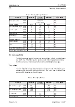
Table 10. RF Characteristics, Transmitter
Item
GSM
PCN
TX frequency range
890...915 MHz
1710...1785 MHz
Type
Upconversion
Upconversion
Intermediate frequency
116 MHz
200 MHz
Maximum output power
2 W (33 dBm)
1 W (30 dBm)
Gain control range
20 dB
20 dB
Maximum RMS phase error
5 deg.
5 deg.
Modulator Circuit, TX part of CRFRT
The modulator is a quadrature modulator contained in Tx–section of
CRFRT IC. The I– and Q– inputs generated by RFI interface are
DC–coupled and fed via buffers to the modulator. The local signal is
divided by two to get accurate 90 degrees phase shifted signals to the I/Q
mixers. After mixing the signals are combined and amplified with
temperature compensated controlled gain amplifier (TCGA). Gain is
controlled with power control signal (TXC). The output of the TCGA is
amplified and the maximum output level is –10 dBm, typically.
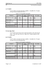
Table 11. CRFRT TX–part specifications
Parameter
Minimum
Typical /
Nominal
Maximum
Unit / Notes
Supply voltage
4.27
4.5
4.73
V
Supply current
36
45
mA
Transmit Frequency Input
Minimum
Typical /
Nominal
Maximum
Unit / Notes
LO input frequency
170
400
MHz
LO input level
0.2
Vpp
LO input resistance
70
100
130
ohm
LO input capacitance
4
pF
Modulator Inputs (I/Q)
Minimum
Typical /
Nominal
Maximum
Unit / Notes
Input bias current (balanced)
100
nA
Input common mode voltage
2.0
2.2
2.4
V
Input level (balanced)
1.1
Vpp
Input frequency range
0
300
kHz
Input resistance (balanced)
200
kohms
Input capacitance (balanced)
4
pF
Output frequency
85
200
MHz
Содержание 9000i
Страница 7: ...After Sales Technical Documentation RAE RAK 1N Series Original 08 96 Chapter 1 Overview ...
Страница 67: ...After Sales Technical Documentation RAE RAK 1N Series Amendment 1 04 97 Chapter 3 Transceiver GE8 GE9 RF Block ...
Страница 93: ...After Sales Technical Documentation RAE RAK 1N Series Chapter 4 Transceiver GE8 GE9 UIF Module ...
Страница 106: ...After Sales Technical Documentation RAE RAK 1N UIF Page 4 14 Amendment 1 04 97 This page intentionally left blank ...
Страница 107: ...After Sales Technical Documentation RAE RAK 1N Series Original 08 96 Chapter 5 Transceiver GE8 GE9 SIM Flex Module ...
Страница 112: ...After Sales Technical Documentation RAE RAK 1N SIM Flex Page 5 6 Original 08 96 This page intentionally left blank ...
Страница 113: ...After Sales Technical Documentation RAE RAK 1N Series Original 08 96 Chapter 6 PDA Hardware Module GP1 ...
Страница 116: ...After Sales Technical Documentation RAE RAK 1N PDA Hardware Page 6 4 Original 08 96 This page intentionally left blank ...
Страница 158: ...After Sales Technical Documentation RAE RAK 1N PDA Hardware Page 6 46 Original 08 96 This page intentionally left blank ...
Страница 159: ...After Sales Technical Documentation RAE RAK 1N Series Amendment 1 04 97 Chapter 7 Service Software ...
Страница 243: ...After Sales Technical Documentation RAE RAK 1N Series Original 05 97 Chapter 8 Faultfinding Disassembly ...
Страница 287: ...After Sales Technical Documentation RAE RAK 1N Series Original 08 96 Chapter 9 Service Tools ...
Страница 301: ...After Sales Technical Documentation RAE 1N Series Original 04 97 Chapter 10 Schematics ...
Страница 303: ...RAE 1N Original 08 96 10 11 Page 1 Figure 1 Component Layout Bottom ...
Страница 304: ...RAE 1N Original 08 96 10 12 Page Figure 2 Component Layout Top ...
Страница 305: ...RAE 1N Original 08 96 10 13 Page Figure 3 Baseband Circuit Diagram PWRU ...
Страница 306: ...RAE 1N Original 08 96 10 14 Page Figure 4 Baseband Circuit Diagram MCM1 ...
Страница 307: ...RAE 1N Original 08 96 10 15 Page Figure 5 Baseband Circuit Diagram MCM2 ...
Страница 308: ...RAE 1N Original 08 96 10 16 Page Figure 6 RF TX Circuit Diagram ...
Страница 309: ...RAE 1N Original 08 96 10 17 Page Figure 7 RF RX Circuit Diagram ...
Страница 310: ...RAK 1N 10 20 Page Amendment 1 04 97 Figure 18 PCN Component Layout Bottom ...
Страница 311: ...RAK 1N 10 21 Page Amendment 1 04 97 Figure 19 PCN Component Layout Top ...
Страница 312: ...RAK 1N 10 22 Page Amendment 1 04 97 Figure 20 PCN RF TX ...
Страница 313: ...RAK 1N 10 23 Page Amendment 1 04 97 Figure 21 PCN RF RX ...
Страница 314: ...RAK 1N 10 24 Page Amendment 1 04 97 Figure 22 UIF Schematic PCN ...
Страница 315: ...RAK 1N 10 25 Page Amendment 1 04 97 Figure 23 UIF Component Layout PCN ...
Страница 316: ...RAE 1N Original 05 97 10 3 Page Figure 1 PDA Block Diagram Edit 82 for layout 13a ...
Страница 317: ...RAE 1N Original 05 97 10 4 Page Figure 2 PDA Power Unit PWRU Edit 108 for layout 13a ...
Страница 318: ...RAE 1N Original 05 97 10 5 Page Figure 3 PDA Serial Interface SIRU Edit 24 for layout 13a ...
Страница 319: ...RAE 1N Original 05 97 10 6 Page Figure 4 PDA MCU and Memory PROCU Edit 121 for layout 13a ...
Страница 320: ...RAE 1N Original 05 97 10 7 Page Figure 5 PDA EMIU Edit 21 for layout 13a ...
Страница 321: ...RAE 1N Original 05 97 10 8 Page Figure 6 Keyboard matrix Edit 24 for layout 13a ...
Страница 322: ...RAE 1N Original 05 97 10 9 Page Figure 7 PDA Memory Edit 28 for layout 13a ...
Страница 323: ...RAE 1N Original 05 97 10 10 Page Figure 8 PDA Component Layout 13a ...
Страница 324: ...RAE 1N Original 08 96 10 18 Page Figure 1 UIF Schematic ...
Страница 325: ...RAE 1N Original 08 96 10 19 Page Figure 2 Component Layout Uif ...
Страница 326: ...After Sales Technical Documentation RAE RAK 1N Series Original 08 96 Accessories ...
Страница 340: ...After Sales Technical Documentation RAE RAK 1N Series Original 08 96 CARK60 Installation Guide ...
Страница 352: ...After Sales Technical Documentation Appendix 2 RAE RAK 1N Amendment 1 04 97 PARTS LISTS ...
Страница 399: ...After Sales Technical Documentation RAE RAK 1N Parts Lists Page 48 Amendment 1 04 97 Mechanical Assy Parts RAE 1N ...
Страница 401: ...After Sales Technical Documentation RAE RAK 1N Parts Lists Page 50 Amendment 1 04 97 This page intentionally left blank ...
Страница 402: ...After Sales Technical Documentation Appendix 1 RAE RAK 1N Original 08 96 QUICK GUIDE ...
Страница 434: ......


