Use and maintenance manual model “UNICA 10 V/C” - WOOD
ENGLISH
15
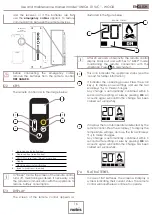
When replacing the batteries, it will not be
necessary to pair the remote control again.
When the question "FIRST INSTALLATION?" will be
displayed, select
NO
and press
OK
.
If the automatic connection is hindered by
any interference, it is possible to repeat the
connection procedure by forcing a fixed channel
(
CH1
or
CH2
) using the directional keys ↑ ↓, or else
by inserting the batteries, answering
YES
to the
question “NEW INSTALLATION?”; when the display
will ask you to press the button on the electronic
card, before pressing it, use the directional buttons
on the remote control to choose one of the two
fixed channels instead of
AUTO
. If interferences
are still disrupting the connection, find out which
device is causing it and have it checked by its
manufacturer's technical support.
AUTO
CH 1
↓
↓
CH 2
6.2 EXTERNAL THERMOSTAT
If you want to manage the appliance from a
different room (in that specific room, the remote
handheld device cannot communicate), you can
connect an external thermostat to the product, to
allow modulation of combustion or, by activating
a particular function, allow switch on or off of
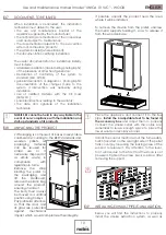
the product. As in the figure below, connect the
terminals of the thermostat to the terminal board
on the back of the product (near the emergency
panel).
TERMINAL
EXTERNAL THERMOSTAT
The external thermostat MUST operate with "clean
contact" or "dry contact" in normally “closed
mode”, otherwise the electronic control unit will
be damaged. Once connected, the recognition
function must be enabled to allow the control unit
to detect the presence of the external thermostat,
from the USER SETTINGS menu (see the paragraph
“ENABLE EXTERNAL THERMOSTAT”).
Enabling the external thermostat will deactivate
the temperature management functions on the
remote control. In such csae, the remote control
will display TON if room temperature has not been
reached yet, otherwise the writing TOFF will be
displayed.
6.3 LOADING LOGS
Firewood must be loaded by inserting the logs
into the fireplace following the instructions given
in Chapter 9.
7
REMOTE CONTROL
Before switching on the appliance, you are
advised to read the following chapter carefully
relating to use of the receiver and the remote
control, as well as their related functions.
INFORMATIVE NOTE:
• frequency bands and transmitted power used
by the equipment as reported in the technical
documents: 868.3MHz - 869.85MHz
• frequency bands and respective power limits
transmitted applicable to the device (frequencies
and standardized powers): 6dBm ERP
7.1 RECEIVER
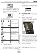
The appliance is equipped with an emergency
remote board, placed at the back of it, which
allows basic management of the functions in the
event the remote control is faulty or not working
properly.
1
3
2
4 5
6 7
8
9
10
1
Serial connection (use by authorised staff ONLY)
2
USB connection (use by authorised staff ONLY)
3
Emergency cable connection
4
GREEN LED - appliance working status
5
YELLOW LED - remote communication in progress
6
RED LED - alarm on
7
BLUE LED - System updating in progress
8
Appliance switch on/off button
9
Receiver handheld device remote combination
button
10
Manual upgrade button
(use by authorised staff ONLY)
In the event of malfunctioning of the remote
communication between the remote control
Содержание UNICA 10 V/C
Страница 1: ...EN Installation use and maintenance manual WOOD UNICA 10 V C...
Страница 25: ...Use and maintenance manual model UNICA 10 V C WOOD ENGLISH 25 MAINTENANCE DATE MAINTENANCE TASK PERFORMED...
Страница 26: ...Use and maintenance manual model UNICA 10 V C WOOD ENGLISH 26 MAINTENANCE DATE MAINTENANCE TASK PERFORMED...
Страница 27: ...Use and maintenance manual model UNICA 10 V C WOOD ENGLISH 27 MAINTENANCE DATE MAINTENANCE TASK PERFORMED...

