background image

Shredders

72

10. - Maintenance and storage

TBE GBseries 102

JN070AGB B

10.5 Storage

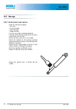
10.5.1 At the end of each season

- Clean the machine thoroughly:

• The rotor.
• The inner panels.
• Rotor housings.
• Roller housings.

- Touch up any areas of damaged paintwork.
- Lubricate all mechanical components correctly to

protect them from corrosion.

- Put the machine under cover in a dry place.
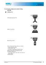
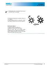
- Check the condition of the securing elements

regularly and also the torque of the knife-fixing bolt.
Replace if necessary.

- Check that the original safety decals are in their

original location, undamaged and legible.

- Drain bevel gearbox and fill with new oil.
- Slacken V-belts and check their condition.

- Grease the cylinder rods in contact with the

outside.

Содержание TBE GB 102 Series

Страница 1: ...Original instructions JN070AGB B Read carefully before starting the machine OPERATOR S MANUAL Shredders TBE GBseries 102 JN070AGB B English 06 2015...

Страница 2: ......

Страница 3: ...S MANUAL AVAILABLE FOR REFERENCE Pass it on to the next owner if you re sell the machine Your dealer can offer a complete line of genuine NOBILI service parts These parts are manufactured and carefull...

Страница 4: ...fore using the machine 10 4 2 5 Precautions when driving 11 4 2 6 Precautions when driving on public roads 12 4 2 7 Maximum speed 16 4 2 8 Precautions when coupling 16 4 2 9 Hydraulic circuit 17 4 2 1...

Страница 5: ...it 40 6 1 7 Rubber flaps 41 6 1 8 Uncoupling the machine 42 6 1 9 Handling 43 7 Instructions for transport 44 7 1 Putting the machine into transport position 44 7 2 Conformity with the road regulation...

Страница 6: ...ease 60 10 3 3 Oil change 61 10 4 Maintenance 62 10 4 1 Checking the oil levels 62 10 4 2 Check cutting tools and their fixing elements 63 10 4 3 Belt tension 68 10 5 Storage 72 10 5 1 At the end of e...

Страница 7: ...Shredders 3 Identification of the machine 5 TBE GBseries 102 JN070AGB B 3 Identification of the machine 3 1 Front view 3 2 Rear view...

Страница 8: ...achine TBE GBseries 102 JN070AGB B 3 3 Model identification plate Please write below the type and serial number of the machine This information is to be given to your NOBILI dealer for all parts order...

Страница 9: ...on of the machine 7 TBE GBseries 102 JN070AGB B 3 4 Optional equipment Tick box corresponding to the equipment fitted on your machine Cable controls Double wide angle constant velocity PTO shaft Later...

Страница 10: ...ol indicates a potentially hazardous situation that if not avoided could result in serious bodily injury This symbol is used to identify special instructions or procedures which if not followed strict...

Страница 11: ...and accessories as recommended by the manufacturer The manufacturer is not held liable for any damage resulting from machine applications other than those specified by the manufacturer Any use other...

Страница 12: ...ot wear loose clothing which could become caught up in moving parts Wear the appropriate protective clothing for the work in hand gloves shoes goggles helmet ear defenders etc Ensure that all operatin...

Страница 13: ...rator exercises caution in every given situation Groundspeed must be adapted to ground conditions as well as to roads and paths Always avoid abrupt changes of direction Be particularly cautious when t...

Страница 14: ...s for special transportation of oversize equipment Transport position Before transporting the machine on public roads place the machine into its transport position according to the instructions in thi...

Страница 15: ...0 of the tractor unladen weight For machines with hoppers or tanks If the total unit weight exceeds the tractor Gross Combined Weight Rating in accordance with the countrie s legislation empty the hop...

Страница 16: ...ition To do If the front axle load t1 is below 20 of the tractor tare T add ballast weights M1 to exceed the minimum load on the front axle Example T 7500 kg 16535 lb The front axle load must be of mi...

Страница 17: ...ple t 10000 kg 24250 lb PTAC 13000 kg t PTAC Go to the next stage kg kg t _____kg To measure Load on rear axle t2 Tractor machine transport position Ballast weights Checking Check in the tractor s ope...

Страница 18: ...ching the machine make sure that it cannot accidentally start moving chock the wheels and that the parking stand is in the right position The machine must only be attached to the hitch points provided...

Страница 19: ...raulic hoses In case of normal wear replace the hydraulic hoses every 5 years Damaged or worn hoses must immediately be replaced When replacing the hydraulic hoses only use hoses with the specificatio...

Страница 20: ...even a lethal accident Do not wear loose clothing that could be caught in the rotating PTO shaft Before attaching or removing a PTO shaft or before doing any work on the machine disengage the PTO driv...

Страница 21: ...end of the splined shaft and the added adaptor device as outlined in the table When uncoupling the machine rest the PTO shaft on the support specially provided and replace protective shield on the PTO...

Страница 22: ...Safety decals Safety warning decals are placed in pictorial form on various parts of the machine They are there to warn you of potential dangers and to tell you how to avoid accidents Always keep the...

Страница 23: ...on the electric circuit or before any electric welding is carried out on the attached machine disconnect the machine from the tractor electrical circuit Also disconnect alternator and battery terminal...

Страница 24: ...ds on their exterior Increase the cutting height to avoid contact with stones or rocks Never start the shredder when there are people nearby Even when the machine is used in accordance with its purpos...

Страница 25: ...s Before engaging the PTO drive lower the machine on the ground Make sure all the guards are in place Keep all persons and animals away from the danger zone Stay a safe distance from the machine when...

Страница 26: ...ds dumps or inert material dumps To eliminate cloggings take the following safety measures Switch off the engine Lift the machine using the tractor s lift linkage Put on gloves and protective glasses...

Страница 27: ...dders 4 Safety 25 TBE GBseries 102 JN070AGB B 4 3 Location and description of safety decals on the machine 4 3 1 Location of safety decals 133047 136009 12 540 9 1 2 3 4 5 4 6 7 8 10 10 10 11 13 14 15...

Страница 28: ...g on the machine 2 Before leaving the tractor or before adjusting maintaining or repairing the machine disengage the PTO drive turn off the engine remove ignition key and wait until all moving parts h...

Страница 29: ...e the engine is running the PTO drive engaged and the moving parts have not come to a complete stop Moving elements 5 Do not open or remove guards when the engine is running 133047 Support wheels 6 At...

Страница 30: ...erate in an area where there is a crushing risk before all moving parts have come to a complete stop Danger of falling 8 Do not ride on the machine Power requirement 9 Machine preset for a 540 drive 5...

Страница 31: ...jets under pressure Use of guards 12 Wear the appropriate protective clothing for the work in hand gloves shoes goggles helmet ear defenders etc 136009 Risk of injuries 13 Before adjusting maintainin...

Страница 32: ...ed 14 Do not stay between the machine and the tractor Risk of entanglement 15 Stay clear of rotating drive line Projections 16 Stones and other debris projected by the moving parts can travel a long d...

Страница 33: ...y equipment is mounted in the factory or by your NOBILI dealer according to current safety regulations Always keep to the legal speed limit for driving a tractor machine assembly on public roads The r...

Страница 34: ...achine specifications 5 1 Description and glossary 0 1 Three point hitch coupler 2 Shredding unit 3 Offset cylinder 4 Shredding unit pivoting cylinder 5 Locking cock open 6 Antishock unit 7 Side guard...

Страница 35: ...ower Side gearbox 96 kW 130 hp 110 kW 150 hp 125 kW 170 h p Free wheel Inside central gearbox Power takeoff rotation frequency 540 min 1 540 min 1 540 min 1 Quantity type of belts 4 x QP3 1600 Rotor s...

Страница 36: ...d Common safety recommendations Weighted equivalent continuous acoustic pressure level at the driver s seat closed cabin L A eq according to standard UNI EN ISO 11201 TBE192 GB 85 0 dB A TBE222 GB 85...

Страница 37: ...n of coupling elements A PTO shaft 1 3 8 6 splines A 3 point hitch 2 hydraulic hoses that control the lateral offset cylinder 1 hydraulic hose that controls the cutting head cylinder 6 1 2 Preparing t...

Страница 38: ...machine Check that the hitch frame is locked with lock pin 1 Lower the tractor three point linkage Attach the lower links to the hitch pins Adjust height from ground at 420 mm Secure each hitch pin w...

Страница 39: ...ck it 3 Adjust stabilizers of lower links to prevent side to side movements of the machine 3 3 3 3 Prevent lift arm height modification in order not to alter the settings Offset cylinder Connect hydra...

Страница 40: ...ength of the PTO shaft When the PTO shaft is in its maximum overlap position retracted tubes should not butt against the yokes As a safety measure a clearance L of at least 25 mm 1 must be maintained...

Страница 41: ...PTO shaft at an angle X exceeding 30 X X To avoid serious accidents the PTO drive shaft guards must be properly in place and fixed with the chains provided On machine side attach PTO shaft guard chain...

Страница 42: ...ivot rearwards and to regain automatically its initial position after having cleared the obstacle The safety breakback is adjusted by means of nuts 1 The measure X is factory set at 80 mm 3 3 This adj...

Страница 43: ...The hood is fitted with rubber segments to prevent the ejection of stones or other objects Immediately replace any worn or damaged segments Remove the mounting bolts 1 Remove mounting bar 2 Replace s...

Страница 44: ...se the cutting head orientation cylinder cock 1 1 1 Lower and lock parking stands 2 Lower the tractor three point linkage to rest the machine on the ground Disconnect the PTO shaft from the tractor Se...

Страница 45: ...r complying with safety standards in force for this type of equipment and with capacities that exceed the total weight of the unit as listed in this manual TBE192 GB 925Kg 2040 lb TBE222 GB 970Kg 2140...

Страница 46: ...lacing the machine into transport position Wait until the rotating parts have come to a complete stop Check that nobody is within the machine pivoting area If there is someone make sure the person mov...

Страница 47: ...nformity with the road regulations Check that reflectors are clean Close the cutting head orientation cylinder cock 1 1 1 Never engage the tractor PTO drive when the machine is in transport position B...

Страница 48: ...structions for work 8 1 Putting the machine into work position 8 1 1 Cylinders locking Check that nobody is within the machine operating area The cutting head orientation one way cylinder lets the mac...

Страница 49: ...Bseries 102 JN070AGB B 8 1 2 Hitch frame unlocking The pivot pin between the hitch frame and the shredding unit arms enables the machine s adaptation to ground contours during work Unlock and remove p...

Страница 50: ...ne can be used in 4 positions TBE 192 GB TBE 222 GB TBE 242 GB A 764 mm 2 6 764 mm 2 6 827 mm 2 9 B 2175 mm 7 2 2175 mm 7 2 2175 mm 7 2 C 1792 mm 5 11 2144 mm 7 2295 mm 7 6 D 2806 mm 9 2 3158 mm 10 4...

Страница 51: ...unit The cutting tools must never touch the ground Slightly lift the machine from the ground Loosen bolts 1 Remove bolts 2 Position roller in holes corresponding to the required adjustment Reinstall b...

Страница 52: ...Check that the 2 skids are set identically Slightly lift the machine from the ground Loosen bolts 1 Remove screw 2 Position work skid in hole corresponding to the required setting Reinstall and tighte...

Страница 53: ...Adjust lift linkage height to obtain a perfectly horizontal position For an adapted setting adjust lift linkage height until lower edge of offset arm lower part is parallel to the ground Avoid modify...

Страница 54: ...Pay particular attention if working on very uneven grounds protections may momentarily be ineffective and allow ejection of stones or foreign objects over a wide radius If using a tractor with a cab...

Страница 55: ...tractor three point linkage to rest the machine on the ground 8 3 1 Drive speed Groundspeed must be adapted to the encountered working conditions If the machine starts vibrating oddly during work imm...

Страница 56: ...c valve in detented position to obtain a constant flow Operate cable controls to monitor the required function The cable controls enable using only one tractor single acting valve with free return The...

Страница 57: ...bles to work at great angles a long time The use of a wide angle pto shaft is recommended for work in vertical configuration 9 2 1 Lubrication Clean grease nipples before greasing Lubricate with EP 2...

Страница 58: ...road regulations the machine must be fitted with specific signalling panels when driving on public roads The rear safety device comprises The rear safety device comprises 1 self adhesive panel 1 1 1...

Страница 59: ...hart Before adjusting maintaining or repairing the machine turn off ignition key and wait until all moving parts have come to a complete stop Every 4 hours Every 8 hours Every 20 hours Every 50 hours...

Страница 60: ...e and storage TBE GBseries 102 JN070AGB B The PTO shaft guiding bushes Pivot points Rotor bearings Roller removable bottoms Every 4 hours Every 8 hours Every 20 hours Every 50 hours Every 250 hours or...

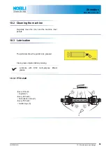
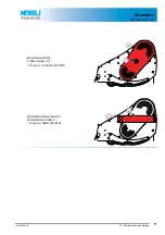
Страница 61: ...ean the rotor and the machine inner panels 10 3 Lubrication Clean grease nipples before greasing 10 3 1 PTO shaft The pictorials show the points to be greased Lubricate with EP 2 multi purpose lithium...

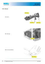
Страница 62: ...Shredders 60 10 Maintenance and storage TBE GBseries 102 JN070AGB B 10 3 2 Grease Pivot points Rotor bearings Roller removable bottoms...

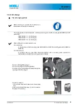
Страница 63: ...lling it is recommended to use For normal use A mineral base oil with viscosity grade SAE 80W90 or 85W140 and API grade GL5 80W90 or 85W140 For intensive use A synthetic base oil type PAO Poly Alpha O...

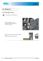
Страница 64: ...B 10 4 Maintenance 10 4 1 Checking the oil levels Place the machine on level ground Check central gearbox oil level Place the machine on level ground Remove level plug 1 1 1 The oil level must reach l...

Страница 65: ...cutting tools before each use in order to ensure shredding quality ensure safety in use avoid risk of damaging the fixing elements Replace cutting tools in the following cases Damaged cutting tools Ve...

Страница 66: ...must exceed 90 mm 3 54 Ovalisation of the mounting hole L2 must not exceed 22 mm 0 87 L2 L1 The cutting tool length L1 must exceed 90 mm 3 54 Ovalisation of the mounting hole L2 must not exceed 22 mm...

Страница 67: ...f ft Check the securing elements After hitting an obstacle When knives are replaced At the start of each season The fixing bolts should be changed in the following cases Replace the shackles in the fo...

Страница 68: ...in the existing balance Check that there is still 1 to 2 mm 0 04 0 08 play between the pair of knives and the supports Total replacement Immediately replace worn or damaged parts with original manufac...

Страница 69: ...crease speed progressively up to a steady speed of 540 min 1 When mounted correctly the rotor must rotate without causing the machine to vibrate Put the lighter pairs in the center of the rotor and th...

Страница 70: ...ries 102 JN070AGB B 10 4 3 Belt tension Checking the tension Check belt tension After the first 3 hours of use Every 8 hours Through the belt guard slot Apply a force of 35 N 1 6 lbf on the belt the b...

Страница 71: ...Shredders 10 Maintenance and storage 69 TBE GBseries 102 JN070AGB B Adjusting the tension Remove 4 bolts 1 Remove reinforcement 2 2 1 Loosen screw 1 Remove guard 2 2 1...

Страница 72: ...belts individually When a belt is damaged always replace the whole set Loosen the 4 screws 4 that hold the central gearbox Loosen counternuts 5 Rotate the 2 adjustment screws 6 equally until reaching...

Страница 73: ...ers 10 Maintenance and storage 71 TBE GBseries 102 JN070AGB B Reinstall guard 2 Tighten screw 1 1 Torque 13 5 daNm 99 lbf ft 2 1 Reinstall reinforcement 2 Reinstall the 4 bolts 1 Torque 9 daNm 65 lbf...

Страница 74: ...mechanical components correctly to protect them from corrosion Put the machine under cover in a dry place Check the condition of the securing elements regularly and also the torque of the knife fixing...

Страница 75: ...firmly secured in place Make sure all the guards are in place Wipe off grease on cylinder rods 10 6 Machine recycling In case of recycling the machine will have to be recycled in conformity with the l...

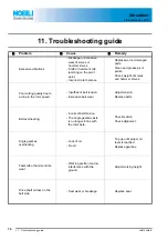
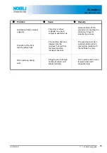
Страница 76: ...knives Poor cutting quality due to a drop in the rotor speed Insufficient belt tension Excessive belt wear Adjust tension Replace belts Belt overheating incorrect belt tension The angle gearbox axle...

Страница 77: ...vel or steering the wheels Distortion of the front pivoting safety flaps The machine has been lowered onto the residues to shred from the raised position transport position The machine must be in work...

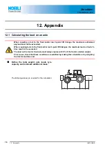
Страница 78: ...mum authorized payload must not be exceeded When coupling tools to the front and or rear 3 point lift linkages the maximum load on tractor s tires must not be exceeded The load on the tractor front ax...

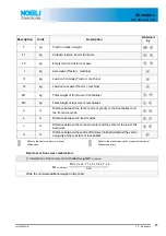
Страница 79: ...ravity or the front ballast and the front axle centre b m Distance between the tractor axles c m Distance between the rear axle center and the center of the lower link ball joints d m Distance between...

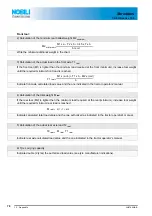
Страница 80: ...the one indicated in the tractor operators manual T1 real M1 x a b T1 x b M2 x c d b 4 Calculation of the total weight M real If the rear tool M2 is lighter than the minimum load required at the rear...

Страница 81: ...or s manual Double value of the authorized capacity per tyre 2 tyres Minimum front rear ballasting kg Total weight kg kg Load on front axle kg kg kg Load on rear axle kg kg kg The minimum ballasting m...

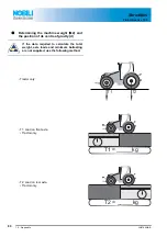
Страница 82: ...M2 and the position of its centre of gravity d If the data required to calculate the total weight axle loads and minimum ballasting are not supplied use the following method Tractor only T1 T2 T1 Load...

Страница 83: ...Shredders 12 Appendix 81 TBE GBseries 102 JN070AGB B T Axle loads Tractor only T _____kg...

Страница 84: ...e tractor Gross Combined Weight Rating in accordance with the countrie s legislation empty the hopper to travel on public roads In any case we recommend to travel on public roads with empty hoppers an...

Страница 85: ...Shredders 12 Appendix 83 TBE GBseries 102 JN070AGB B Calculating the rear tool weight M2 M2 t T Calculating the distance d d b x T1 t1 M2 c t Axle loads Tractor machine Hopper empty t _____kg...

Страница 86: ...84 13 Limited Warranty TBE GBseries 102 Shredders 13 Limited Warranty...

Страница 87: ...acheteur conforme alla Direttiva Europea 2006 42 CE Per l adeguamento della macchina sono state consultate le seguenti Norme Armonizzate EN ISO 4254 12 2012 EN 13524 2014 EN ISO 4254 6 2010 EN ISO 425...

Страница 88: ......

Отзывы: