Chassis System
15
Service Manual – Scrubtec 337.2 / Vantage 14
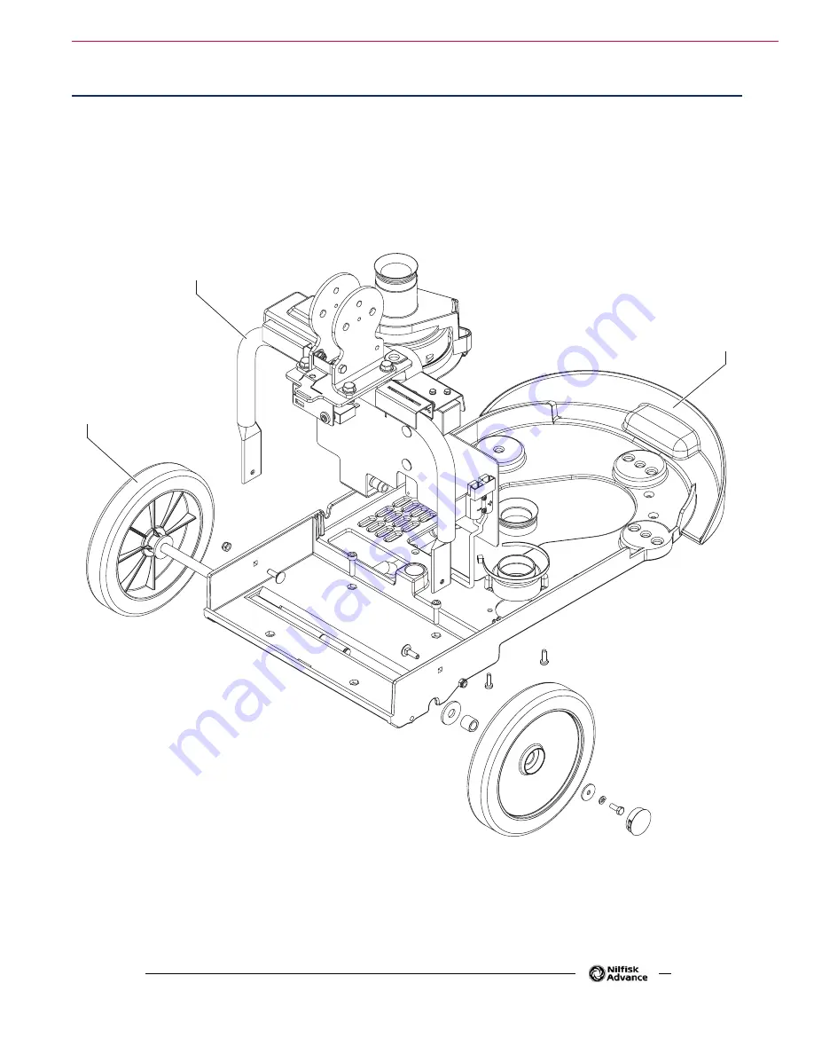
Frame (main parts)
1 Frame
2 Handlebar holder
3
Wheels on fixed axle
1
2
P100775
Страница 1: ...Scrubtec 337 2 Vantage 14 2013 05 Form No 9099961000 Service Manual Nilfisk ALTO Scubtec 337 2 9087343020 Clarke Vantage 14 9087345020 English...
Страница 2: ...and Diagnostic Equipment 11 Technical Data 12 Dimensions 13 Maintenance 14 Scheduled Maintenance Table 14 Chassis System 15 Frame main parts 15 Control System 16 Functional Description 16 Component L...
Страница 3: ...oval and Installation 45 Specifications 48 Solution System 49 Functional Description 49 Wiring Diagram 49 Component Locations 50 Troubleshooting 52 Removal and Installation 53 Specifications 54 Squeeg...
Страница 4: ...ose and Field of Application The Service Manual is a technical resource intended to help service technicians when carrying out mainte nance and repairs on the SC351 to guarantee the best cleaning perf...
Страница 5: ...fying the machine model and serial number Apply Retailer label here Serial Number Label The machine serial number and model name are marked on the plate see the example to the side Product code and y...
Страница 6: ...Instructions Specific warnings and cautions to inform about potential damages to people and machine are shown below Warning Make sure to follow the safety precautions to avoid situations that may lea...
Страница 7: ...efore using the machine close all doors and or covers as shown in the User Manual This machine is not intended for use by persons including children with reduced physical sensory or mental capabilitie...
Страница 8: ...nd seriously damage the machine Use brushes and pads supplied with the machine or those specified in the User Manual Using other brushes or pads could reduce safety In case of machine malfunctions ens...
Страница 9: ...tem motor Rear wheels on fixed axle Brush deck gearmotor Brush deck wheels Squeegee vacuum hose Transparent cover with vacuum grid Vacuum grid with automatic shut off float Brush pad holder deck Deck...
Страница 10: ...on Solution flow activation Machine switching off 0 Handlebar inclination adjusting lever Brush levers Solution flow switch Machine start up enabling push button Program selection knob rotary switch S...
Страница 11: ...Reader and if possible Internet connection Digital Volt Meter DVM Amp clamp with possibility of making DC measurements Hydrometer Battery charge tester to check 12 V batteries Static control wrist str...
Страница 12: ...ound pressure level ISO 3744 ISO 4871 EN 60335 2 72 LwA 84 dB A Vibration level at the operator s arms ISO 5349 1 EN 60335 2 72 98 4 in s2 2 5 m s2 Maximum gradient when working 2 IP protection class...
Страница 13: ...General Information 13 Service Manual Scrubtec 337 2 Vantage 14 Dimensions 28 6 in 726 mm 18 7 in 475 mm 17 in 432 mm 17 in 432 mm P100774A...
Страница 14: ...e The intervals shown may vary according to particu lar working conditions which are to be defined by the person in charge of the maintenance For instructions on maintenance procedures see the followi...
Страница 15: ...Chassis System 15 Service Manual Scrubtec 337 2 Vantage 14 Chassis System Frame main parts 1 Frame 2 Handlebar holder 3 Wheels on fixed axle 1 2 3 P100775...
Страница 16: ...uffi cient and the battery charger is not connected to the electrical mains The LED electronic board EB1 is equipped with 3 LEDs which indicate the battery charge level both during operation and while...
Страница 17: ...levers Machine start up enabling push button SW2 Solution flow push button SW3 Wiring harness Handlebar inclination adjusting lever Handlebar with control panel Solution flow switch SW3 Machine start...
Страница 18: ...ection knob to 0 3 Disconnect the battery connector 4 On the lower side of the handlebar with the control panel unscrew the screws A 5 Lower the upper side B of the handlebar with the control panel 6...
Страница 19: ...knob I as shown below Disconnect the connectors J On the outer side turn the knob I on the position K vacuum system activation Loosen the threaded dowel inside the housing L then remove the knob I fr...
Страница 20: ...control panel unscrew the screws A 5 Move the upper side B of the handlebar with the control panel 6 Remove the screws C and move the lower side D of the handlebar from the frame E 7 Disconnect the c...
Страница 21: ...oard connector EB1 JA 4 way vertical Tyco Modu II type 2 3 4 1 PIN Description Electronic board in out V ref I max 1 Common cathode LED power supply in 0 V 1 A 2 RED anode LED power supply in 0 7 V 1...
Страница 22: ...assed when the solution flow switch SW3 is turned to 1 maximum flow The battery charger CH supplies negative power to all the control relays only when the battery charge is suf ficient and the battery...
Страница 23: ...1 Vacuum system motor fuse F2 Function selector fuse F3 Brush motor relay K1 Solenoid valve timer relay KT1 Vacuum system motor relay K2 12V Battery BAT Battery charger CH Function selector fuse F3 Va...
Страница 24: ...ging Note Charge the batteries when the yellow or red LED turns on or at the end of each working cycle Keeping the batteries charged make their life last longer Caution When the battery is discharged...
Страница 25: ...N SW1 DP1 DP2 RED YELLOW GREEN LED LED LED P100783 SW1 LED CODES CHARGING CURVES DP1 DP2 BATTERY CHARGING LEDS on the control panel ON ON 2 flashes of the GREEN LED Charging algorithm for generic Gel...
Страница 26: ...n knob is turned to 0 and disconnect the battery connector 3 Open the cover and check one of the following fuses for deactivation or integrity A brush motor fuse circuit breaker F1 35 A B vacuum syste...
Страница 27: ...s connections are not efficient Charge the batteries or clean repair the connections The 12V batteries BAT are broken Check the battery no load voltage The battery charger CH is broken Replace The fun...
Страница 28: ...RD EB1 BRUSH MOTOR FUSE F1 VACUUM SYSTEM MOTOR FUSE F2 FUNCTION SELECTOR FUSE F3 BRUSH MOTOR RELAY K1 BRUSH MOTOR RELAY K1 VACUUM SYSTEM MOTOR RELAY K2 VACUUM SYSTEM MOTOR RELAY K2 SOLENOID VALVE TIME...
Страница 29: ...ilfisk Alto SCRUBTEC 337 2 Clarke VANTAGE 14 Total absorbed power 42 A 0 5 kW Battery compartment size 17 8x6 9x9 4 in 350x175x240 mm Battery voltage 12 V Standard batteries 12V 55AhC20 AGM spiralcell...
Страница 30: ...um system motor M2 is supplied by the vacuum system motor relay K2 which is driven by the program selection knob rotary switch SW1 when it is turned to 1 or 3 The circuit is protected by the vacuum sy...
Страница 31: ...tec 337 2 Vantage 14 Component Locations Recovery tank Vacuum system tank connection gasket Squeegee vacuum hose Vacuum system motor M2 Recovery tank Squeegee vacuum hose Vacuum system tank connection...
Страница 32: ...ations Continues Transparent cover Vacuum grid with automatic shut off float Cover gasket Vacuum system motor fuse F2 Vacuum system relay K2 Cover gasket Transparent cover Vacuum grid with automatic s...
Страница 33: ...ble the grid B and remove the float E than clean with care and reinstall 6 Check the recovery tank cover gasket F for integrity Note The gasket F creates vacuum in the tank that is necessary for vacuu...
Страница 34: ...n a level floor 2 Check that the function selection knob is turned to 0 and disconnect the battery connector 3 Open the cover A and check the vacuum system motor gasket L for integrity 4 If necessary...
Страница 35: ...dirty Clean The transparent cover is not properly positioned Adjust The tank cover gasket is not sealing Clean replace The vacuum system motor filter is dirty Clean The vacuum gaskets are damaged or...
Страница 36: ...k that the motor amperage is between 15 and 18 A at 12 V 5 Turn the knob to 0 6 Remove the amp clamp B 7 If the amperage is higher than specified disassemble the vacuum system motor see the procedure...
Страница 37: ...crews D recover the washers and nuts 6 Remove the motor cover E and recover the gasket F 7 Remove the motor B and the acoustic insulation pipe G 8 Check the gasket F and the gasket H for damage If nec...
Страница 38: ...Scrubtec 337 2 Vantage 14 Specifications Description Nilfisk Alto SCRUBTEC 337 2 Clarke VANTAGE 14 Recovery tank capacity 2 9 USgal 11 litres Vacuum system motor power 0 27 hp 200 W Vacuuming with clo...
Страница 39: ...uit is protected by the brush motor fuse F1 The system once activated uses the solution coming form the solution system to wash the floor To work properly the brush motor needs the following Program s...
Страница 40: ...hub Machine forward speed adjusting handwheel Machine straight forward movement adjusting handwheel Deck rotation end of stroke system Machine straight forward movement adjusting handwheel Brush moto...
Страница 41: ...Scub Sytem Disc 41 Service Manual Scrubtec 337 2 Vantage 14 Component Locations Continues Brush motor fuse F1 Brush motor relay K1 Brush motor fuse F1 Brush motor relay K1 P100781...
Страница 42: ...nd the choice of using the brush or the pad If necessary perform the adjustments as shown 1 Remove the recovery and the detergent tanks 2 Adjust the machine speed with the handwheel A Turn the handwhe...
Страница 43: ...the motor Trouble Possible Causes Remedy The brush does not clean properly The brush is excessively worn Replace The brush does not turn The motor is faulty Check the motor amperage replace There are...
Страница 44: ...tor 6 Turn on the brush by pressing the push button 39 together with the levers 40 then check that the motor amperage C is 6 to 8 A at 12 V 7 Turn off the brush by releasing the levers 40 8 Turn the k...
Страница 45: ...ssion pin key C 6 Remove the 4 screws D the deck flange E and disassemble the brush deck F 7 Check the rubber pads G for integrity and replace them if excessively worn Note The rubber pads G allow the...
Страница 46: ...in the figure Assembly 12 Assemble the components in the reverse order of disassembly and note the following Couple the tooth M of the end of stroke spacer tab N and the deck flange as shown in the f...
Страница 47: ...the battery connector is disconnected 3 Disconnect the gearmotor connector A and the detergent hose B 4 Lift the machine and remove the brush 5 Disassemble the brush deck as shown by the previous proc...
Страница 48: ...14 Specifications Description Nilfisk Alto SCRUBTEC 337 2 Clarke VANTAGE 14 Brush pad diameter 14 5 in 370 mm Brush pad pressure on the floor 46 lb 21 Kg Brush pad pressure with full tank 66 lb 30 Kg...
Страница 49: ...ch SW1 when it is turned to 1 or 2 and the machine start up enabling push button SW2 When the solution flow switch SW3 is open the solenoid valve EV is driven by solenoid valve timer KT1 2 sec ON 2 se...
Страница 50: ...Service Manual Scrubtec 337 2 Vantage 14 Component Locations Solution tank Filler plug Detergent valve Solenoid valve EV Detergent hose Filler plug Solution tank Detergent hose Detergent valve Solenoi...
Страница 51: ...Solution System 51 Service Manual Scrubtec 337 2 Vantage 14 Component Locations Continues Solenoid valve timer relay KT1 Solenoid valve timer relay KT1 P200067...
Страница 52: ...place the solenoid valve or repair the electrical connection There is dust debris in the tank or in the detergent hoses obstructing the solution flow Clean the tank hoses The function selector fuse F3...
Страница 53: ...sconnected 3 Remove the cover and the solution and recovery water tanks 4 Remove the solenoid valve power supply connector A 5 Disconnect the hoses B and C under the machine 6 Remove the screws D and...
Страница 54: ...Vantage 14 Specifications Description Nilfisk Alto SCRUBTEC 337 2 Clarke VANTAGE 14 Solution tank capacity 3 2 USgal 12 litri Min max solution flow One drop 0 066 gpm 0 25 litres min Two drops 0 13 gp...
Страница 55: ...unning the conformation of the squeegee and the brush deck rotation mechanism assist in the alignment and accurate vacuuming of the water from the floor The 2 blades have different hardness Front blad...
Страница 56: ...e System 56 Service Manual Scrubtec 337 2 Vantage 14 Component Locations Squeegee Rear blade Rear elastic strap Front blade Front strap Squeegee Rear elastic strap Rear blade Front blade Front strap P...
Страница 57: ...on knob is turned to 0 and disconnect the battery connector 3 Fully turn the brush pad holder deck counter clockwise 4 Disconnect the vacuum hose A from the squeegee 5 Disengage the squeegee B from th...
Страница 58: ...he worn edge with an integral one If the other edges are worn too replace the blade as shown Remove the fastening strap H by disengag ing it from the fasteners I Replace or overturn the rear blade F t...
Страница 59: ...ystem 59 Service Manual Scrubtec 337 2 Vantage 14 Troubleshooting Trouble Possible Causes Remedy Leaving streaks on floor There is debris under the blade Remove The squeegee blade edges are torn or wo...
Страница 60: ...Manual Scrubtec 337 2 Vantage 14 Wheel System Non Traction Component Locations Rear wheels on fixed axle Castors on brush deck Rear wheels on brush deck Castors on brush deck Rear wheels on brush dec...
Страница 61: ...tion 61 Service Manual Scrubtec 337 2 Vantage 14 Specifications Description Advance SC351 Nilfisk SC351 Nilfisk SC351 full PKG Diameter of wheels on fixed axle 8 4 in 214 mm Wheel pressure on the floo...