


Wheel System, Traction
79
Service Manual – Focus II / Scrubtec R6 Rider Autoscrubber
Drive Motor System Function
The drive motor is controlled from a Curtis PMC 1228 controller, which
is a pulse-width-modulation speed controller designed specifically for
permanent magnet DC motors. Pulse-width-modulation (PWM) is a form
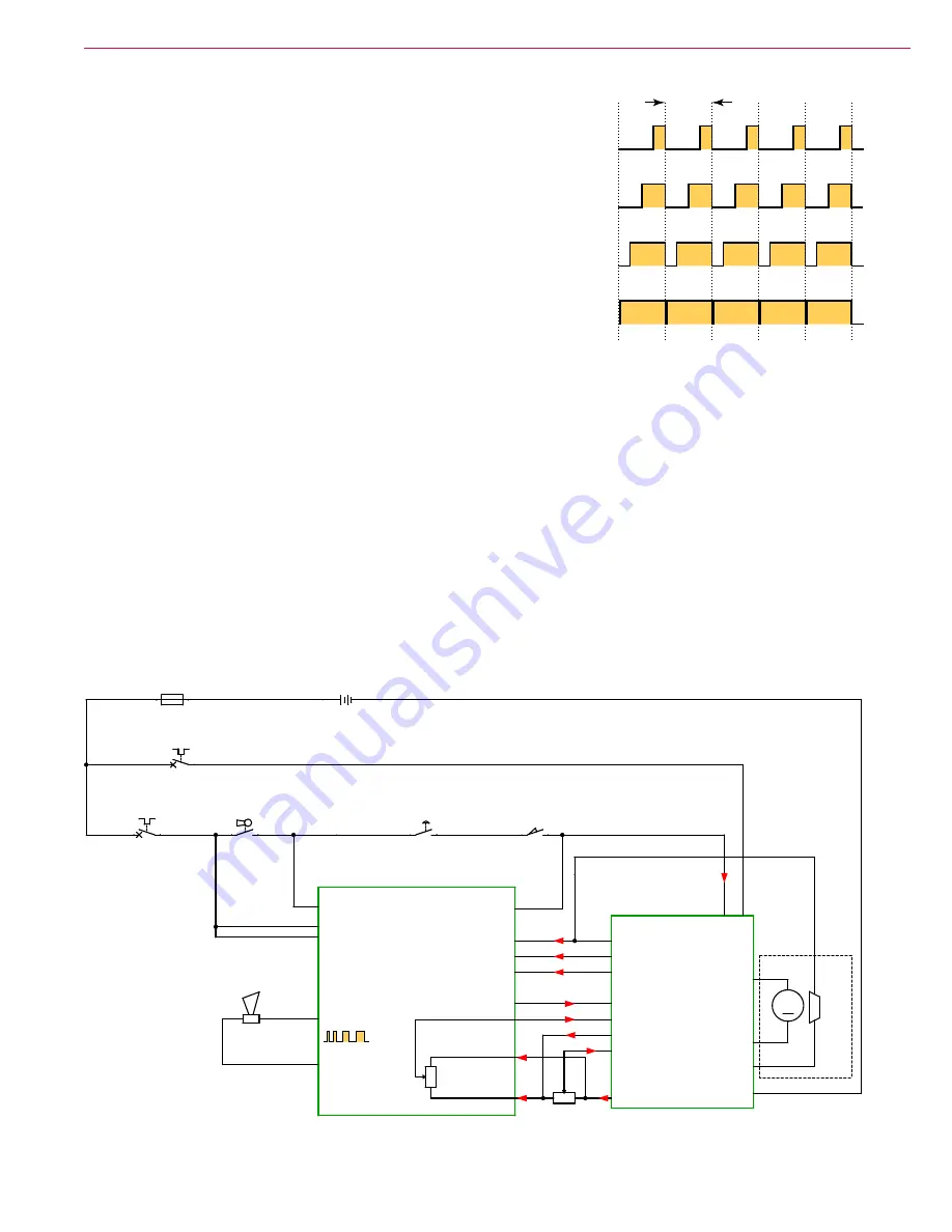
of motor speed control that alters the power to a motor by rapidly turning
the power on and off. The ratio (also called “duty cycle”) between the
On and Off states determines how much power the motor receives. The
shorter the “off-time” the closer to full power the motor will receive. This
switching occurs so fast (15kHz for this controller) that the motor simply
sees it as a reduction in power (voltage) instead of the rapid on/off. PWM
is a standard motor control technique because it is easier to turn power
all the way on and all the way off, than it is to vary the magnitude of the
power. Varying the magnitude would create a lot of heat that would need
to be dissipated.
Drive power
(B+, B-)
is always present at the speed controller
(A2)
from the battery, but the positive battery
input
(B+)
is fused through the circuit breaker
(CB1)
at 70 amps. When the key switch
(S1)
, E-Stop
(S4)
,
and seat switch
(S2)
are closed, 24V control power (enable) is provided to the speed controller via the Brown
wire (Pin 5-KSI). Opening any one of these series connected switches will disable the drive controller. (If the
on-board battery charger is present, its interlock signal is also in series with these switches.)
The two potentiometers (throttle position and speed limit) control the internal “clock” of the controller,
which determines the PWM duty cycle described above. The drive pedal sensor is a physical potentiometer
located in the drive pedal. The speed limit potentiometer is solid state, and located within the Main Machine
Controller. Forward and reverse directions are controlled by a separate connection from the Main Machine
Controller to the Wheel drive controller. The reverse function is active-high. When the reverse line is at low
voltage, the drive controller is in the forward direction, and vice versa.
When the drive is active (either forward or reverse) the Wheel controller pulls the “Brake” output (Motion at
the Main Machine Controller) to GND. This signal is observed by the Main Machine Controller to indicate
that the machine is in motion.
A1 MAIN MACHINE
CONTROLLER
PIN 6 - BRAKE -
PIN 9 - STATUS
PIN 16 - REV. ALARM
PIN 8 - MODE
PIN 18 - SPEED LIMIT
PIN 13 - POT. LOW
PIN 4 - POT. WIPER
PIN 3 - HIGH
PIN 14 - BRAKE +
P
IN
5
-
KS
I
B
+
B-
M1
M2
A2
CURTIS 1228 SPEED
CONTROLLER
J3-1 B+
J3-8 B+
J3-14 KEY SWITCH
SEAT
SWITCH J3-4
MOTION J3-6
STATUS J3-7
REV. ALARM J3-5
SPEED LIMIT J2-4
POT. HIGH J2-6
POT. LOW J2-5
PIN 17 - REVERSE
REVERSE J3-3
S1
KEY SWITCH
1
2
BT1
BATTERY, 24 VDC
+
-
R1 DRIVE
PEDAL SENSOR
C
B
A
M
M1
WHEEL
DRIVE
MOTOR
-
+
CB2
CIRCUIT BREAKER
10 AMP
1
2
Y1
BRAKE
1
2
CB1
CIRCUIT BREAKER, 70A.
1
2
E-STOP
SWITCH
S4
1
2
S2
SEAT SWITCH
2
1
F1
FUSE, 150A.
1
2
H1
HORN
-
+
PWM
25% PWM Duty Cycle
50% PWM Duty Cycle
75% PWM Duty Cycle
100% PWM Duty Cycle
1-Cycle
(15kHz)


