


230
Service Manual – SW5500, FLOORTEC R 985
43 - Sweep System, Side Broom
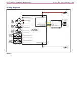
Wiring diagram
RSB+
RSB-
LSB+
LSB-
Right side broom motor +
Right side broom motor -
Left side broom motor +
Left side broom motor -
A2.1
A2.4
A3.1
A3.4
Right side broom actuator /- (1)
Right side broom actuator /- (1)
Left side broom actuator /- (1)
Left side broom actuator /- (1)
BR+
BR-
Main broom motor +
Main broom motor -
MAIN
BROOM
MOTOR
RIGHT SIDE
BROOM
MOTOR
LEFT SIDE
BROOM
MOTOR
M4
M5
M6
B
BATTERY -
J3.1
J3.2
J3.4
J1.1
Dashboard serial connection
Dashboard serial connection
Dashboard el. board power supply -
Return from KEY circuit
J1.2
J1.1 Power +
J2
16
J1.3
J1.4
J1.5
Dashboard serial conn
Dashboard serial connection -
Power -
Power supply enabling
J1.11Drive system board enabling
A2
A3
RIGHT SIDE
BROOM
ACTUATOR
LEFT SIDE
BROOM
ACTUATOR
B+ Main machine controller power
B- Main machine controller power supply -
MAIN MACHINE
CONTROLLER (EB1)
DISPLAY CONTROLLER (EB3)
MAIN CONTROL
BOARD (EB4)
Figure 2: