background image

Engine System

26

Service Manual – PBU Propane Floor Burnisher

Fuel Regulator/Fuel Mixture

This adjustment sets the fuel flow for high and low idle, which determines the fuel to air mixture entering 

the engine  This procedure requires the removal of the anti-tampering caps from the pressure regulator  

Make sure you have a new set of caps available before beginning the procedure 

The procedure below uses the oxygen sensor for evaluating the engine performance  An exhaust gas analyzer 

may be used instead  Use the parameters below if the exhaust gas analyzer is used 

Target CO = 0 007% 

Max  CO = 0 02%

Max  HC = 50 ppm 

NOx = Less than 60 ppm

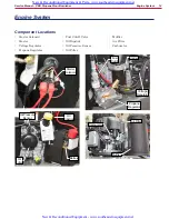
Equipment and Machine Setup

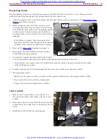
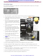
The following steps are required to setup the machine and 

equipment for the testing/adjusting  It will be easier to 

complete these before the engine has warmed up  However, 

you may want to wait until you know that adjustments are 

required before removing the anti-tampering caps on the 

fuel regulator 

1  

Make sure the engine air filter is clean.

2   If the machine is not equipped with the CarbGard 

engine monitoring system (oxygen sensor), remove the 

plug from the exhaust manifold bung and temporarily 

install an oxygen sensor 

3   If the machine is equipped with the CarbGard engine 

monitoring system, unplug the oxygen sensor connector 

and install the voltmeter tap in-line with the original 

connection 

4   Connect a voltmeter between Ground (Battery 

Negative) and the oxygen sensor tap  

•  Set the voltmeter to DC volts and the lowest 

range that is appropriate to read a 0 to 1 

volt signal 

5   Remove the anti-tampering caps from the fuel 

pressure regulator  (You may want to wait 

to complete this step until you know that an 

adjustment is required )

a   Carefully drill a small hole through the center of the 

cap  Take care not to allow the drill bit to damage 

the adjustment screw under the cap 

b   Thread a small sheetmetal or wood screw into the 

hole, and pull the cap off with a pliers 

6   Start the engine and bring it up to operating 

temperature at high idle 

7   Verify that the engine low idle and high idle speeds 

are within normal range as described on page 25  

These speeds will be affected by this procedure, but they 

should be close to begin with  

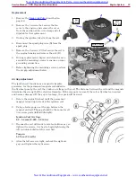
Oxygen 

Sensor

Exhaust 

Manifold Bung

O

2

 Sensor 

Tap

Voltmeter

 Probe

High Idle 

Cover

Low Idle 

Cover

New & Reconditioned Equipment & Parts- www.southeasternequipment.net

New & Reconditioned Equipment - www.southeasternequipment.net

Содержание 56384165

Страница 1: ...384166 PBU 27KACAT 56384167 PBU 21KACATCLDC 56384168 PBU 27KACATCLDC English 21 KACAT Base Model 27 KACAT Base Model 21 KACAT CLDC Dust Control Model 27 KACAT CLDC Dust Control Model New Reconditioned Equipment Parts www southeasternequipment net New Reconditioned Equipment www southeasternequipment net ...

Страница 2: ...older 11 Drive Belt 12 Burnishing Clutch 13 Clutch Switch 13 Engine System 14 Component Locations 14 Maintenance and Adjustments 15 Maintenance Specifications 15 Cooling Air Filter 15 Intake Air Filter 16 Oil and Filter Change 17 Spark Plug Change 18 Troubleshooting 19 Fuel System 24 Throttle Cable Position 24 Throttle High Idle Position 25 Carburetor Low Idle 25 Fuel Regulator Fuel Mixture 26 Low...

Страница 3: ... 37 Valve Clearance 38 Cylinder Head Removal 39 Cylinder Head Cleaning and Inspection 41 Valve Removal 42 Valve and Seat Inspection 42 Cylinder Head Replacement 44 Engine Specifications 46 Special Tools 48 New Reconditioned Equipment Parts www southeasternequipment net New Reconditioned Equipment www southeasternequipment net ...

Страница 4: ...rt number of the machine you are working on to the model numbers listed on the cover page to be sure you are using the correct manual Other Reference Manuals and Information Sources The following documents contain parts information and instructions for machine operation Instructions for Use LT071600_A and LT071500_A Document Revision History April 2015 Initial Release Safety Information Symbols It...

Страница 5: ...ny other propane machine again until cleared by a physician Excessive exposure to CO can result in death Warning Propane is a highly flammable fuel Keep open flames and ignition sources away from the machine and propane tanks Do not store propane cylinders inside a building If you smell propane shut off the machine immediately and take it outside the building Do not use a liquid withdraw propane c...

Страница 6: ...of the primary components of the machine Starter Solenoid Starter Voltage Regulator Propane Regulator Fuel Cutoff Valve Oil Dipstick Oil Pressure Sensor Oil Filter Muffler Air Filter Carburetor Starter Solenoid Battery Oil Dipstick Oil Filter Oil Pressure Sensor Starter Voltage Regulator Propane Regulator Fuel Cutoff Muffler Air Filter Carburetor New Reconditioned Equipment Parts www southeasterne...

Страница 7: ...0 lb 9 1 kg Vapor Withdrawl Auto Fuel Shutoff Yes Yes Yes Yes Low Oil Shutdown Yes Yes Yes Yes Hour Meter Yes Yes Yes Yes Sound Pressure 89 dB A Productivity Rate 25 000 ft2 hr 3 066 m2 hr 33 000 ft2 hr 3 660 m2 hr 25 000 ft2 hr 3 066 m2 hr 33 000 ft2 hr 3 660 m2 hr Agency Approvals EPA UL Approved Propane Comp EPA UL Approved Propane Comp CSA Approved CARB Certified California Air Re source Board...

Страница 8: ...nt Replace air cleaner paper element Check pad driver for loose parts Check belt for wear or slippage Check engine pulley for tightness Check wheel bolts Check engine mount bolts Check handle bolts Check for leakage of engine oil at the various seals Change dust control filter Check and adjust engine valve clearance Clean and lap valve seating surface Clean dust and dirt from cylinder and cylinder...

Страница 9: ...drive pulley when not in use The clutch is electrically actuated and controlled by a switch on the operator s handle Units equipped with dust control have an aluminum shroud which covers most of the burnisher drive components Component Locations Burnishing Disk Pulley Tensioner Idler Pulley Drive Belt Engine Shaft Drive Pulley Drive Pulley with Clutch Burnishing Disk Pulley Drive Belt Tensioner Id...

Страница 10: ...bleshooting Clutch Circuit Troubleshooting 1 Check that the battery voltage is at least 12 volts If below 12 volts troubleshoot the battery and charging system first 2 Disconnect the clutch cable connector and measure the resistance of the coil If the resistance is outside of the range of 2 5 to 3 1 ohms replace the coil 3 Next check for an open circuit with the key switch in the on position and t...

Страница 11: ...pane service valve and remove the propane tank 2 Stand the machine on its back in the pad change position 3 Remove the burnishing pad from the pad holder 4 Place a 3 4 open end wrench on the top of the burnishing shaft to hold the shaft from turning 5 Wear gloves to protect your hands from the gripping spines on the pad holder 6 Unscrew the pad holder from the shaft in a normal counterclockwise di...

Страница 12: ...olt Burnishing Pad Shaft 4 Place a 9 16 box wrench on the idler pulley shaft bolt and rotate the tensioning arm counterclockwise to de tension the drive belt 5 Roll the belt off the main pulley It may be helpful to use a screw driver to get it started 6 Remove the belt from the engine pulley For Dust Control models remove the belt from above the dust shroud by pulling it out toward the engine pull...

Страница 13: ...e connector located behind the propane regulator 5 Loosen the 3 engine mounting bolts just enough to raise the engine and extract the clutch cable through the opening in the deck Alternatively you could remove the clutch wires from the cable connector and remove the cable without lifting the engine 6 Finish removing the clutch retaining bolt and remove the clutch from the motor shaft 7 During repl...

Страница 14: ...utoff Valve Oil Dipstick Oil Pressure Sensor Oil Filter Muffler Air Filter Carburetor Starter Solenoid Battery Oil Dipstick Oil Filter Oil Pressure Sensor Starter Voltage Regulator Propane Regulator Fuel Cutoff Muffler Air Filter Carburetor New Reconditioned Equipment Parts www southeasternequipment net New Reconditioned Equipment www southeasternequipment net ...

Страница 15: ... Spark Plug Gap 0 6 mm 0 025 in Spark Plug Torque 22 N m 16 ft lb Coil Air Gap 0 2 0 4 mm 0 008 0 016 in page 33 Valve Clearance 0 10 0 15 mm 0 004 0 006 in page 38 Min Cyl Compression 483 kPa 70 psi page 35 Cooling Air Filter The cooling filter should be cleaned every 1 engine hour It is also a good practice to clean the cooling air filter when ever the machine is serviced Restrictions in the air...

Страница 16: ...filter off the main filter The pre filter may be washed with mild soap dish soap and water 4 Thoroughly dry the pre filter Do not wring the filter as this can tear the foam Do not install the pre filter over the main filter unless it is completely dry Moisture from the pre filter can damage the paper of the main filter Replace the pre filter if it becomes torn or damaged 5 If the main filter is re...

Страница 17: ...as possible until the tube stops dripping 7 Close the quick release valve remove the tube and replace the drain cap 8 If the oil filter is not being changed skip to step 14 below 9 Slightly loosen the oil filter using a small oil filter wrench If necessary disconnect the oil pressure sensor wires to avoid bending the terminals 10 Tilt the burnisher slightly on its left side to avoid dripping oil o...

Страница 18: ...nsumption 1 Cylinder 2 Cylinder Plug Wire Boot Plug Wire Boot Plug Type Quantity 2 NGK BPR4ES Plug Gap 0 6 mm 0 025 in Socket Size 13 16 inch 1 Pull the plug wire boot off the spark plug Take care not to pull the boot from the wire 2 Using a 13 16 spark plug socket remove the spark plug from the cylinder 3 Inspect the gap on the new plugs The manufacturer s default gap is 0 032 0 8 mm which is bey...

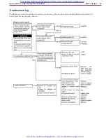
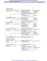
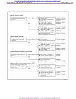
Страница 19: ...shooting The following troubleshooting decision tree is courtesy of Kawasaki and contains information relating to both gasoline and propane engines New Reconditioned Equipment Parts www southeasternequipment net New Reconditioned Equipment www southeasternequipment net ...

Страница 20: ...Engine System 20 Service Manual PBU Propane Floor Burnisher New Reconditioned Equipment Parts www southeasternequipment net New Reconditioned Equipment www southeasternequipment net ...

Страница 21: ...Engine System 21 Service Manual PBU Propane Floor Burnisher New Reconditioned Equipment Parts www southeasternequipment net New Reconditioned Equipment www southeasternequipment net ...

Страница 22: ...Engine System 22 Service Manual PBU Propane Floor Burnisher New Reconditioned Equipment Parts www southeasternequipment net New Reconditioned Equipment www southeasternequipment net ...

Страница 23: ...Engine System 23 Service Manual PBU Propane Floor Burnisher New Reconditioned Equipment Parts www southeasternequipment net New Reconditioned Equipment www southeasternequipment net ...

Страница 24: ...is controlled by the mechanical governor The governor is inside the engine and operates on centrifugal force The faster the engine turns the more the governor tries to close the carburetor s butterfly valve Conversely a spring connected to the operator s throttle position lever tries to pull the butterfly valve open When these two forces are balanced the engine will run at constant speed even when...

Страница 25: ...tighten the jamb nut Carburetor Low Idle Unlike the High Idle Position that indirectly controls the engine RPM via the governor the Low Idle adjustment acts directly on the carburetor butterfly valve to set the minimum butterfly position for engine idle This adjustment may be completed on its own or as a followup adjustment to adjusting the fuel mixture described on page 26 1 Make sure the Throttl...

Страница 26: ...g from the exhaust manifold bung and temporarily install an oxygen sensor 3 If the machine is equipped with the CarbGard engine monitoring system unplug the oxygen sensor connector and install the voltmeter tap in line with the original connection 4 Connect a voltmeter between Ground Battery Negative and the oxygen sensor tap Set the voltmeter to DC volts and the lowest range that is appropriate t...

Страница 27: ...d on a floor surface 2 While the machine is loaded observe the voltage reading from the oxygen sensor The voltmeter reading should be between 50 and 60 mV 0 050 to 0 060 V 3 If the oxygen sensor voltage is out of range turn the high limit fuel adjustment screw triangular head screw in 1 4 turn increments Loosen the setscrew on the back of the outlet that locks the adjustment screw Low Voltage Turn...

Страница 28: ...r arm 5 Disconnect the butterfly link and spring from the governor arm 6 Remove the nut A and screw B that secure the throttle plate to the manifold and remove the throttle plate If you prefer to completely remove the throttle plate from the machine remove the throttle cable as you remove the throttle plate 7 Remove the 4 screws that secure the intake manifold to the heads and remove the manifold ...

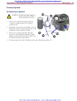
Страница 29: ... Optionally remove the bolt washers and nut D that secures the support bracket C to the muffler A and remove the bracket 3 Remove the 4 nuts and washers E that secure the manifold to the cylinder exhaust flanges and carefully lower the exhaust from the studs and remove the exhaust 4 During replacement clean the flanges and replace the flange gaskets F B C E F D A New Reconditioned Equipment Parts ...

Страница 30: ... engage with the engine it is typically the bendix drive or pinion gear that are damaged 1 To avoid accidental shorting of the starter wire remove the battery negative terminal from the battery 2 Remove the two bolts that secure the starter to the engine housing and lower the starter to remove it 3 Remove the nut that secures the power wire to the motor terminal and remove the wire 4 Inspect the p...

Страница 31: ...h idle 3 With a voltmeter set to AC volts measure the voltage between terminals A and B The voltage should be between 26 to 34 volts AC 4 Set the voltmeter to DC volts and check the voltage between terminal C and Ground This voltage should be between 13 to 15 volts DC If the voltage is outside of this range then replace the voltage regulator Replacement 1 Disconnect the generator connector from Te...

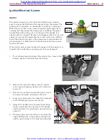
Страница 32: ... will likely receive a shock 2 With the fuel service valve closed check for spark by cranking the engine for no more than a couple seconds at a time If an ignition spark tester is available connect one end of the spark tester to the spark plug wire and the other end to a good ground Crank the engine and look for a spark at the tester If an ignition spark tester is not available use a fresh spark p...

Страница 33: ...wheel pass by the coil they induce a voltage in the coil The distance between the coil and the magnets determine the strength of the electrical impulse If the air gap is too small the coil or flywheel can contact and become damaged If the gap is too large the spark will be weak 1 Rotate the engine flywheel until the permanent magnet is lined up in front of the ignition coil 2 Using a feeler gauge ...

Страница 34: ...o send a signal The oxygen sensor creates a small voltage based on the amount of oxygen present The sensor s output ranges from 0 1 volts lean to 0 9 volts rich The output of the CarbGard module acts like a switch in the engine safety circuit When the switch is closed the circuit is complete and the electric fuel lockout valve will be open to permit fuel to the engine The CarbGard switch is in ser...

Страница 35: ...alve in the carburetor wide open to permit maximum air to enter the cylinder 6 Remove both spark plugs from their cylinders 7 Thread the compression tester into the first spark plug port It is not necessary to tighten the gauge with tools Use firm hand tightening until the gauge is fully seated Make sure the gauge is reading zero before you begin Press the pressure release button to release pressu...

Страница 36: ...ional oil will improve a poor piston ring seal but will not improve the seal from a bad valve Important For this test to be successful the small amount of oil must evenly spread across the face of the piston So the machine must be tipped up so that the cylinder is pointing upward It cannot be completed in a horizontal position 1 Tip the machine up so the tested cylinder is facing upward 2 Using a ...

Страница 37: ...e wire clamp and oil dipstick for the replacement Valve Cover 1 Remove the 5 screws that secure the valve cover to the head and remove the valve cover 2 During replacement clean the gasket sealing surfaces and install a new gasket 3 When installing the valve cover tighten the screws in the sequence shown Torque Valve Cover Screws 5 9 N m 52 in lb Air Filter Oil Dipstick Wire Clamp 1 4 2 5 3 Valve ...

Страница 38: ...ot loose the engine is not on the compression stroke and needs to be turned one full revolution more 7 You will need to repeat this for each of the two cylinders while adjusting their respective valves 8 While holding the adjustment bolt from turning loosen the lock nut 9 Insert a 0 13 mm 005 feeler gauge between the rocker arm and valve Valve Clearance Cold Intake Exhaust 0 10 0 15 mm 0 004 0 006...

Страница 39: ...cribed on page 28 5 Remove the spark plugs 6 Remove the screws D that secures the wire clamp E to the 1 cylinder and move the wires aside 7 Remove the screw F that secures the lifting hook G to the 2 cylinder and remove the hook 8 Disconnect the Ground wire Battery Positive and AC Input wires from the voltage regulator 9 Remove the 2 screws C that secure the cylinder cooling shrouds to the cylinde...

Страница 40: ...er arms Label the rocker arms for replacement on the same valves during reassembly 13 Lift out the push rods Label the push rods for replacement under the same rocker arms during reassembly 14 Loosen the 5 head bolts 1 4 turn in the sequence shown to reduce the likelihood of warping the heads 15 Finish removing the 5 head bolts and carefully lift the head away from the cylinder 16 Continue on with...

Страница 41: ...cks not visible to the eye may be detected by coating the suspected area with mixture of 25 kerosene and 75 light engine oil Wipe the area dry and immediately apply a coating of zinc oxide dissolved in wood alcohol If a crack is present the coating will become discolored at the defective area 4 If a crack is present in the cylinder head replace it 5 Inspect the mating surface for burrs and nicks 6...

Страница 42: ...d beyond reconditioning replace the cylinder head with a new one Pitted or worn valve seats can be refaced with a seat cutter After refacing lap the valves to the seats 2 Inspect the seating pattern and width Note The valve stem and guide must be in good condition or this check will not be valid a Coat the valve seat with machinist s dye b Push the valve into the guide c Rotate the valve against t...

Страница 43: ...rs Valve Margin Service Limit Intake Exhaust 0 35 mm 0 0138 in Valve Stem Runout Service Limit Intake Exhaust TIR 0 05 mm 0 002 in Valve Stem Diameter Measure the diameter of the valve stem in two directions at right angles at four different positions on the stem Valve Stem Diameter Service Limit Inlet 5 95 mm 0 234 in Exhaust 5 93 mm 0 233 in Seat Width Stem Margin Face Head Margin New Reconditio...

Страница 44: ...ting surfaces are clean and place a new head gasket on the cylinder 3 Double check to make sure no debris has fallen into the cylinder It is best to raise the piston to top dead center which will also be needed for replacing the rocker arms later 4 Without disturbing the gasket place the head on the cylinder and install the 5 head bolts finger tight only 5 Begin tightening the head bolts in the cr...

Страница 45: ... arm bolt 11 Insert the rocker arm bolt J through the bracket and into the eccentric collar K Make sure to align the flat on the bolt with the flat on the collar On the 1 cylinder insert the bolts with the head pointing up On the 2 cylinder insert the bolts with the head pointing down 12 Install the locking nut H on the rocker arm bolt but leave it slightly loose 13 Set the Valve Clearance describ...

Страница 46: ...ight all speed governor Lubrication System Pressure feed by positive displacement pump Oil Type 30HD or 10W30 API rating SJ or higher Oil Filter Cartridge type full flow filter Oil Capacity when engine is completely dry 2 0 L 2 1 US qt Cooling System Forced air cooling by fan Dimensions L W H 486 mm 429 mm 362 mm 19 1 in 16 9 in 14 3 in Dry Weight without muffler 36 7 kg 80 9 lb Specifications are...

Страница 47: ...ameter 15 96 mm 0 628 in Piston Pin Hole Inside Diameter 16 08 mm 0 633 in Connecting Rod Small End Inside Diameter 16 05 mm 0 632 in Cylinder Inside Diameter Standard Cylinder 73 10 mm 2 878 in 0 50 mm Oversize Cylinder 73 60 mm 2 898 in Cylinder Inside Diameter Out Round 0 05 mm 0 002 in Valve Clearance Intake Exhaust 0 10 0 15 mm 0 004 0 006 in Valve Seating Surface Angle Intake Exhaust 45 Valv...

Страница 48: ...tems that are equipped with CarbGard The volt meter has a special probe to connect to the oxygen sensor tap Tachometer Volt Meter Probes O2 Sensor O2 Sensor Tap Volt Meter Exhaust Analyzer The exhaust analyzer may be used in place of the fuel mixture kit to adjust the fuel mixture based on carbon monoxide values New Reconditioned Equipment Parts www southeasternequipment net New Reconditioned Equi...

Отзывы: