background image

XAR17ARDA001G/E

96

Return to previous page

8 . Attach the tension jig (30670-2100) to the 

measuring unit ASSY (30601-3000). 

9 . Turn FC4 × 10 of the tension jig (30670-

2100) to adjust the tension of the wire 
(30601-M307) so that the focus base 
ASSY (30601-3300) moves smoothly.

10. Fasten the pulley 2 ASSY (30601-3120) 

with BS3 × 6 (n = 2).

11 . Perform AR CALIBRATION 

(see 8.7 

[p130])

.

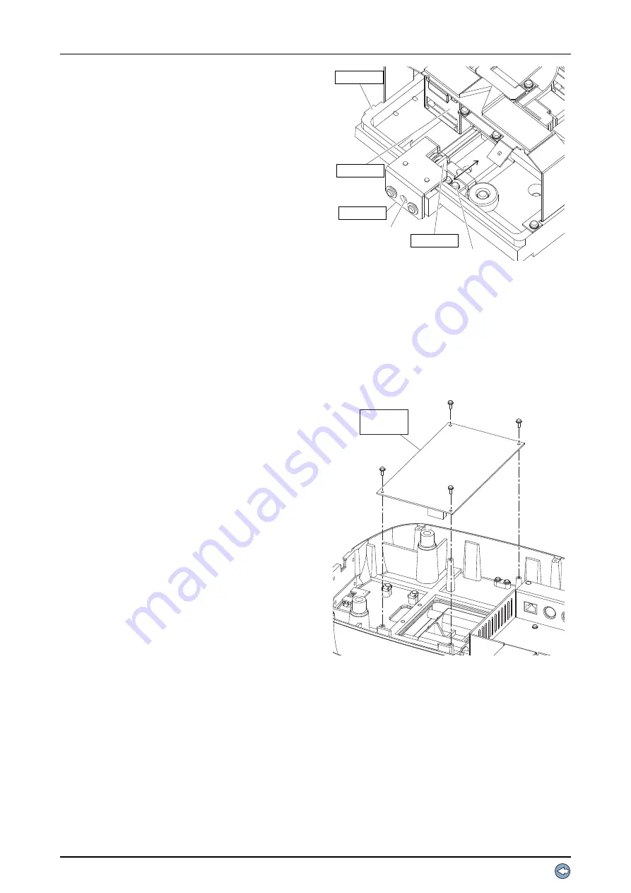
7.3.20  Switching power supply (80602-00102)

Replacement part: 80602-00102

1 . Remove the bottom plate (30601-M002) 

(see 6.7 [p66])

.

2 . Unscrew BS3 × 8 (n = 4) to replace the 

switching power supply (80602-00102).

3 . Reassemble the parts in the reverse order.

$5˜

(%˜

$5˜

Содержание AR-310A

Страница 1: ...AUTO REFRACTOMETER AUTO REF KERATOMETER AR 310A AR 330A AR 360A ARK 510A ARK 530A ARK 560A SERVICE MANUAL September 2014 Pages in total 218 XAR17ARDA001G E ...

Страница 2: ......

Страница 3: ...OUT 25 5 2 6 ERR013 Receiving error OUT 25 5 2 7 ERR014 Receiving code error OUT 25 5 2 8 ERR015 Reply time out OUT 25 5 2 9 ERR016 DTR DSR error OUT 25 5 2 10 ERR017 Data error OUT 25 5 2 11 ERR018 Command error OUT 25 5 2 12 NO DAT Data empty OUT 25 5 2 13 ERR021 Time out error in characters IN 25 5 2 14 ERR022 Time out error for receiving data IN 25 5 2 15 ERR023 Receiving error IN 25 5 2 16 ER...

Страница 4: ...ation 38 5 2 50 ERR761 Access right error 39 5 2 51 ERR762 Account error 39 5 2 52 ERR771 Cable connection error 39 5 2 53 ERR772 Reply error 39 5 3 Function Buttons are not Operational 40 5 4 Measuring Unit does not Move Smoothly along Base Unit 41 5 5 Rotating Joystick does not Move Measuring Unit Up or Down 42 5 6 Chinrest does not Move Up or Down 44 5 7 Measurement cannot be Performed Properly...

Страница 5: ...LACEMENT PROCEDURE 69 7 1 ASSYs 69 7 1 1 Joystick ASSY 30601 2600 69 7 1 2 Measuring ASSY 30601 9E00 70 7 1 3 Phototransmitter ASSY 30601 3310 70 7 1 4 Mire ASSY 30601 4000 71 7 1 5 LCD ASSY 30601 6100 71 7 1 6 Subjective cylinder ASSY 30703 3700 72 7 1 7 Chart disk ASSY 30703 3800 72 7 2 Boards 73 7 2 1 Main board 73 7 2 2 Tracking board 30601 BA02 74 7 2 3 Driver board 30601 BA03 75 7 2 4 Base b...

Страница 6: ...s 98 7 4 1 R L shaft 30601 M201 98 7 4 2 F B shaft 30601 M103 99 7 4 3 Sliding plate 32105 M102 99 7 4 4 Wire 30601 M307 100 7 4 5 Linear bearing 101 7 4 5 1 Linear bearing for F B shafts 82001 LM028 101 7 4 5 2 Linear bearing for R L shaft 82001 LM097 101 8 ADJUSTMENT 103 8 1 Entering Adjustment Mode 103 8 1 1 MENU mode 103 8 1 2 CALIB MODE SELECT for AR 104 8 1 3 ALIGNMENT CALIBRATION 104 8 1 4 ...

Страница 7: ...5 2 AR 360A ARK 560A 125 8 5 2 1 Subjective cylinder ASSY adjustment 125 8 5 2 2 Chart position adjustment 127 8 6 ALIGNMENT CALIBRATION 129 8 7 AR CALIBRATION 130 8 7 1 AR CALIBRATION 130 8 7 2 AR AXIS 132 8 7 3 AXIS OFFSET 133 8 7 4 SPH OFFSET 134 8 7 5 CHART CALIBRATION 135 8 7 5 1 AR 310A AR 330A ARK 510A ARK 530A 135 8 7 5 1 1 Chart test jig 135 8 7 5 1 2 Diopter tester jig ASSY 138 8 7 5 2 A...

Страница 8: ...A and ARK 530A 185 9 3 1 2 30601 E000 AR 310A and ARK 510A 186 9 3 1 3 30603 E000 AR 360A and 30703 E000 ARK 560A 187 9 3 2 Partial writing diagram 188 9 4 Error Messages 202 9 5 Parameter List 204 9 5 1 AR 310A AR 330A 204 9 5 2 AR 360A 206 9 5 3 ARK 510A ARK 530A 208 9 5 4 ARK 560A 210 9 6 Jig List 212 9 7 Adjustment Item List 213 9 7 1 ASSYs boards and adjustment items 213 9 7 2 Electrical comp...

Страница 9: ...orough understanding of the contents in this manual is required prior to the service Refer to the Operator s Manual and Parts List for the AR 310A AR 330A AR 360A ARK 510A ARK 530A and ARK 560A In case the device cannot be repaired according to the procedures described in this manual please report the serial number of the device and details of the symptom or symptoms Refer to the Service Manual An...

Страница 10: ...XAR17ARDA001G E 10 Return to previous page This page is intentionally left blank ...

Страница 11: ... is classified as a Class 1 laser product indicating that the part does not emit hazardous irradiation to the eye 3 Cautions regarding power source and power cord 1 Disconnect the power cord by holding its plug Do not place heavy objects on the cord or coil the cord tightly A damaged power cord may cause fire or electric shock 2 Occasionally clean the prongs of the power plug with a dry cloth If d...

Страница 12: ...precautions against electric shock 11 When a cable with any of the following marks is disconnected and reconnected be sure to confirm that the screws are tightened securely a Protective ground b Functional ground c Equipotential 12 Install the device where the outlet which the power plug is inserted into is easily accessible during use In addition ensure that the power plug can be disconnected wit...

Страница 13: ...he AR 310A AR 330A AR 360A ARK 510A ARK 530A and ARK 560A conform to the EMC standard of IEC60601 1 2 2007 4 Degree of protection against harmful ingress of water IPX0 The AR 310A AR 330A AR 360A ARK 510A ARK 530A and ARK 560A provide no protection against ingress of water with harmful effects Avoid splashing water or other liquids on or near these devices 5 Degree of safety for application in the...

Страница 14: ...5 00 to 13 00 mm 0 01 mm increments Corneal refractive power R1 R2 AVE 25 96 to 67 50 D n 1 3375 0 01 0 12 0 25 D increments n 1 3375 1 336 1 332 Corneal cylindrical power CYL 12 00 to 12 00 D 0 01 0 12 0 25 D increments Cylinder axis A 0 to 180 1 5 increments KM measurable area ø3 3 mm for mire ring corneal curvature radius of 7 7 mm ø6 0 mm for four points corneal curvature radius of 7 7 mm Size...

Страница 15: ...0 40 20 30 20 25 20 20 0 1 or lower 0 1 0 25 0 32 0 4 0 5 0 63 0 8 1 0 8 Uncorrected visual acuity measurement AR 360A ARK 560A Measurement range 20 200 or lower 20 200 20 80 20 60 20 50 20 40 20 30 20 25 20 20 0 1 or lower 0 1 0 25 0 32 0 4 0 5 0 63 0 8 1 0 Chart VA 20 200 20 80 20 60 20 50 20 40 20 30 20 25 20 20 or 20 200 to 20 20 entire VA 0 1 0 25 0 32 0 4 0 5 0 63 0 8 1 0 or 0 1 to 1 0 entir...

Страница 16: ...50 to 95 F Humidity 30 to 90ºC No condensation Athmospheric pressure 800 to 1060 hPa 14 Environmental conditions during transport and storage in packed condition Temperature 10 to 55ºC 14 to 131 F Humidity 10 to 95ºC No condensation Athmospheric pressure 700 to 1060 hPa 15 Others Service life 8 years from the date of initial operation certified Regular check maintenance and consumable parts replac...

Страница 17: ... operated No 5 3 Function Buttons are not Operational p40 Yes Does the main unit move horizontally No 5 4 Measuring Unit does not Move Smoothly along Base Unit p41 Yes Does rotating the joystick move the measuring unit up and down No 5 5 Rotating Joystick does not Move Measuring Unit Up or Down p42 Yes Does the chinrest move up and down smoothly No 5 6 Chinrest does not Move Up or Down p44 Yes Can...

Страница 18: ...rformed properly No 5 8 Communication cannot be Performed Properly p60 Yes Can printing be performed No 5 9 Printing cannot be Performed p60 Yes Does the LCD auto sleep function operate No 5 10 LCD Auto Sleep Function does not Operate p61 Yes Turn off the power switch ...

Страница 19: ... 2 p74 Yes Are there any breaks in the BA01 BA03 cable 30601 EA13 see 9 3 p185 Yes Replace the BA01 BA03 cable 30601 EA13 No Are there any breaks in the flexible flat cable 30601 E022 see 9 3 p185 Yes Replace the flexible flat cable 30601 E022 No Does the backlight of the color LCD 30601 E005 light up No 5 1 2 Backlight of color LCD does not light up p21 Yes Are there any breaks in the flexible fl...

Страница 20: ...n the J51 4th and 1st 5th and 2nd and 6th and 3rd pins on the switching power supply 80602 00102 DC 15 V see 9 3 p185 No Replace the Switching power supply 80602 00102 see 7 3 20 p96 Yes Are there any breaks in the power supply output cable 30601 EA51 see 9 3 p185 Yes Replace the power supply output cable 30601 EA51 No Are there any breaks in the base cable 30601 EA52 see 9 3 p185 Yes Replace the ...

Страница 21: ...aks in the BA01 BA03 cable 30601 EA13 see 9 3 p185 Yes Replace the BA01 BA03 cable 30601 EA13 No Are there any breaks in the flexible flat cable 30601 E022 see 9 3 p185 Yes Replace the flexible flat cable 30601 E022 No Are there any breaks in the FL inverter cable 30601 EA63 see 9 3 p185 Yes Replace the FL inverter cable 30601 EA63 No Replace the DC AC inverter 18535 E010 see 7 2 11 p81 Is the pro...

Страница 22: ... p103 Yes Perform adjustment and calibration according to the error contents No Rewrite the EEPROM data of the driver board 30601 BA03 see 8 15 p173 Is the problem resolved Yes End No Replace the Driver board 30601 BA03 see 7 2 3 p75 Set the time and date see 8 13 p171 In about 30 minutes turn off and on the power switch Does ERR002 occur No End Yes Replace the Main board see 7 2 1 p73 ...

Страница 23: ...orm for the driver board 30601 BA03 IC20 1st pin and P310 J1 1st pin trigger side forms two peak see 9 3 p187 No Replace the BA08 PD CCD board 32105 BA08 see 7 2 10 1 p80 Yes Replace the Driver board 30601 BA03 see 7 2 3 p75 Are there any breaks in the BA01 BA03 cable 30601 EA13 see 9 3 p187 Yes Replace the BA01 BA03 cable 30601 EA13 No Are there any breaks in the base cable 30601 EA52 see 9 3 p18...

Страница 24: ...he operator s manual of the connected device Yes Are there any breaks in the base cable 30601 EA52 see 9 3 p185 Yes Replace the base cable 30601 EA52 No Replace the Base board 30601 BA05 see 7 2 4 p76 Is the problem resolved No End Yes Replace the Main board see 7 2 1 p73 Is the problem resolved No The connected device is defective Refer to the service manual for the connected device Yes End ...

Страница 25: ... as in 5 2 4 ERR011 Time out error in characters OUT p24 5 2 11 ERR018 Command error OUT Perform the procedure as in 5 2 4 ERR011 Time out error in characters OUT p24 5 2 12 NO DAT Data empty OUT Perform the measurement then confirm that the data displayed is the measurement data 5 2 13 ERR021 Time out error in characters IN Perform the procedure as in 5 2 4 ERR011 Time out error in characters OUT...

Страница 26: ...4 5 2 19 ERR027 Data error IN Perform the procedure as in 5 2 4 ERR011 Time out error in characters OUT p24 5 2 20 ERR028 Command error IN Perform the procedure as in 5 2 4 ERR011 Time out error in characters OUT p24 5 2 21 ERR031 Up and down tracking error Perform the procedure as in 5 5 Rotating Joystick does not Move Measuring Unit Up or Down p42 ...

Страница 27: ...ensor of the R L sensor 30602 EA20 is shaded see 9 3 p185 R L position sensor 2nd and 4th pins When shaded DC 0 V When not shaded DC 5 V R L limit sensor 3rd and 4th pins When shaded DC 0 V When not shaded DC 5 V No Replace the R L sensor 30602 EA20 see 7 3 1 p82 Yes Are there any breaks in the BA02 BA03 cable 30601 EA24 see 9 3 p185 Yes Replace the BA02 BA03 cable 30601 EA24 No Replace the Tracki...

Страница 28: ... the following pins of P210 J10 on the tracking board 30601 BA02 as shown below when each sensor of the F B sensor 30602 EA21 is shaded see 9 3 p185 F B position sensor 2nd and 4th pins When shaded DC 0 V When not shaded DC 5 V F B limit sensor 3rd and 4th pins When shaded DC 0 V When not shaded DC 5 V No Replace the F B sensor 30602 EA21 see 7 3 2 p82 Yes Are there any breaks in the BA02 BA03 cab...

Страница 29: ... BA03 DC 5 V see 9 3 p185 No Replace the Driver board 30601 BA03 see 7 2 3 p75 Yes Are there any breaks in the printer power supply cable 30601 EA31 see 9 3 p185 Yes Replace the printer power supply cable 30601 EA31 No Are there any breaks in the printer cable 30601 EA32 see 9 3 p185 Yes Replace the printer cable 30601 EA32 No Replace the Printer interface board 80606 00019 see 7 2 12 p81 Is the p...

Страница 30: ...601 M307 Yes Replace the Wire 30601 M307 see 7 4 4 p100 No Are there any breaks in the sensor motor 30601 EA35 see 9 3 p185 Yes Replace the Sensor motor 30601 E035 see 7 3 19 p95 No Is the voltage between the P306 J6 3rd and 4th pins on the driver board 30601 BA03 as shown below when the sensor of the sensor origin 30601 EA36 is shaded When shaded DC 5 V When not shaded DC 0 V No Replace the Origi...

Страница 31: ... motor cable 30601 EA34 Yes Replace the Brushless motor 30601 E011 see 7 3 18 p94 Is the problem resolved Yes End No Replace the Driver board 30601 BA03 see 7 2 3 p75 Are there any breaks in the CL motor 30703 EA37 see 9 3 p185 Yes Replace the CL motor 30703 EA37 see 7 3 8 p86 No Are there any breaks in the CL sensor 30703 EA38 see 9 3 p185 Yes Replace the CL sensor 30703 EA38 see 7 3 9 p87 No Rep...

Страница 32: ...e chart 30703 EA74 see 9 3 p185 Yes Replace the Chart 30703 EA74 see 7 3 15 p92 No Replace the Driver board 30601 BA03 see 7 2 3 p75 Is the problem resolved Yes End No Replace the Main board see 7 2 1 p73 Replace the Eye Care card Is the problem resolved No Replace the Base board 30601 BA05 see 7 2 4 p76 Yes End Reinsert the Eye Care card for writing Does ERR502 appear Yes Replace the card No End ...

Страница 33: ...es other than the optional barcode scanner connected to the device Yes Remove the connected USB device except the USB flash drive for upgrade No Replace the Main board see 7 2 1 p73 Reconnect the USB device then restart the device Is the problem resolved Yes End No Connect other USB device Does ERR602 occur No Replace the USB device Yes Replace the Base board 30601 BA05 see 7 2 4 p76 Is the proble...

Страница 34: ...t operate normally Or set the DHCP connection to OFF to set the IP address and subnet mask see 8 16 p174 Is the LAN cable connected to the LAN port No Connect the LAN cable Yes Is the network setting correct No Correct the network setting see 8 16 p174 Yes Contact the network administrator Turn off the power switch of the device then turn it on again Is the problem resolved Yes End No Replace the ...

Страница 35: ...twork setting correct No Correct the network setting see 8 16 p174 Yes Are there any breaks in the LAN cable Yes Replace the LAN cable No Are there any breaks in the base cable 30601 EA52 see 9 3 p185 Yes Replace the base cable 30601 EA52 No Replace the Base board 30601 BA05 see 7 2 4 p76 Is the problem resolved Yes End No Replace the Main board see 7 2 1 p73 ...

Страница 36: ...shared folder Yes Is the name of the folder in the destination PC the same as that of the folder in the device No Correct the network setting see 8 16 p174 Yes Is write access to the shared folder enabled No Enable write access to the shared folder Yes Is there enough free space on the drive containing the shared folder No Free up space on the drive Yes Contact the network administrator ...

Страница 37: ...cable connected to the LAN port No Connect the LAN cable Yes Is the network setting correct No Correct the network setting see 8 16 p174 Yes Are there any breaks in the LAN cable Yes Replace the LAN cable No Is the destination PC connected by LAN No Connect the destination PC by LAN Yes Is the network setting of the destination PC correct No Correct the network setting of the destination PC see 8 ...

Страница 38: ...ting correct No Enter the correct user name in the user name field of the network setting see 8 16 p174 Yes Is the password entered in the password field of the network setting correct No Enter the correct password in the password field of the network setting see 8 16 p174 Yes Is the user account setting of the destination PC correct No Correct the user account setting of the destination PC Yes Co...

Страница 39: ...r The data reception software NAVIS in the PC could not delete the data within the specified time 5 seconds after data reception Check the setting of the data reception software NAVIS in the PC Is the LAN cable connected to the LAN port No Connect the LAN cable Yes Are there any breaks in the LAN cable Yes Replace the LAN cable No Are there any breaks in the base cable 30601 EA52 see 9 3 p185 Yes ...

Страница 40: ...0601 BA15 when each switch on the panel is pressed see 9 3 p185 SW1 1st and 2nd pins SW2 1st and 3rd pins SW3 1st and 4th pins SW4 1st and 5th pins No Replace the Right panel SW board 30601 BA15 see 7 2 9 p79 Yes Are there any breaks in the BA07 cable 30601 EA64 see 9 3 p185 Yes Replace the BA07 cable 30601 EA64 No Are there any breaks in the BA15 cable 30601 EA65 see 9 3 p185 Yes Replace the BA15...

Страница 41: ...othly to the right left forward and backward No Replace the Sliding plate 32105 M102 see 7 4 3 p99 Yes Does the measuring unit move smoothly to the right and left No Replace the R L shaft 30601 M201 see 7 4 1 p98 Replace the Linear bearing for R L shaft 82001 LM097 see 7 4 5 2 p101 Yes Replace the F B shaft 30601 M103 see 7 4 2 p99 Replace the Linear bearing for F B shafts 82001 LM028 see 7 4 5 1 ...

Страница 42: ... the Joystick ASSY 30601 2600 see 7 1 1 p69 Yes Are there any breaks in the BA02 power supply cable 30601 EA11 see 9 3 p185 Yes Replace the BA02 power supply cable 30601 EA11 No Are the voltages between the following pins of P211 J11 on the tracking board 30601 BA02 as shown below when each sensor of the U D sensor 30602 EA22 is shaded see 9 3 p185 Up limit sensor 3rd and 4th pins When shaded DC 0...

Страница 43: ...XAR17ARDA001G E 43 Return to previous page Replace the U D motor 30601 EA28 see 7 3 6 p85 Is the problem resolved No Replace the Main board see 7 2 1 p73 Yes End ...

Страница 44: ...e the U D SW board 30601 BA09 see 7 2 7 p78 Yes Are there any breaks in the BA02 BA03 cable 30601 EA24 see 9 3 p185 Yes Replace the BA02 BA03 cable 30601 EA24 No Are there any breaks in the chinrest cable 30601 EA54 see 9 3 p185 Yes Replace the chinrest cable 30601 EA54 No Is there any breaks in the chinrest 30601 EA53 see 9 3 p185 Yes Replace the Chinrest 30601 EA53 see 7 3 12 p89 No Are there an...

Страница 45: ...12 p89 Yes Are the voltages between the following pins of P102 J2 on the main board 30601 BA01 as shown below when the up down button is pressed Up button 26th and 33rd pins DV 5 V 27th and 33rd pins DC 0 V Down button 26th and 33rd pins DV 0 V 27th and 33rd pins DC 5 V No Replace the Driver board 30601 BA03 see 7 2 3 p75 Yes Is the voltage between the J004 1st and 2nd pins of the chinrest 30601 E...

Страница 46: ...p49 Yes Is the chart visible No 5 7 4 Chart is not visible p50 Yes Is alignment performed automatically by 3D auto tracking function No 5 7 5 Alignment is not automatically performed by 3D auto tracking function p51 Yes Does the measurement start when the start button is pressed in manual mode No 5 7 6 Measurement does not start even when start button is pressed p54 Yes Can the model eye be measur...

Страница 47: ...KM measurement data normal No 5 7 10 KM measurement data is not normal p58 Yes Can the KM periphery be measured No 5 7 11 KM periphery cannot be measured p58 Yes Is the CS measurement data normal No 5 7 12 CS measurement data is not normal p59 Yes Is the PS measurement data normal No 5 7 13 PS measurement data is not normal p59 Yes End ...

Страница 48: ...30601 BA01 as shown below see 9 3 p185 3rd and 2nd pins DC 12 V 4th and 5th pins DC 5 V No Replace the Main board see 7 2 1 p73 Yes Are there any breaks in the ARCCD2 cable 30601 EA12 see 9 3 p185 Yes Replace the ARCCD2 cable 30601 EA12 No Replace the Observation CCD camera see 7 3 16 2 p93 Is the problem resolved No Replace the Main board see 7 2 1 p73 Yes End ...

Страница 49: ...e 30601 EA39 No Replace the Mire ASSY 30601 4000 see 7 1 4 p71 Is the problem resolved No Replace the Driver board 30601 BA03 see 7 2 3 p75 Yes End Are there any breaks in the mire cable 300601 EA39 see 9 3 p185 Yes Replace the mire cable 30601 EA39 No Are the voltages between the J2 and J3 1st and 2nd pins DC 4 V or more when P402 and P403 on the mire board 30601 BA04 are disconnected see 9 3 p18...

Страница 50: ...re any breaks in the sensor carry cable 30601 EA14 see 9 3 p185 Yes Replace the sensor carry cable 30601 EA14 No Are there any breaks in the chart LED 30601 EA76 see 9 3 p185 Yes Replace the Chart LED 30601 EA76 see 7 3 14 p91 No Replace the Driver board 30601 BA03 see 7 2 3 p75 ...

Страница 51: ... No 5 7 2 Mire ring is not displayed p49 Yes Are there any breaks in the BA02 BA03 cable 30601 EA24 see 9 3 p185 Yes Replace the BA02 BA03 cable 30601 EA24 No Are there any breaks in the BA01 BA03 cable 30601 EA13 see 9 3 p185 Yes Replace the BA01 BA03 cable 30601 EA13 No Does the voltage between the A3 and B3 pins of P204 J4 on the tracking board 30601 BA02 change in the range of 5 V polarity is ...

Страница 52: ...re any breaks in the BA02 BA03 cable 30601 EA24 see 9 3 p185 Yes Replace the BA02 BA03 cable 30601 EA24 No Are there any breaks in the BA01 BA03 cable 30601 EA13 see 9 3 p185 Yes Replace cable BA01 BA03 30601 EA13 No Does the voltage between the A5 and B5 pins of P204 J4 on the tracking board 30601 BA02 change in the range of DC 5 V polarity is reversed according to the directions when the alignme...

Страница 53: ... Check it by using a model eye No 5 7 3 Focus LED is not displayed p49 Yes Are there any breaks in the BA02 BA03 cable 30601 EA24 see 9 3 p185 Yes Replace the BA02 BA03 cable 30601 EA24 No Are there any breaks in cable BA01 BA03 30601 EA13 see 9 3 p185 Yes Replace cable BA01 BA03 30601 EA13 No Does the voltage between the A4 and B4 pins of P204 J4 on the tracking board 30601 BA02 change in the ran...

Страница 54: ... is pressed see 9 3 p185 No Replace the Joystick ASSY 30601 2600 see 7 1 1 p69 Yes Are there any breaks in the U D switch cable 30601 EA25 see 9 3 p185 Yes Replace the U D switch cable 30601 EA25 No Are there any breaks in the BA02 BA03 cable 30601 EA24 see 9 3 p185 Yes Replace the BA02 BA03 cable 30601 EA24 No Replace the Driver board 30601 BA03 see 7 2 3 p75 Is the problem resolved No Replace th...

Страница 55: ...lignment and focus are achieved Does an error appear Yes 5 2 Error Message Appears p22 No Is the auto shot icon displayed No Display the auto shot icon Refer to the operator s manual Yes Does the measurement start automatically Yes End No Replace the Driver board 30601 BA03 see 7 2 3 p75 ...

Страница 56: ...N see 8 7 p130 No Are there any breaks in the ARCCD1 cable 30601 EA72 see 9 3 p185 Yes Replace the ARCCD1 cable 30601 EA72 No Are there any breaks in the sensor carry cable 30601 EA14 see 9 3 p185 Yes Replace the sensor carry cable 30601 EA14 No Does the phototransmitter ASSY 30601 3310 light up No Replace the Phototransmitter ASSY 30601 3310 see 7 1 3 p70 Yes Replace the Measurement CCD camera se...

Страница 57: ...0 No Are there any breaks in the ARCCD1 cable 30601 EA72 see 9 3 p185 Yes Replace the ARCCD1 cable 30601 EA72 No Are there any breaks in the sensor carry cable 30601 EA14 see 9 3 p185 Yes Replace the sensor carry cable 30601 EA14 No Does the phototransmitter ASSY 30601 3310 light up No Replace the Phototransmitter ASSY 30601 3310 see 7 1 3 p70 Yes Replace the Measurement CCD camera see 7 3 16 1 p9...

Страница 58: ...ASSY 30601 4000 see 7 1 4 p71 Perform KM CALIBRATION see 8 8 p156 Is the problem resolved No Replace the Main board see 7 2 1 p73 Yes End Do four bright spots of KM6 LED 30601 EA44 appear on the screen during the KM measurement No Are there any breaks in the mire cable 30601 EA39 see 9 3 p185 Yes Yes No Replace the mire cable 30601 EA39 Replace the KM6 LED 30601 EA44 see 7 3 11 p88 Perform KM CALI...

Страница 59: ...9 Return to previous page 5 7 12 CS measurement data is not normal Perform the procedure as in 8 10 CS PS Calibration p167 5 7 13 PS measurement data is not normal Perform the procedure as in 8 10 CS PS Calibration p167 ...

Страница 60: ...characters OUT p24 5 9 Printing cannot be Performed Does an error appear Yes 5 2 Error Message Appears p22 No Replace the printer cable 30601 EA32 Is the problem resolved Yes End No Adjust the printing density of the printer by parameter 34 PRINT DENCITY see 8 1 5 p105 Is the problem resolved Yes End No Replace the Printer 80606 00018 see 7 3 21 p97 ...

Страница 61: ... 9 3 p185 Yes Replace the flexible flat cable 30601 E021 No Are there any breaks in the flexible flat cable 30601 E022 see 9 3 p185 Yes Replace the flexible flat cable 30601 E022 No Are there any breaks in the FL inverter cable 30601 EA63 see 9 3 p185 Yes Replace the FL inverter cable 30601 EA63 No Replace the DC AC inverter 18535 E010 see 7 2 11 p81 Is the problem resolved Yes End No Replace the ...

Страница 62: ...XAR17ARDA001G E 62 Return to previous page This page is intentionally left blank ...

Страница 63: ... 32105 M730 n 4 2 Unscrew PC3 8 n 4 3 Remove the measuring unit left cover 30601 M707 4 Reassemble the parts in the reverse order 6 2 Measuring Unit Right Cover 30601 M708 1 Remove the caps 32105 M730 n 4 2 Unscrew PC3 8 n 4 3 Remove the measuring unit right cover 30601 M708 4 Reassemble the parts in the reverse order 2 2 ...

Страница 64: ...ee 6 2 p63 3 Remove the caps 32909 M541 n 4 4 Unscrew PC3 8 n 4 5 Remove the measuring unit front cover ASSY 30601 6300 6 Reassemble the parts in the reverse order 6 4 Front Body Cover 30601 M702 1 Remove the measuring unit front cover ASSY 30601 6300 see 6 3 p64 2 Remove the caps 32105 M730 n 2 3 Unscrew PC3 8 n 2 4 Remove the front body cover 30601 M702 5 Reassemble the parts in the reverse orde...

Страница 65: ...2105 M730 n 4 6 Unscrew PC3 8 n 4 7 Remove the measuring unit rear cover ASSY 30601 6000 8 Reassemble the parts in the reverse order 6 6 Rear Body Cover ASSY 30601 7000 1 Move the measuring unit to the top position 2 Remove the front body cover 30601 M702 see 6 4 p64 3 Move the measuring unit to the right and unscrew SB3 8 n 2 4 Move the measuring unit to the left and unscrew SB3 8 n 2 5 Disconnec...

Страница 66: ...01 M002 3 Reassemble the parts in the reverse order 6 8 Dust Cover 30601 M304 1 Remove the measuring unit rear cover ASSY 30601 6000 see 6 5 p65 2 Unscrew AS3 6 n 2 on top of the dust cover 30601 M304 and loosen AS3 6 n 3 on the side of it 3 Remove the dust cover 30601 M304 4 Reassemble the parts in the reverse order 5 5 ...

Страница 67: ...5 p71 2 Unscrew PC3 5 n 4 to remove the LCD rear cover 30601 M716 3 Disconnect P701 J1 on the left panel SW board 30601 BA07 and P1501 J1 on the right panel SW board 30601 BA15 4 Unscrew PT3 8 n 4 to remove the LCD front cover 30601 M715 together with the left panel SW board 30601 BA07 and right panel SW board 30601 BA15 5 Remove the protective panel 30601 M602 6 Reassemble the parts in the revers...

Страница 68: ...XAR17ARDA001G E 68 Return to previous page This page is intentionally left blank ...

Страница 69: ... 1 ASSYs 7 1 1 Joystick ASSY 30601 2600 Replacement part 30601 2600 1 Remove the rear body cover ASSY 30601 7000 see 6 6 p65 2 Remove the GND cable of the joystick 3 Unscrew BS3 6 n 4 to replace the joystick ASSY 30601 2600 4 Reassemble the parts in the reverse order 6 ...

Страница 70: ... 6 p129 7 Perform AR CALIBRATION see 8 7 p130 8 Perform KM CALIBRATION see 8 8 p156 The KM CALIBRATION applies only to the ARK 510A and ARK 530A 9 Perform PD CALIBRATION see 8 9 p163 10 Perform CS PS calibration see 8 10 p167 The CS PS calibration applies only to the ARK 510A and ARK 530A 7 1 3 Phototransmitter ASSY 30601 3310 Replacement part 30601 3310 1 Remove the covers see Section 6 p63 2 Dis...

Страница 71: ... the mire ASSY 30601 4000 4 Reassemble the parts in the reverse order 5 Perform ALIGNMENT CALIBRATION see 8 6 p129 6 Perform KM CALIBRATION see 8 8 p156 The KM CALIBRATION applies only to the ARK 510A ARK 530A and ARK 560A 7 1 5 LCD ASSY 30601 6100 Replacement part 30601 6100 1 Remove the measuring unit rear cover ASSY 30601 6000 see 6 5 p65 2 Unscrew BS4 6 n 2 to replace the LCD ASSY 30601 6100 3...

Страница 72: ...jective cylinder ASSY 30703 3700 4 Reassemble the parts in the reverse order 5 Adjust the subjective cylinder ASSY see 8 5 2 1 p125 7 1 7 Chart disk ASSY 30703 3800 Replacement part 30703 3800 Applies only to the AR 360A and ARK 560A 1 Remove the covers see Section 6 p63 2 Disconnect P1404 J4 on the sensor carry board 30601 BA14 3 Unscrew BS3 6 n 2 to remove the chart disk ASSY 30703 3800 4 Reasse...

Страница 73: ...eplace the main board 30601 BA01 10 Reassemble the parts in the reverse order 11 After the replacement turning on power to the device displays the following errors 1 The AR 310A AR 330A AR 360A ERR065 2 The ARK 510A ARK 530A ARK 560A ERR066 Do not turn off power to the device until the error is displayed If the model of the replaced main board differs from that of the device ERR062 to ERR064 occur...

Страница 74: ... 7 2 2 Tracking board 30601 BA02 Replacement part 30601 BA02 1 Remove the covers see Section 6 p63 2 Disconnect all connectors on the tracking board 30601 BA02 3 Replace the tracking board 30601 BA02 4 Reassemble the parts in the reverse order ...

Страница 75: ...figures below 6 After the replacement turning on power to the device displays the following errors 1 The AR 310A AR 330A AR 360A ERR065 2 The ARK 510A ARK 530A ARK 560A ERR066 Do not turn off power to the device until the error is displayed If the model of the replaced main board differs from that of the device ERR062 to ERR064 occur and the device does not start up 7 Turn the power off and turn i...

Страница 76: ...p66 2 Disconnect all connectors on the base board 30601 BA05 3 Unscrew BS3 8 n 3 and TW3 n 2 and disconnect the connector cable 30601 EA01 and ground wire on the base board 30601 BA05 4 Unscrew BS3 8 n 3 to remove the inlet ASSY 30601 1100 5 Unscrew BS3 8 n 4 and replace the base board 30601 BA05 6 Reassemble the parts in the reverse order 5 5 ...

Страница 77: ...Disconnect all connectors on the LCD board 30601 BA06 3 Unscrew PC2 4 n 2 4 Replace the LCD board 30601 BA06 5 Reassemble the parts in the reverse order 7 2 6 Left panel SW board 30601 BA07 Replacement part 30601 BA07 1 Remove the LCD front cover 30601 M715 see 6 10 p67 2 Unscrew PT2 5 n 2 to replace the left panel SW board 30601 BA07 3 Reassemble the parts in the reverse order 2 26 ...

Страница 78: ...PT3 5 n 2 3 Replace the U D SW board 30601 BA09 4 Reassemble the parts in the reverse order 7 2 8 Sensor carry board 30601 BA14 Replacement part 30601 BA14 1 Remove the dust cover see 6 8 p66 2 Disconnect all connectors on the sensor carry board 30601 BA14 3 Unscrew BS3 6 n 2 4 Replace the sensor carry board 30601 BA14 5 Reassemble the parts in the reverse order 26 5 ...

Страница 79: ... page 7 2 9 Right panel SW board 30601 BA15 Replacement part 30601 BA15 1 Remove the front LCD cover 30601 M715 see 6 10 p67 2 Unscrew PT2 5 n 2 to replace the right panel SW board 30601 BA15 3 Reassemble the parts in the reverse order 26 ...

Страница 80: ...ver board 30601 BA03 artwork number PC5433 see 7 2 3 p75 4 Reassemble the parts in the reverse order 5 Perform PD CALIBRATION see 8 9 p163 7 2 10 2 PD CCD board 15601 BA08 Replacement part 15601 BA08 1 Remove the measuring unit front cover ASSY 30601 6300 see 6 3 p64 2 Disconnect all connectors on the PD CCD board 15601 BA08 3 Unscrew BS3 6 n 2 to replace the PD CCD board 15601 BA08 The PD CCD boa...

Страница 81: ...C AC inverter 18535 E010 4 Reassemble the parts in the reverse order 7 2 12 Printer interface board 80606 00019 Replacement part 80606 00019 1 Remove the measuring unit rear cover ASSY 30601 6000 see 6 5 p65 2 Unscrew PT3 8 n 2 to remove the printer interface board 80606 00019 together with the attachment plate 30601 M609 3 Unscrew BS3 6 n 4 to remove the attachment plate 30601 M609 4 Replace the ...

Страница 82: ...30A and ARK 560 1 Remove the covers see Section 6 p63 2 Unscrew BS3 6 to replace the R L sen sor 30602 EA20 3 Reassemble the parts in the reverse order 7 3 2 F B sensor 30602 EA21 Replacement part 30602 EA21 Applies only to the AR 330A AR 360A ARK 530A and ARK 560A 1 Unscrew BS3 6 to replace the F B sen sor 30602 EA21 2 Reassemble the parts in the reverse order 5 5 ...

Страница 83: ...3 Return to previous page 7 3 3 U D sensor 30601 EA22 Replacement part 30601 EA22 1 Remove the covers see Section 6 p63 2 Unscrew BS3 6 to replace the U D sen sor 30601 EA22 3 Reassemble the parts in the reverse order 5 ...

Страница 84: ...ing board 30601 BA02 3 Unscrew BS4 8 n 6 to remove the tracking horizontal ASSY 30601 2500 and measuring ASSY 30601 9E00 together with the attachment plate 30601 M226 4 Unscrew BS4 6 n 2 to remove the R L motor 30602 EA26 together with the attachment plate 30602 M261 5 Unscrew HH4 4 n 2 to remove the holder bearing 32164 M216 6 Unscrew BS3 6 n 3 to remove the attachment plate 30602 M261 7 Replace ...

Страница 85: ... F B motor 30602 EA27 7 Reassemble the parts in the reverse order 8 Perform AUTO TRC ADJUST see 8 11 p168 7 3 6 U D motor 30601 EA28 Replacement part 30601 EA28 1 Remove the covers see Section 6 p63 2 Unscrew AS4 6 n 2 to remove the U D motor 30601 EA28 together with the bracket 30601 M211 3 Unscrew HH5 6 to remove the pulley 32907 M106 4 Unscrew FC3 6 n 3 to replace the U D motor 30601 EA28 5 Rea...

Страница 86: ... CL motor 30703 EA37 Replacement part 30703 EA37 Applies only to the AR 360A and ARK 560A 1 Remove the covers see Section 6 p63 2 Move the subjective focus base 30703 3300 to the operator s side 3 Unscrew SB2 6 n 4 to remove the CL motor 30703 EA37 together with the spur gears 30703 M394 n 2 4 Loosen FG2 4 n 4 and remove the spur gears 30703 M394 n 2 to replace the CL motor 30703 EA37 5 Reassemble...

Страница 87: ... ASSY 30703 3700 see 7 1 6 p72 2 Unscrew CK2 3 n 3 to remove the sensor retainer 30703 M395 then remove the infrared LED from the CL sen sor 30703 EA38 3 Unscrew CK2 3 n 3 to remove the sensor retainer 30703 M395 then remove the phototransistor from the CL sensor 30703 EA38 4 Reassemble the parts in the reverse order 5 Adjust the subjective cylinder ASSY see 8 5 2 1 p125 ...

Страница 88: ...ION see 8 6 p129 5 Perform KM CALIBRATION see 8 8 p156 The KM CALIBRATION applies only to the ARK 510A ARK 530A and ARK 560 7 3 11 KM6 LED 30601 EA44 Replacement part 30601 EA44 1 Remove the mire ASSY 30601 4000 see 7 1 4 p71 2 Unscrew CK2 4 n 8 to replace KM6 LEDs 30601 EA44 n 4 3 Reassemble the parts in the reverse order 4 Perform ALIGNMENT CALIBRATION see 8 6 p129 5 Perform the KM CALIBRATION s...

Страница 89: ...rew SB3 10 to remove the chinrest ASSY 30601 5000 4 Unscrew SB3 10 n 3 to remove the chinrest cover 32105 M041 5 Unscrew PC3 6 6 Unscrew HH3 5 n 3 and move the bearing 32105 M048 upward 7 Unscrew HH3 5 and CK 2 5 n 2 to remove the motor brace 32105 M080 8 Unscrew SB3 6 n 2 and PC2 5 n 2 to replace the chinrest 30601 EA53 9 Reassemble the parts in the reverse order 5 5 5 2 5 2 ...

Страница 90: ...1 EA55 Replacement part 30601 EA55 1 Remove the bottom plate 30601 M002 see 6 7 p66 2 Disconnect P505 J5 on the base board 30601 BA05 3 Unscrew BS3 6 to replace PD LED 30601 EA55 4 Reassemble the parts in the reverse order 5 Perform PD CALIBRATION see 8 9 p163 5 ...

Страница 91: ...nge devices 2 Identify the chart LED as follows a The cable color of the previous chart LED 30601 EA76A is black and white b The cable color of the new chart LED 30601 EA76B is black and red 3 Enter MENU mode and select 7 LED ADJUST MODE see 8 1 1 p103 4 Press the up or down but ton and select the bottommost numeric value from the first column 5 Press the left or right but ton to change the numeri...

Страница 92: ...re gray and purple 4 Loosen HH3 3 n 2 to remove the chart disk 30703 G041 together with the disk spindle 30703 M403 5 Unscrew SB2 6 n 2 to remove the geared stepping motor from the chart 30703 EA74 6 Unscrew CK2 4 n 2 to remove the LED retainer 30703 M406 7 Remove the infrared LED from the chart 30703 EA74 to replace the chart The wires from the infrared LED of the chart 30703 EA74 are green and b...

Страница 93: ...ALIBRATION see 8 7 p130 7 3 16 2 Observation CCD camera Replacement part 30601 E001 1 Remove the covers see Section 6 p63 2 Remove the cable clamp 80423 20153 3 Disconnect the connector on the B W CCD camera 30601 E001 4 Unscrew CK2 3 n 4 to remove the CCD cover 30601 M345 5 Unscrew CK2 6 6 n 2 to replace the B W CCD camera 30601 E001 6 Reassemble the parts in the reverse order 7 Adjust the observ...

Страница 94: ...the color LCD 30601 E005 6 Reassemble the parts in the reverse order 7 Perform CURSOR BOARD see 8 14 p172 7 3 18 Brushless motor 30601 E011 Replacement part 30601 E011 1 Remove the dust cover 30601 M304 see 6 8 p66 2 Disconnect the connector of the brushless motor 30601 E011 3 Unscrew BS3 10 n 2 to remove the brushless motor 30601 E011 together with the motor attachment plate 30601 M389 4 Unscrew ...

Страница 95: ...07 from the pulley 30601 M359 of the motor ASSY 30601 3600 4 Unscrew BS3 6 n 3 to remove the motor ASSY 30601 3600 5 Unscrew HH3 4 n 2 to remove the pulley 30601 M359 6 Unscrew BS3 6 n 3 to replace the sensor motor 30601 E035 7 Reassemble the parts in the reverse order Be sure to wind one turn of wire 30601 M307 around the pulley 30601 M359 of the motor ASSY 30601 3600 Loosen BS3 6 n 2 fastening t...

Страница 96: ... 30601 M307 so that the focus base ASSY 30601 3300 moves smoothly 10 Fasten the pulley 2 ASSY 30601 3120 with BS3 6 n 2 11 Perform AR CALIBRATION see 8 7 p130 7 3 20 Switching power supply 80602 00102 Replacement part 80602 00102 1 Remove the bottom plate 30601 M002 see 6 7 p66 2 Unscrew BS3 8 n 4 to replace the switching power supply 80602 00102 3 Reassemble the parts in the reverse order 5 5 ...

Страница 97: ...r cover 30601 6000 see 6 5 p65 2 Unscrew PT3 8 n 2 to remove the printer cover 30601 M711 3 Remove the printer door cover 30601 M710 4 Unscrew FT2 6 n 2 to remove the printer 80606 00018 from the printer door cover 30601 M710 5 Unscrew PT2 5 n 2 to replace the printer 80606 00018 6 Reassemble the parts in the reverse order 26 6 26 ...

Страница 98: ...M201 1 Remove the covers see Section 6 p63 2 Disconnect P201 J1 on the tracking board 30601 BA02 and GND cable of the base cable 30601 EA52 3 Unscrew SB6 12 n 2 to remove the chin rest ASSY 30601 5000 together with the base ASSY 30601 1000 4 Replace the R L shaft 30601 M201 5 Reassemble the parts in the reverse order 5 ...

Страница 99: ...assemble the parts in the reverse order Reassemble the parts so that the side to side and forward and backward movements become smooth 7 4 3 Sliding plate 32105 M102 Replacement part 32105 M102 1 Unscrew SB6 12 n 2 to remove the chinrest ASSY 30601 5000 together with the base ASSY 30601 1000 see 7 4 1 p98 2 Unscrew CK2 6 4 n 4 to replace the sliding plate 32105 M102 3 Reassemble the parts in the r...

Страница 100: ...SY 30601 3600 4 Reassemble the parts in the reverse order Be sure to wind one turn of wire 30601 M307 around the pulley 30601 M359 of the motor ASSY 30601 3600 5 Attach the tension jig 30670 2100 to the measuring unit ASSY 30601 3000 6 Turn FC4 10 of the tension jig 30670 2100 to adjust the tension of the wire 30601 M307 so that the focus base ASSY 30601 3300 moves smoothly 7 Fasten the pulley 2 A...

Страница 101: ... B shafts 82001 LM028 n 4 3 Reassemble the parts in the reverse order Reassemble the parts so that the side to side and forward and backward movements become smooth 7 4 5 2 Linear bearing for R L shaft 82001 LM097 Replacement part 82001 LM097 1 Remove the R L shaft see 7 4 1 p98 2 Unscrew TC3 5 n 2 to replace the linear bearings for R L shaft 82001 LM097 n 2 3 Reassemble the parts in the reverse o...

Страница 102: ...XAR17ARDA001G E 102 Return to previous page This page is intentionally left blank ...

Страница 103: ...ending on the software ver sion 5 When the earlier versions below are upgraded checks may not be entered properly There are no problems in operation or adjustment 1 AR Ver 1 07 or earlier 2 ARK Ver 1 05 or earlier 6 Press the up or down button to select each item When changing pages use the page up or page down button 7 Press the execute button to enter each adjustment mode 16 CS PS ADJUST only ap...

Страница 104: ...ns Continue pressing the function but tons until a beep sounds 2 Enter ALIGNMENT CALIBRATION mode 8 1 4 Measurement mode 1 Turn on the power switch while pressing the L 3 and R 1 function buttons Continue pressing the function buttons until a beep sounds 2 Perform alignment of the model eye CL 32961 0700 then measure the model eye The screen as shown to the right is for the AR 330 The screen diffe...

Страница 105: ...PARAMETER SETTING screen may be slightly differ ent a Press the ring image enlarge ment parameter button for one second or more to display the PARAMETER SETTING screen 2 For the ARK 510A ARK 530A and ARK 560A a Press the page button in the order of to to and select page 3 b Press the parameter but ton for one second or more to display the PARAMETER SETTING screen ᵏ 4 5 5 㧸 ᵏ 㧸 4 5 4 4 ᵏ 㧸 4 5 4 4 ...

Страница 106: ...1 and R 3 function buttons Continue pressing the function but tons until a beep sounds 2 The CALIB MODE SELECT screen is dis played 3 Press the up or down button to select each item 4 Press the execute button to enter each adjustment mode 8 1 7 EEPROM ERROR DISP 1 Enter MENU mode and select 17 EEPROM ERROR DISP see 8 1 1 p103 2 Confirm that each item displays no error When an error occurs the back...

Страница 107: ...8 p66 2 Remove the mire ASSY 30601 4000 see 7 1 4 p71 3 Connect the flexible flat cable 30601 E002 of the measuring unit rear cover ASSY 30601 6000 to J4 on the relay board 30670 BA01 4 Connect the flexible flat cable 30670 E001 to J1 on the relay board 30670 BA01 5 Connect the flexible flat cable 30670 E001 to J11 on the driver board 30601 BA03 4 1 4 4 4 8 4 1 4 ...

Страница 108: ... to previous page 6 Connect the connector of the EA39 extension cable 32557 EA11 to J1 of the mire ASSY 7 Connect the connector of the EA39 extension cable 32557 EA11 to J9 on the driver board 30601 BA03 4 4 8 4 1 4 6Q 6Q 6Q 6Q ...

Страница 109: ...0 1200 1 Attach the joint jig 30670 1100 to the measurement ASSY 30601 9E00 see 8 2 1 1 p109 2 Align the key 31401 M357 of the reticle illumination jig 30670 1200 to the notch of the joint jig 30670 1100 and fasten it with the stepped knurled screw 82053 A308B 3 Connect the connector of relay cable 3 30670 EA06 to the connector of the reti cle illumination jig 30670 1200 4 Connect the connector of...

Страница 110: ...pped knurled screw 82053 A308B 8 2 3 Dioptric tester 99104 G020 1 Attach the joint jig 30670 1100 to the measurement ASSY 30601 9E00 see 8 2 1 1 p109 2 Attach any of the following jigs to the joint jig 30670 1100 and fasten it with the stepped knurled screw 82053 A308B 1 When the diopter is 0 D Holder 30670 M031 2 When the diopter is 12 D Chart lens M 30670 1800 3 When the diopter is 12 D Chart le...

Страница 111: ... aligned to the pins 34131 M112 n 2 on the chin rest ASSY 15601 1500 8 2 5 Chinrest attachment jig 32107 1100 1 Attach the chinrest attachment jig 32107 1100 to the chinrest ASSY 30601 5000 2 Fasten the chinrest attachment jig 32107 1100 with the fastening pins 32177 M502 and 32177 M508 so the support board 32177 M505 becomes parallel to the measuring window ...

Страница 112: ... eye jig 32171 0600 to the chinrest attachment jig 32107 1100 Fasten the jig with the fastening pin 32177 M513 8 2 7 Cylinder axis adjustment jig 32177 1500 1 Attach the chinrest attachment jig 32107 1100 see 8 2 5 p111 2 Attach the cylinder axis adjustment jig 32177 1500 to the chinrest attachment jig 32107 1100 Fasten the jig with the fastening pin 32177 M513 ...

Страница 113: ...2107 1100 Fasten the jig with the fastening pin 32177 M513 3 Turn the turret plate 32145 M441 of the chart test jig to select the model eye con vex lens 32527 G001 4 Perform alignment of the model eye con vex lens 32527 G001 so that the focus ing indicator displays the optimum condition 5 Fasten the measuring unit with the locking lever Fasten the unit while the focusing indi cator is in the optim...

Страница 114: ...ng the marking off line to the tar get using the dovetail goniostage 30670 M075 5 Select STAR CALIB with the up or down button then press the execute button 6 Turn the turret plate 30670 M071 of the chart test jig 30670 2300 to select the model eye convex lens 32527 G001 7 Perform alignment of the model eye con vex lens 32527 G001 so that the focus ing indicator displays the optimum condition 8 Fa...

Страница 115: ...BA01P 4 ARK 510A 30701 BA01P 5 ARK 530A 30702 BA01P 6 ARK 560A 30703 BA01P 5 Enter MENU mode and select 10 CHART CALIBRATION see 8 1 1 p103 The screen to the right differs from those in the AR 360A and ARK 560A 6 Make the chart test jig 30670 2300 level by aligning the marking off line to the tar get using the dovetail goniostage 30670 M075 7 Turn the turret plate 30670 M071 of the dioptric tester...

Страница 116: ...30670 0300 to the chinrest attachment jig 32107 1100 Fasten the jig with the fastening pin 32177 M513 8 2 12 Aspheric model eye 32177 1400 1 Attach the chinrest attachment jig 32107 1100 see 8 2 5 p111 2 Attach the aspheric model eye 32177 1400 Fasten the jig with the fastening pin 32177 M513 8 2 13 PD check jig 32545 1002 1 Attach the PD check jig 32545 1002 to the chinrest ...

Страница 117: ...st the brightness of the reti cle illumination jig with the up or down button so that adjustment can be performed easily 4 Use the steps below to remove the reticle illumination jig 30670 1200 from the devices with serial numbers earlier than those shown in the following table a Loosen HH3 3 n 2 b Turn the adjustment ring 30601 M355 with a preci sion screwdriver to focus the reticle of the reticle...

Страница 118: ...observation CCD camera as follows 1 Attach 0 D model eye 2 32177 0618 to the joint jig 30670 1100 see 8 2 2 p110 2 Press the next button to display the 1 2 CCD POSITION OBSER screen 3 Press the function buttons to display RUN and LED Adjust the brightness of the SLD light with the up or down button so that adjustment can be performed easily USA S N Countries other than USA S N AR 310A 120001 13443...

Страница 119: ...mplete remove 0 D model eye 2 32177 0618 see 8 2 2 p110 6 Adjust the inclination of the observation CCD camera as follows 1 Attach the reticle illumination jig 30670 1200 see 8 2 1 2 p109 2 Press the next button to display the 1 3 HORIZONAL DIRECTION screen Press the function buttons to display RUN and LED and adjust the brightness of the reti cle illumination jig with the up or down button so tha...

Страница 120: ...SITION OBSER screen to display RUN and SQUARE b Perform adjustment with the up down right or left button so that the centering box of the observation CCD camera and the SLD light are in alignment c Press the start button to save the setting d If the centering box of the observation CCD camera and the SLD light can not be precisely aligned repeat adjustment starting from Step 5 again 8 After the ad...

Страница 121: ... of the SLD light is aligned to the scale and alignment grid displayed on the LCD 8 Press the next button to display the 5 2 CCD POSITION OBSER screen 9 Press the function buttons to display RUN and LED 10 Confirm that the centering box of the observation CCD camera and the SLD light are in alignment 11 After the adjustment is complete press the exit button and turn off power to the device 12 Reas...

Страница 122: ...ow so that the internal reflection marks disappear and OK is dis played in the upper left of the screen 1 Loosen HH3 3 to turn the SLD holder 30601 M327 of the pho totransmitter ASSY 2 Loosen HH3 4 to turn the pho totransmitter ASSY 30601 3310 7 Move the focus base ASSY 30601 3300 toward the patient s side and confirm that the internal reflection marks marks and NG in the upper left of the screen ...

Страница 123: ...lay RUN 6 Follow the steps below so that the center of the SLD light is aligned to the scale and alignment grid displayed on the LCD 1 Loosen HH3 3 to turn the SLD holder 30601 M327 of the pho totransmitter ASSY 2 Loosen HH3 4 to turn the pho totransmitter ASSY 30601 3310 7 After the adjustment is complete press the exit button and turn off power to the device 8 Reassemble the removed units and co...

Страница 124: ...e function button to display and turn on the chart LED 8 Follow the steps below to adjust the opti cal axis of the chart 1 Move the focus base ASSY 30601 3300 to the position where the chart can be seen through the dioptric tes ter 2 Confirm that the chart does not shift to the right or left at any position of 12 D 0 D or 12 D 3 If the chart shifts to the right or left loosen BS3 6 n 2 to adjust t...

Страница 125: ...unction button to display NOISE 4 Follow the steps below to check the operating noise of the motor when the subjective cylin der ASSY is operated 1 CL1 side of the subjective cylinder ASSY a Press the left button to rotate the cylinder to the CL1 side b If the operating noise is loud loosen SB2 6 n 2 to adjust the position of the CL motor 30703 EA37 to the CL1 side 2 CL2 side of the subjective cyl...

Страница 126: ...indow 7 Adjust the subjective cylinder ASSY 30703 3700 with the right button or left button so that the clock dial chart can be seen in uniform clarity 8 Press the function button to display CHART 9 Look through the measuring window press the reset button then confirm that there are no dust or scratches on all charts displayed 10 Adjust the chart position see 8 5 2 2 p127 46A24 6 15 0 Measuring wi...

Страница 127: ...n to display 2 2 CHART POSITION screen 6 Press the function button to display STOP 7 Press the function button to display and turn on the chart LED 8 Follow the steps below to adjust the optical axis of the chart 1 Move the focus base ASSY 30601 3300 to the position where the chart can be seen through the dioptric tes ter 2 Confirm that the chart does not shift to the right or left at any position...

Страница 128: ...s page b Loosen HH3 4 to turn the chart lens 2 ASSY 30601 3260 9 After the adjustment is complete press the exit button and turn off power to the device 10 Reassemble the removed units and covers 11 Perform chart calibration see 8 7 5 p135 ...

Страница 129: ...rget mark 2 Align so that the mire ring is focused 4 Press the start button to perform ALIGNMENT CALIBRATION A beep sounds when the start button is pressed 5 CALIBRATION FINISH 100 is displayed when ALIGNMENT CALIBRATION is complete 6 The focusing indicator appears automati cally 7 Confirm that the alignment position up and down and side to side directions and focusing back and forth direction is ...

Страница 130: ...ter of model eye that is dis played on the screen with the right or left button 2 Perform alignment of the model eye and press the start button to start the AR CALIBRATION 3 Change the displayed diopter with the up or down button 4 Perform AR CALIBRATION for each model eye following Steps 1 and 2 Be sure that the alignment is maintained during AR CALIBRATION If misalignment occurs display the nume...

Страница 131: ...0A and ARK 510A the indication of auto tracking is Icons vary depending on the model 9 Press the CYL mode button to select CYL 10 Measure the 22 model eye jig 32171 0600 and confirm that the measured value is within the specifications ᵏ 4 5 5 㧸 ᵏ 㧸 4 5 4 4 Nominal value SPH measurement accuracy CYL measurement accuracy 4 D 0 10 D 0 10 D 8 D 0 11 D 0 11 D 10 D 0 12 D 0 12 D 14 D 0 18 D 0 15 D 20 D ...

Страница 132: ... lamp button is pressed the mire ring lights up and auto track ing becomes active Pressing the auto button acti vates manual mode 7 After the calibration is complete AR AXIS CALIB OK is displayed 8 Turn off power to the device after the AR AXIS calibration is complete 9 Enter measurement mode see 8 1 4 p104 10 Press the auto button to select 3D auto tracking and auto shot For the AR 310A and ARK 5...

Страница 133: ... the execute button 4 Change the numeric value with the up or down button 5 Press the SAVE button to save the set ting 6 Turn off power to the device 7 Enter measurement mode see 8 1 4 p104 8 Confirm that the measured value for each angle 0º 45º 90º 135º of the cylinder axis adjustment jig is within 3 of the intended angle 9 After the adjustment is complete press the exit button twice and turn off...

Страница 134: ... button 3 Change the numeric value with the up or down button 4 Press the SAVE button to save the set ting 5 When the measured value for 0 00 D is 4 00 D changing the numeric value results in as below 1 When the numeric value is changed to 0 50 D the measured value becomes 3 50 D 2 When the numeric value is changed to 0 50 D the measured value becomes 4 50 D 6 After the adjustment is complete pres...

Страница 135: ...own button then press the execute button 4 Perform CHART CALIBRATION as follows 1 Follow the steps below to adjust the 0 D position a Turn the turret plate to select a position without any lens b Press the left button until the whole chart is focused for the first time c Press the SAVE button to save the 0 D position 2 Press the down button and fol low the steps below to adjust the 12 12 D positio...

Страница 136: ...heck the 0 00 D position a Turn the turret plate to select a position without any lens b Press the left or right button several times c Press the left or right button until the whole chart is focused for the first time d Press the start button and confirm that the displayed numeric value is 0 00 0 25 D 2 Press the down button and follow the steps below to adjust the 12 12 D posi tion a Turn the tu...

Страница 137: ...on several times c Press the left or right button until the whole chart is focused d Press the start button and con firm that the displayed numeric value is 12 00 0 25 D 6 If the value is not within the specifications repeat CHART CALIBRATION starting from Step 2 7 Press the exit button twice and turn off the power switch 8 Remove the chinrest attachment jig 32107 1100 and chart test jig 32145 210...

Страница 138: ...orm CHART CALIBRATION as follows 1 Follow the steps below to adjust the 0 00 D position a Turn the turret plate to select a position without any lens b Press the left button until the whole chart is focused for the first time c Press the SAVE button to save the 0 00 D position 2 Press the down button and follow the steps below to adjust the 12 12 D posi tion a Turn the turret plate to select the 1...

Страница 139: ...the 0 00 D position a Turn the turret plate to select a position without any lens b Press the left or right button several times c Perform adjustment with the left or right button so that the whole chart is focused d Press the start button and confirm that the displayed numeric value is 0 00 0 25 D 2 Press the down button and follow the steps belows to check the 12 12 D posi tion a Turn the turret...

Страница 140: ...es c Perform adjustment with the left or right button so that the whole chart is focused d Press the start button and confirm that the displayed numeric value is 12 00 0 25 D 4 Press the next button to display the CALIBRATION FINISH screen 6 When PLEASE SHUT OFF is displayed turn off the power switch 7 Remove the chinrest attachment jig 32107 1100 and dioptric tester jig ASSY 30670 6000 in the rev...

Страница 141: ...cute button 2 Follow the steps below to adjust the 0 00 D position a Turn the turret plate to select a position without any lens b Press the left button until the whole clock dial chart is focused for the first time c Press the SAVE button to save the 0 00 D position 3 Press the down button and fol low the steps below to adjust the 12 12 D position a Turn the turret plate to select the 12 00 D len...

Страница 142: ...rform adjustment with the left or right button so that the clock dial chart can be seen in uniform clarity 3 Press the SAVE button to save the position Pressing the SAVE button dis plays the next button 4 Press the page down button to confirm that the whole clock dial chart is seen in uniform clarity at every angle Pressing the page down button turns the subjective cylin der ASSY up to 180º by inc...

Страница 143: ...y 6 Perform Steps 2 to 5 twice 7 Press the SAVE button to save the position Pressing the SAVE button displays the NEXT button 8 Press the NEXT button to display the THETA1 CHECK screen 6 Perform THETA1 CHECK as follows 1 Turn the turret plate to select a position without any lens 2 Press the left or right but ton several times 3 Perform adjustment with the left or right button so that the clock di...

Страница 144: ... down button to display the OFFSET CHECK screen 8 Perform OFFSET CHECK as follows 1 Turn the turret plate to select the 5 36 D CYL lens 33510 G044 2 Press the left button or right button several times 3 Perform adjustment with the left or right button so that the clock dial chart can be seen in uniform clarity 4 Press the start button and confirm that the displayed numeric value is within 3º 5 If ...

Страница 145: ...the steps below to check the 12 12 D posi tion a Turn the turret plate to select the 12 00 D lens 33510 G033 b Perform adjustment with the left or right button so that the whole clock dial chart is focused c Press the start button and confirm that the displayed numeric value is 12 12 0 25 D 4 Press the down button and follow the steps below to check the 12 00 D position a Turn the turret plate to ...

Страница 146: ... plate to select the 12 00 D lens 33510 G033 b Press the left button until the whole scenery chart is focused for the first time c Press the SAVE button to save the 12 12 D position 3 Press the down button and follow the steps below to adjust the 12 00 D position a Turn the turret plate to select the 12 00 D lens 33510 G018 b Press the left button until the whole scenery chart is focused for the f...

Страница 147: ...s c Perform adjustment with the left or right button so that the whole scenery chart is focused d Press the start button and con firm that the displayed numeric value is 12 12 0 25 D 3 Press the down button and follow the steps below to check the 12 00 D position a Turn the turret plate to select the 12 00 D lens 33510 G018 b Press the left or right button several times c Perform adjustment with t...

Страница 148: ...e camera screen of the diopter tester jig ASSY 3 Follow the steps below to adjust the 0 00 D position a Turn the turret plate to select the position without any lens b Press the left button until the whole clock dial chart is focused for the first time c Press the SAVE button to save the 0 00 D position 4 Press the down button and follow the steps below to adjust the 12 12 D posi tion a Turn the t...

Страница 149: ... without any lens 2 Perform adjustment with the left and right button so that the whole clock dial chart is focused 3 Press the SAVE button to save the position Pressing the SAVE button dis plays the next button 4 Press the page down button to confirm that the whole chart is focused at every angle Pressing the page down button turns the subjective cylin der ASSY up to 180º by incre ments of 45º Pr...

Страница 150: ...rform Steps 2 to 5 again 7 Press the SAVE button to save the position Pressing the SAVE button displays the next button 8 Press the NEXT button to display the THETA1 CHECK screen 6 Perform THETA1 CHECK as follows 1 Turn the turret plate to select the position without any lens 2 Press the left button or right button several times 3 Perform adjustment with the left or right button so that the whole ...

Страница 151: ... 5 THETA2 CALIB 6 Press the down button to display the OFFSET CHECK screen 8 Perform OFFSET CHECK as follows 1 Turn the turret plate to select the position without any lens 2 Press the left or right but ton several times 3 Perform adjustment with the left or right button so that the whole clock dial chart can be seen in uniform clarity 4 Press the start button and confirm that the displayed numeri...

Страница 152: ...button so that the whole chart is focused d Press the start button and confirm that the displayed numeric value is 0 00 0 25 D e Press the down button 3 Follow the steps below to check the 12 12 D position a Turn the turret plate to select the 12 00 D lens 33510 G033 b Press the left or right button several times c Perform adjustment with the left or right button so that the whole chart is focused...

Страница 153: ...IB as follows 1 Follow the steps below to adjust the 0 00 D position a Turn the turret plate to select a position without any lens b Press the left or right button several times c Press the left button until the whole chart is focused for the first time d Press the SAVE button to save the 0 00 D position 2 Press the down button and follow the steps below to adjust the 12 12D position a Turn the tu...

Страница 154: ...the steps below to check the 0 00 D position a Turn the turret plate to select a position without any lens b Press the left or right button several times c Perform adjustment with the left or right button so that the whole chart is focused d Press the start button and confirm that the displayed numeric value is 0 00 0 25 D 2 Press the down button and fol low the steps below to check the 12 12 D po...

Страница 155: ...everal times c Perform adjustment with the left or right button so that the whole chart is focused d Press the start button and confirm that the displayed numeric value is 12 0 25 D 4 Press the next button to display the CALIBRATION FINISH screen 14 When PLEASE SHUT OFF is displayed turn off the power switch 15 Remove the chinrest attachment jig 32107 1100 and dioptric tester jig ASSY 30670 6000 i...

Страница 156: ...sion is Ver 2 03 or later the reset button is not displayed 3 Perform KM CALIBRATION as follows 1 Align the relevant steel ball of the KM calibration jig 30670 0300 in the order of the following numeric values so that the focusing indicator displays the optimum condition a 7 94 mm b 5 95 mm c 9 13 mm 2 Press the start button to perform KM CALIBRATION Perform calibration of all three steel balls 3 ...

Страница 157: ... KM measure ment 2 MAX the maximum value among the 10 measurements 3 MIN the minimum value among the 10 measurements 4 DIFF the difference between R1 maximum value and R2 minimum value 5 R1 the measurement value of the major axis 6 R2 the measurement value of the minor axis 6 Confirm that the center measurement values for each steel ball of the KM calibration jig are within the following specifica...

Страница 158: ...steel balls 1 Select the steel ball to be changed with the up or down button 2 Change the numeric value with the right or left button Perform correction by taking the median value of specifications as a guide Change the numeric value by 0 0010 as a guide for each correction of 0 01 mm 3 Press the start button and confirm the measurement values 4 Press the SAVE button to save the setting 8 Repeat S...

Страница 159: ...al measurement 2 MAX the maximum value among the 10 measurements 3 MIN the minimum value among the 10 measurements 4 DIFF the difference between R1 maximum value and R2 minimum value 5 R1 the measurement value of the major axis 6 R2 the measurement value of the minor axis 6 Confirm that the peripheral measurement values for each steel ball of the KM calibration jig are within the following specifi...

Страница 160: ...to the radiuses of such steel balls 1 Select the steel ball to be changed with the up or down button 2 Change the numeric value with the right or left button Perform correction by taking the median value of specifications as a guide Change the numeric value by 0 0010 as a guide for each correction of 0 01 mm 3 Press the start button and confirm the measurement values 4 Press the SAVE button to sav...

Страница 161: ...nder axis angles 0º 45º 90º 135º of the aspheric model eye 32177 1400 1 A Center KM measurement values a MAX the maximum value among the 10 measurements b MIN the minimum value among the 10 measurements 2 B Peripheral KM measurement val ues a MAX the maximum value among the 10 measurements b MIN the minimum value among the 10 measurements 7 Confirm that the measurement values maximum and minimum f...

Страница 162: ...ch intended angle A Center KM measurement values 9 If the peripheral KM measurement values are not within the specifications perform OFF SET PHI6 AXIS as follows 1 Press the reset button to select PHI3 2 Change the numerical value with the up and down button The measured values can be corrected within the range of 5º 3 Press the start button to perform the measurement 4 Confirm that the peripheral...

Страница 163: ...own button then press the execute button 4 Align the flap of the rear body cover 30601 M701 to the groove of the base 30601 M001 5 With the flap aligned to the groove focus the PD checking jig 6 Confirm that any shifting of the PD center from 50 mm is within 5 mm 7 Press the start button to save the PD cen ter position 8 Press the SAVE button to save the set ting 9 Press the exit button 10 Perform...

Страница 164: ...PD ADJUST MODE see 8 1 1 p103 3 Select PD CALIBRATION with the up or down button then press the exe cute button 4 Align the focusing indicator to the 20 mm position of the jig then press the start but ton 5 Align the focusing indicator to the 84 mm position of the jig then press the start but ton 6 Press the right button 2 756 1 06 4 215 6 10 0 1 5 6 4 6 10 㪉㪇 2 4 6 10 OO 574 06 0 1 5 6 ᵏ 㪇 2 4 4 ...

Страница 165: ...ig then press the start but ton 9 Press the right button 10 When CALIB COMPLETE is displayed press the SAVE button to save the setting 11 Press the right button then the exit button 12 Select GAIN OFFSET with the up or down button then press the execute button 㪐㪇 2 4 6 10 OO 574 06 0 1 5 6 ᵏ 㧸 㪈㪇 2 4 6 10 OO 574 06 0 1 5 6 ᵏ 㧸 㻝㻜 3 5 7 21 203 7 1 2 6 7 ᵏ 㹊 6 9 2 756 1 06 4 215 6 10 0 1 5 6 4 6 10 ...

Страница 166: ...d 80 mm positions Confirm that the mea sured values are within the following spec ifications 1 PD 64 mm less than 64 1 0 mm 2 PD 80 mm within 80 1 0 mm 14 If the measured values are not within the specifications perform PD CALIBRATION again see 8 9 p163 㪐㪇 2 0 756 0 1 5 6 6 4 5 ᵏ 㧸 5 8 ...

Страница 167: ...on 12 mm away from the right cursor with the right or left button 6 Press the start button to display the PS calibration screen 7 Perform PS calibration as follows 1 Align the right cursor to the graduation of the scale with the right or left but ton 2 Select the left cursor with the down button 3 Align the left cursor to a position 5 mm away from the right cursor with the right or left button 8 P...

Страница 168: ...es 5 If the conditions described in Step 4 are not met change the four numeric values in the second column from the left as shown to the right according to the steps below 1 Select the numeric value with the up or down button a The first row upward b The second row downward c The third row left and right direction d The fourth row backward and forward direction 2 Change the numeric value with the ...

Страница 169: ...made by SanDisk is recommended However even if a SanDisk USB flash drive is used there is a possibility that it may not be recognized by the device 4 Turn on power to the device 5 The screen for selecting file is displayed when there are two or more upgrading files in the USB flash drive 32166 E340 The screen for selecting file is dis played only when two or more upgrad ing files are saved When fo...

Страница 170: ...upgrade is complete the screen as shown to the right appears Turn off power to the device 11 Disconnect the USB flash drive 12 Turn on power to the device and confirm that the device starts up properly 13 If upgrade fails repeat it starting from Step 1 51 6 94 6 1 8GT 4 0 94 6 62 7 5 7 203 7 32 5 2 5 029 86 9HU 5 1 5 7 ...

Страница 171: ... numeric value with the right or left button 4 Pressing the reset button changes the format of the date in the order of YY MM DD to MM DD YY to DD MM YY 5 Pressing 24H or 12H selects the 24 hour or 12 hour indication 6 Press the exit button to return to the PARAMETER SETTING screen 7 Press the exit button to return to the measurement screen 㧼 㧭 㧾 㧭 㧹 㧱 㨀 㧱 㧾 ޓ ޓ 㧿 㧱 㨀 㨀 㧵 㧺 㧳 ޓ ޓ ޓ ޓ ޓ 㨇 㧯 㧸 㧻 㧯 㧷...

Страница 172: ... Display the CALIB MODE SELECT screen for AR and select CURSOR BOARD see 8 1 2 p104 2 Confirm that pink lines are displayed on all four edges of the color LCD 30601 E005 3 If they are not displayed adjust the posi tion of the LCD front cover 30601 M715 see 6 10 p67 ...

Страница 173: ...he reset button When ERR001 occurs the back ground of the erroneous item turns red 3 Press the right or left button to select Yes then press the execute button The backup data is rewritten from the main board 30601 BA01 to the driver board 30601 BA03 4 When the screen as shown to the right is displayed press the exit button twice to restart the device 241 4414 52 75 64 8 4 A 46 0 4 6 5 2 06 4A 4A ...

Страница 174: ...he IP address When 112 DHCP is set to YES 113 IP indicates 0 0 0 0 and it cannot be selected 1 Select 113 IP Selecting 113 IP displays the execute button 2 Press the execute button to dis play the IP address entry screen 3 Change the IP address as follows a Move the cursor with or b Change the numerical value with the right button left button or joystick c Press the exit button to display the scre...

Страница 175: ...on or joystick c Press the OK button to confirm the character to be entered Then move the cursor in the entry field one character to the right d Press the delete button to delete a character in the entry field Then move the cursor in the entry field one character to the left e Press the exit button to display the screen for confirm ing the changed user name f Select YES or NO with the right button...

Страница 176: ...19 FOLDER Selecting 119 FOLDER displays the execute button 2 Set the folder name in the same steps as those of the user name 12 Set the image to be sent 1 Select 120 IMAGE SEND 2 Select YES NO or LOW CONF with the ight button left button or joystick a YES Sends the measurement ring image b NO Does not send the measurement ring image c LOW CONF Sends the measurement ring image when the confidence i...

Страница 177: ...G E 177 Return to previous page 9 SUPPLEMENT 9 1 Appearance 9 1 1 Front view Function buttons LCD Memory indicator Start button Joystick Eye Care card slot Locking lever Power switch Cover open button Printer cover ...

Страница 178: ...XAR17ARDA001G E 178 Return to previous page 9 1 2 Rear view Forehead rest Measuring window Chinrest PD window Chinrest up down button Eye level marker ...

Страница 179: ...XAR17ARDA001G E 179 Return to previous page 9 2 Labels Front and side views Destination Label Marco label For countries other than USA Canada and China USA China Portuguese regions Canada ...

Страница 180: ...ous page Rear view 6 5 12 1387 0 1 3 1 0 0 0 웢 9윟 9 1111 52 6 2 0 25 3 1 웳 872 5 5 720 7 5 웑웢 월 월 66 352 8 7 For technical assistance please call 㻝㻙㻤㻜㻜㻙㻤㻣㻠㻙㻡㻞㻣㻠 72120 752 62 2 121 217 7 72120 7 5 72120 75 6 16 217 7 721 0 752 12 217 72 0 ...

Страница 181: ...2 0 25 3 1 웳 872 5 5 720 7 5 웑웢 월 월 66 352 8 7 30602 M803 C 6 5 12 1387 0 1 3 1 0 0 0 웢 9윟 9 1111 52 6 2 0 25 3 1 웳 872 5 5 720 7 5 웑웢 월 66 352 8 7 6 5 12 1387 0 1 3 1 0 0 0 㸿 66 352 8 7 9㹼 9 1111 52 6 2 0 25 3 1 㹐 872 5 5 720 7 5 㸯 㸳 㸿 㹉 㸮 30701 M803 C 6 5 12 1387 0 1 3 1 0 0 0 㸿 66 352 8 7 9㹼 9 1111 52 6 2 0 25 3 1 㹐 872 5 5 720 7 5 㸱 㸳 㸿 㹉 㸮 30702 M803 C SER NO INPUT 0 1 3 1 0 0 0 㸿 66 352 8 7 ...

Страница 182: ...DA001G E 182 Return to previous page Type B applied part label MarcoFreeDial ChineseRoHSlabel10 Destination For countries other than USA Canada and China USA For technical assistance please call 㻝㻙㻤㻜㻜㻙㻤㻣㻠㻙㻡㻞㻣㻠 ...

Страница 183: ... ᫎ Ⱬⶲᢼ嚦 5 6 5 12 1387 0 1 3 1 0 0 0 9㹼 9 1111 52 6 2 0 25 3 1 㹐 㹃 㹒 㹃 㹋 㹍 㹁 㹒 㸿 㹐 㹄 㹃 㹐 㹍 㹒 㸿 㹓 㸮 㸿 㸴 㸱 㹐 㸿 6 5 12 1387 0 1 3 1 0 0 0 웢 9윟 9 1111 52 6 2 0 25 3 1 웳 872 5 5 720 7 5 웑웢 월 66 352 8 7 6 5 12 1387 0 1 3 1 0 0 0 9㹼 9 1111 52 6 2 0 25 3 1 㹓 㸿 㸮 㸯 㸳 㹉 㸿 㹐 㹐 㹃 㹒 㹃 㹋 㹍 㹒 㸿 㹐 㹃 㹉 㹄 㹃 㹐 㹍 㹒 㸿 0 1 3 1 0 ൟো ѻકৡ ܼ㞾ࡼ 㛥偠 ܝ Ҿ 䕧ܹ 9 9 ᅝܼ ൟ ൟ 䖤㸠ᮍᓣ 䖲㓁䖤㸠 ݠ ޚ 㓪ো 3 ए Ẅ ݠ 䆕к㓪ো 亳㥃ⲥẄ 䖯 ᄫ ো ѻӕϮ ഄഔ ⶹও㪆䚵Ꮦᣒ ࠡ ഄ 1...

Страница 184: ...XAR17ARDA001G E 184 Return to previous page Underside view For USA Canada and China For countries other than USA Canada and China ...

Страница 185: ...XAR17ARDA001G E 185 Return to previous page 9 3 Wiring Diagram 9 3 1 Complete wiring diagram 9 3 1 1 30602 E000 AR 330A and ARK 530A ...

Страница 186: ...XAR17ARDA001G E 186 Return to previous page 9 3 1 2 30601 E000 AR 310A and ARK 510A ...

Страница 187: ...XAR17ARDA001G E 187 Return to previous page 9 3 1 3 30603 E000 AR 360A and 30703 E000 ARK 560A ...

Страница 188: ...XAR17ARDA001G E 188 Return to previous page 9 3 2 Partial writing diagram 30601 EA01 30601 EA11 30601 EA12 ...

Страница 189: ...XAR17ARDA001G E 189 Return to previous page 30601 EA13 Cable 1 P301 A row side Cable 2 P301 B row side ...

Страница 190: ...XAR17ARDA001G E 190 Return to previous page 30601 EA14 ...

Страница 191: ...R17ARDA001G E 191 Return to previous page 30601 EA20 AR 330A AR 360A ARK 530A and ARK 560A only 30601 EA21 AR 330A AR 360A ARK 530A and ARK 560A only 30601 EA22 AR 330A AR 360A ARK 530A and ARK 560A only ...

Страница 192: ...XAR17ARDA001G E 192 Return to previous page 30601 EA23 30601 EA24 ...

Страница 193: ...XAR17ARDA001G E 193 Return to previous page 30601 EA25 30601 EA26 AR 330A AR 360A ARK 530A and ARK 560A only 30602 EA27 AR 330A AR 360A ARK 530A and ARK 560A only 30601 EA28 ...

Страница 194: ...XAR17ARDA001G E 194 Return to previous page 30601 EA30 30601 EA31 30601 EA32 ...

Страница 195: ...XAR17ARDA001G E 195 Return to previous page 30601 EA34 30601 EA36 30601 EA39 30601 EA42 30601 EA44 ...

Страница 196: ...XAR17ARDA001G E 196 Return to previous page 30601 EA51 30601 EA52 ...

Страница 197: ...XAR17ARDA001G E 197 Return to previous page 30601 EA53 30601 EA54 30601 EA55 Motor is included ...

Страница 198: ...XAR17ARDA001G E 198 Return to previous page 30601 EA63 30601 EA64 30601 EA65 30601 EA72 30601 EA75 ...

Страница 199: ...XAR17ARDA001G E 199 Return to previous page 30601 EA76 30601 EA80 30601 EA81 30601 EA82 30601 EA83 ...

Страница 200: ...XAR17ARDA001G E 200 Return to previous page 30601 EA93 30703 EA37 AR 360A and ARK 560A only type type With motor With motor ...

Страница 201: ...XAR17ARDA001G E 201 Return to previous page 30703 EA38 AR 360A and ARK 560A only 30703 EA74 AR 360A and ARK 560A only With motor ...

Страница 202: ...s short of paper or the printer head is raised The printer head is raised ERR043 Printer connection error Defective connection of printer or malfunction ERR061 Model code mismatching error ERR062 Model code mismatching error The model of the main board or driver board assembled into the AR series or ARK series differs from the model of the device ERR063 Model code mismatching error The main board ...

Страница 203: ...or related to time out The PC cannot complete the process within a time frame ERR759 Deletion error The data in PC cannot be deleted ERR760 Error during network initialization The network initialization is in progress The initialization requires some time after the device starts up ERR761 Access right error No permission to access the shared folder ERR762 Account error The account is disabled The ...

Страница 204: ...R NO NO NO 34 PRINT DENCITY MIDDLE MIDDLE MIDDLE 35 PATIENT NO YES YES YES 36 SET PATIENT NO 0001 0001 0001 37 NAME PRINT YES YES YES 38 DATE FORMAT M D Y M D Y M D Y 39 PRINT COMMENT YES YES YES PRINT2 41 AR PRINT ALL ALL ALL 43 CONF INDEX YES YES YES 44 ERROR DATA YES YES YES 45 CAT MARK NO NO NO 46 ERROR PRINT NO NO NO PRINT3 51 SE PRINT NO NO NO 52 EYE PRINT NO NO NO 53 TL PRINT NO NO NO 54 CL...

Страница 205: ...NO NO 76 LM DATA PRINT NO NO NO READER 101 READER START 1 1 1 102 READER LENGTH 14 14 14 NETWORK 111 NETWORK NO NO NO 112 DHCP NO NO NO 113 IP 192 168 0 20 192 168 0 20 192 168 0 20 114 MASK 255 255 255 0 255 255 255 0 255 255 255 0 115 USER GUEST GUEST GUEST 116 PASSWORD 117 DOMAIN WORKGROUP WORKGROUP WORKGROUP 118 PC NAME PC PC PC 119 FOLDER DATA DATA DATA 120 IMAGE SEND NO NO NO CLOCK SET CLOCK...

Страница 206: ... YES YES PRINT2 41 AR PRINT ALL ALL ALL 43 CONF INDEX YES YES YES 44 ERROR DATA YES YES YES 45 CAT MARK NO NO NO 46 ERROR PRINT NO NO NO 47 PRINT FORMAT OBJ SBJ OBJ SBJ OBJ SBJ PRINT3 51 SE PRINT NO NO NO 52 EYE PRINT NO NO NO 53 TL PRINT NO NO NO 54 CL PRINT NO NO NO 55 NEAR PD PRINT NO NO NO 56 WORKING D 16 inch 40 cm 40 cm FUNCTION 61 WINDOW CHECK NO NO NO 62 TRACKING SW TRC ASHOT TRC ASHOT TRC...

Страница 207: ... NO NO NO 98 UCVA CHART ALL ALL ALL 99 ADD SELECT 1 75 D 1 75 D 1 75 D READER 101 READER START 1 1 1 102 READER LENGTH 14 14 14 NETWORK 111 NETWORK NO NO NO 112 DHCP NO NO NO 113 IP 192 168 0 20 192 168 0 20 192 168 0 20 114 MASK 255 255 255 0 255 255 255 0 255 255 255 0 115 USER GUEST GUEST GUEST 116 PASSWORD 117 DOMAIN WORKGROUP WORKGROUP WORKGROUP 118 PC NAME PC PC PC 119 FOLDER DATA DATA DATA ...

Страница 208: ...ECONO PRINT NO NO NO 33 PRINT CLEAR NO NO NO 34 PRINT DENCITY MIDDLE MIDDLE MIDDLE 35 PATIENT NO YES YES YES 36 SET PATIENT NO 0001 0001 0001 37 NAME PRINT YES YES YES 38 DATE FORMAT M D Y M D Y M D Y 39 PRINT COMMENT YES YES YES PRINT2 41 AR PRINT ALL ALL ALL 43 CONF INDEX YES YES YES 44 ERROR DATA YES YES YES 45 CAT MARK NO NO NO 46 ERROR PRINT NO NO NO 47 PRINT FORMAT R L R L R L PRINT3 51 SE P...

Страница 209: ...AGITTAL YES YES YES 82 SAGIT AXIS AXIS AXIS AXIS 83 SAGIT PRINT ALL ALL ALL READER 101 READER START 1 1 1 102 READER LENGTH 14 14 14 NETWORK 111 NETWORK NO NO NO 112 DHCP NO NO NO 113 IP 192 168 0 30 192 168 0 30 192 168 0 30 114 MASK 255 255 255 0 255 255 255 0 255 255 255 0 115 USER GUEST GUEST GUEST 116 PASSWORD 117 DOMAIN WORKGROUP WORKGROUP WORKGROUP 118 PC NAME PC PC PC 119 FOLDER DATA DATA ...

Страница 210: ...INT NO NO NO 33 PRINT CLEAR NO NO NO 34 PRINT DENCITY MIDDLE MIDDLE MIDDLE 35 PATIENT NO YES YES YES 36 SET PATIENT NO 0001 0001 0001 37 NAME PRINT YES YES YES 38 DATE FORMAT M D Y M D Y M D Y 39 PRINT COMMENT YES YES YES PRINT2 41 AR PRINT ALL ALL ALL 43 CONF INDEX YES YES YES 44 ERROR DATA YES YES YES 45 CAT MARK NO NO NO 46 ERROR PRINT NO NO NO 47 PRINT FORMAT AR KM AR KM AR KM PRINT3 51 SE PRI...

Страница 211: ...HART 25 0 8 0 8 93 NEAR CHART 30 0 63 0 63 94 VA DISPLAY FRAC DEC DEC 95 SUBJECT START AR AR AR 96 NEAR RECALL NO NO NO 97 WD CHANGE NO NO NO 98 UCVA CHART ALL ALL ALL 99 ADD SELECT 1 75D 1 75D 1 75D READER 101 READER START 1 1 NO 102 READER LENGTH 14 14 14 NETWORK 111 NETWORK NO NO NO 112 DHCP NO NO NO 113 IP 192 168 0 30 192 168 0 30 192 168 0 30 114 MASK 255 255 255 0 255 255 255 0 255 255 255 ...

Страница 212: ... model eye 2 99104 G020 Dioptric tester 30670 5200 Service calibration jig 32171 0600 22 model eye jig 32107 1100 Chinrest attachment jig 32171 1200 Service model eye 32177 1400 Aspheric model eye 32177 1500 Cylinder axis adjustment jig 32107 6300 Attachment jig for service model eye 30670 5300 Service optical adjustment jig 32177 0618 0 D model eye 2 30670 1100 Joint jig 30670 1200 Reticle illumi...

Страница 213: ... panel SW board 30601 BA07 p77 7 2 7 U D SW board 30601 BA09 p78 7 2 8 Sensor carry board 30601 BA14 p78 7 2 9 Right panel SW board 30601 BA15 p79 7 2 10 1 BA08 PD CCD board 32105 BA08 p80 7 2 11 DC AC inverter 18535 E010 p81 7 2 12 Printer interface board 80606 00019 p81 Adjustment item 8 1 5 Parameter settings p105 o 8 3 1 Observation CCD camera p117 8 3 2 Measurement CCD camera p121 8 4 Phototr...

Страница 214: ...6 p91 7 3 15 Chart 30703 EA74 p92 7 3 16 1 Measurement CCD camera p93 7 3 16 2 Observation CCD camera p93 7 3 17 Color LCD 30601 E005 p94 7 3 18 Brushless motor 30601 E011 p94 7 3 19 Sensor motor 30601 E035 p95 7 3 20 Switching power supply 80602 00102 p96 7 3 21 Printer 80606 00018 p97 Adjustment item 8 3 1 Observation CCD camera p117 o 8 3 2 Measurement CCD camera p121 o 8 4 Phototransmitter Adj...

Страница 215: ...028 p101 7 4 5 2 Linear bearing for R L shaft 82001 LM097 p101 Adjustment item 8 3 1 Observation CCD camera p117 8 3 2 Measurement CCD camera p121 8 4 Phototransmitter Adjustment p122 8 5 Chart Adjustment p124 8 6 ALIGNMENT CALIBRATION p129 8 7 AR CALIBRATION p130 o 8 8 KM CALIBRATION p156 8 9 PD CALIBRATION p163 8 10 CS PS Calibration p167 8 11 AUTO TRC ADJUST p168 8 13 Time and Date Settings p17...

Страница 216: ...7 6 5 ᑠࢿࢪ 0 1 6 5 2YDO KHDG ᑠࢿࢪ 0 1 6 5 3DQ KHDG ࢱࢵࣉࢱ ࢺࢿࢪ 7 33 1 6 5 3DQ KHDG ࢵࢩࣕᖹᑠᆺ 6 5 ࣆࣥࢫࣉࣜࣥࢢ 635 1 3 1 ࣝࢺභゅ 21 62 7 3 6 5 ࣆࣥᖹ 675 7 3 1 ࢵࢩࣕࢫࣉࣜࣥࢢ 635 1 6 5 ᑠࢿࢪ ࣂ ࣥࢻ 0 1 6 5 LQGLQJ KHDG ࢭ ࢫࢿࢪ 6 3 6 06 67 1 5 ZLWK 6 3 ࢱࢵࣆࣥࢿࢪ ᮌࢿࢪ 7 33 1 6 5 RRG VFUHZ ࢩࣥ ࢵࢻࢿࢪ 0 1 6 5 7KLQ KHDG ᑠࢿࢪࢺࣛࢫ 0 1 6 5 7UXVV KHDG Ṇࡵࢿࢪࡍࡾ 6 277 6 7 6 5 Ṇࡵࢿࢪභゅ 21 62 7 6 7 6 5 ࢸ ࣃࣆࣥ 7 3 5 3 1 ṑ ࡁᗙ㔠 67 5 6 5 ࢵࢩࣕἼ 9 6 5 ࢭ ࢫࢿࢪ 6 3 6...

Страница 217: ......

Страница 218: ...Hongo Tokyo Office Bunkyo Ku Tokyo 113 0033 Japan Telephone 81 3 5844 2641 Facsimile 81 3 5844 2642 NIDEK INCORPORATED 47651 Westinghouse Drive Fremont California 94539 U S A United States Agent Telephone 1 510 226 5700 Facsimile 1 510 226 5750 NIDEK S A Europarc 13 rue Auguste Perret 94042 Créteil France EU Authorized Representative Telephone 33 1 49 80 97 97 Facsimile 33 1 49 80 32 08 ...

Отзывы: