background image


B R U S H L E S S   D C   M O T O R   A N D   G R E E N D R I V E

T M

  M A N U A L  


   8 

Nidec Motor Company


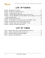
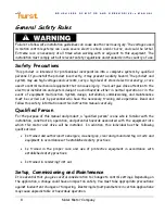
General Safety Rules 


Failure to follow safe installation guidelines can cause death or serious injury. The voltages used 
in motion control systems can cause severe electric shock and/or burns, and could be lethal. 
Extreme care is necessary at all times when working with or adjacent to this equipment. The 
installation must comply with all relevant safety regulations and standards in the country of use. 

Safety Precautions 

This product is intended for professional incorporation into a complete system by qualified 
persons. If you install the product incorrectly, it may present a safety hazard. The product and 
system may use high voltages and currents, carry a high level of stored electrical energy, or are 
used to control mechanical equipment that can cause injury.  You must give close attention to the 
electrical installation and system design to avoid hazards either in normal operation or in the 
event of equipment malfunction. System design, installation, commissioning, and maintenance 
must be carried out by personnel who have the necessary training and experience. Read and 
follow this safety information and this instruction manual carefully. 

Qualified Person 

For the purpose of this manual and product, a “qualified person” is one who is familiar with the 
installation, construction, operation, and potential hazards associated with the equipment into 
which this motor and drive will be installed.  In addition, this individual has the following 
qualifications: 


Is trained and authorized to energize, de-energize, clear and ground and tag circuits and 
equipment in accordance with established safety practices. 


Is  trained  in  the  proper  care and use of protective equipment in accordance with 
established safety practices. 


Is trained in rendering first aid. 

Setup, Commissioning and Maintenance 

It is essential that you give careful consideration to changes to control settings. Depending on 
the application, a change could have an impact on safety. You must take appropriate precautions 
against inadvertent changes or tampering.  Restoring default parameters in certain applications 
may cause unpredictable or hazardous operation. 

Содержание GreenDrive Dynamo

Страница 1: ...amo Brushless DC Motor and GreenDriveTM Manual This manual was developed as a guide for use by FIRST Robotics Teams using Controller Part Number 840205 000 in conjunction with the Nidec Dynamo BLDC Mo...

Страница 2: ...hange the design or operation of the equipment described herein and any associated motion products without notice Part Number TDE840205 000 Revision 1 Date November 13 2017 Nidec Motor Company 2017 Re...

Страница 3: ...ana 47670 U S A Telephone 812 385 2564 It is Nidec Motor Company s goal to ensure your greatest possible satisfaction with the operation of our products We are dedicated to providing fast friendly and...

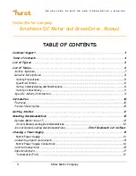
Страница 4: ...Qualified Person 8 Setup Commissioning and Maintenance 8 Safety of Machinery 9 Specific Safety Information 9 Introduction 10 Features 10 Product Description 10 Getting Started 11 Mounting Recommendati...

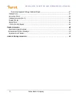
Страница 5: ...Company Externally Supplied Voltage Command Input 17 PWM Pin 3 17 Direction Pin 6 18 PWM Direction Pin 7 18 Enable Pin 8 18 GND Pin 9 19 5 Vdc Pin 10 Input 19 PWM Direction 20 Mechanical Specification...

Страница 6: ...ONTROL METHOD W O INTERNAL 5 VDC SUPPLY TYPICAL CONNECTIONS 20 FIGURE 6 DYNAMO SIZE 17 MOTOR 21 FIGURE 7 MOTOR POWER SUPPLY CABLE HURST PART NUMBER 120016 21 FIGURE 8 MOTOR POWER SUPPLY MATING CONNECT...

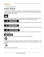
Страница 7: ...ages that follow this symbol to avoid possible injury or death DANGER indicates a hazardous situation which if not avoided will result in death or serious injury WARNING indicates a hazardous situatio...

Страница 8: ...ipment malfunction System design installation commissioning and maintenance must be carried out by personnel who have the necessary training and experience Read and follow this safety information and...

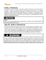
Страница 9: ...afety Information Users must determine the suitability of the control for their application including the level of reliability required and are solely responsible for the function of the end use produ...

Страница 10: ...roduct Description The Nidec brushless DC motion control system is an integrated variable speed brushless DC motor and control package This system includes a low voltage customer interface that can be...

Страница 11: ...h the internal two channel quadrature encoder or tachometer signal allows the user to close a speed loop internally to the control for applications requiring minimum speed variation with varying loadi...

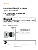
Страница 12: ...The figure below illustrates the screw thread sizes thread engagement length and torque requirements for mounting the Dynamo Size 17 motor FIGURE 1 DYNAMO SIZE 17 MOTOR At 25 C ambient the max motor...

Страница 13: ...not exceed this voltage The maximum continuous operating current handled by the GreenDriveTM is 10 amps Where the maximum motor current is less than 10A the power supply rating should be based on the...

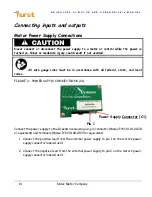
Страница 14: ...es must be in accordance with all federal state and local codes FIGURE 2 POWER SUPPLY CONNECTIONS C1 Connect the power supply to the GreenDriveTM using a 2 pin connector Molex P N 39 01 2020 or equiva...

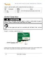
Страница 15: ...nections Never connect or disconnect the power supply to a motor or control while the power is turned on Minor or moderate injury could result if not avoided All wire gauge sizes must be in accordance...

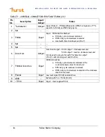
Страница 16: ...command Used with Direction Input pin Pin 7 4 NA 5 NA 6 Direction Output Direction Output 0 Vdc output clockwise lead end 5 Vdc output counter clockwise lead end Can be used in conjunction with Tachom...

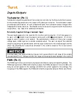
Страница 17: ...potentiometer If a 4 Vdc supply is used a resistor is not needed The potentiometer consists of three pins a supply voltage input a GND input and a variable command output The user can adjust the comma...

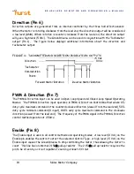
Страница 18: ...d Operating Modes The PWM Direction input operates in PWM Direction Control Method where 0 duty cycle maximum command in the counterclockwise direction viewed from the lead end 50 duty cycle minimum c...

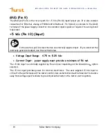
Страница 19: ...n this section pin 10 is described as an externally supplied input If you selected the internally generated output see the section below Voltage Input Range 4 75 to 5 25 Vdc Current Input power supply...

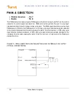
Страница 20: ...tion with change in duty cycle input The PWM signal should be an active high PWM signal at 25 kHz to the PWM input pin A 0 duty cycle input indicates maximum command in the counterclockwise direction...

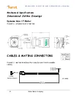
Страница 21: ...y Mechanical Specifications Dimensional Outline Drawings Dynamo Size 17 Motor FIGURE 6 DYNAMO SIZE 17 MOTOR CABLES MATING CONNECTORS FIGURE 7 MOTOR POWER SUPPLY CABLE HURST PART NUMBER 120016 24 5 610...

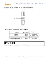
Страница 22: ...POWER SUPPLY MATING CONNECTOR C1 TABLE 3 MOTOR POWER SUPPLY CABLE REFERENCE Description Manufacturer Manufacturer Part Connector Molex 39 01 2020 Terminal Molex 39 00 0038 chain Molex 39 00 0039 loos...

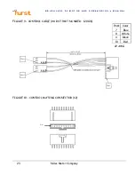
Страница 23: ...D C M O T O R A N D G R E E N D R I V E T M M A N U A L 23 Nidec Motor Company FIGURE 9 CONTROL CABLE HURST PART NUMBER 120106 FIGURE 10 CONTROL MATING CONNECTOR C2 Pin Color 7 Blue 8 White 9 Black 10...

Страница 24: ...CABLE REFERENCE Description Manufacturer Manufacturer Part Connector Molex 50 57 9410 Terminal Molex 16 02 0087 chain Molex 16 02 0103 loose Connector TE Connectivity 87499 6 Terminal TE Connectivity...

Отзывы: