B R U S H L E S S D C M O T O R A N D G R E E N D R I V E
T M
M A N U A L
20
Nidec Motor Company
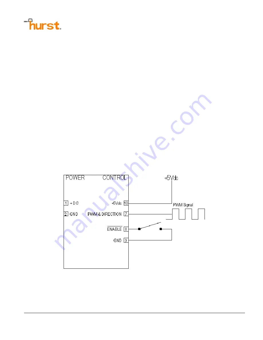
PWM & DIRECTION
PWM & Direction - Pin 7
Enable
– Pin 8
The PWM & Direction mode accepts a PWM signal on the Direction input pin (Pin 7) on the control
connector to control speed and direction. PWM & Direction permits the user to vary input
command and direction with change in duty cycle input. The PWM signal should be an active high
PWM signal at 25 kHz to the PWM input pin. A 0% duty cycle input indicates maximum command
in the counterclockwise direction when viewing the motor from the lead end. A 50% duty cycle
input indicates minimum command. A 100% duty cycle input indicates maximum command in the
clockwise direction when viewing the motor from the lead end. A high level on the Enable pin
enables the drive.
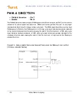
FIGURE 5 – PWM & DIRECTION CONTROL METHOD W/O INTERNAL 5 VDC SUPPLY
(TYPICAL CONNECTIONS)

