68
Commander S100 User Guide
P2.04
Stopping Mode Selector
Range:
0 to 5
Default:
1 (Ramp)
Defines how the motor is controlled when the run signal is removed from the drive.
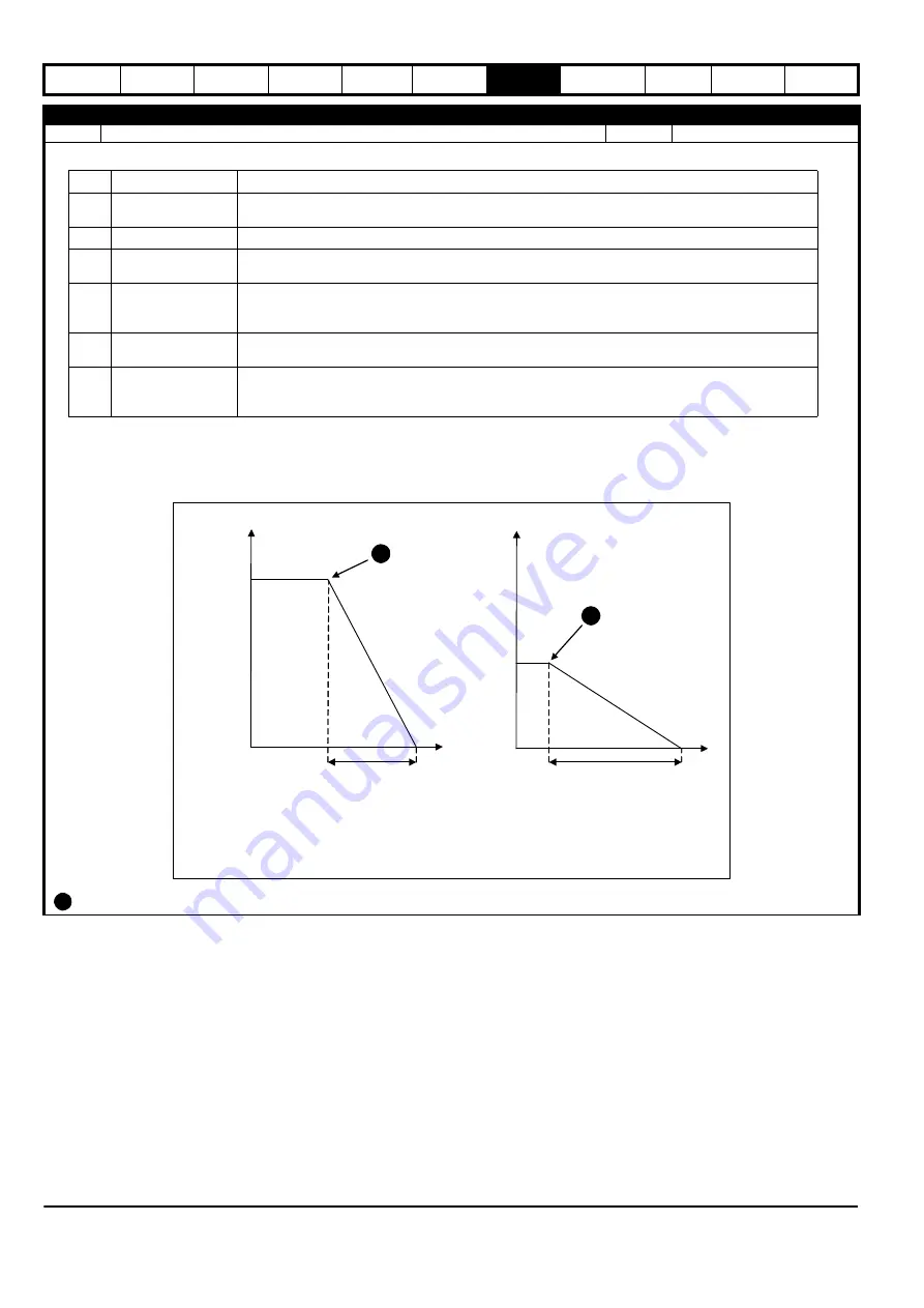
Distance Stop Example:
Figure 7-3 Distance Stop
is the point that the ‘Run’ signal is removed.
Value Stopping Mode
Description
0
Coast
Remove power from the motor and allow to spin under control of the load. The drive waits for 1 second
before it can be restarted.
1
Ramp
Motor slows down to 0 Hz under control of the drive.
2
Ramp & DC Brake
Ramp stop to 0 Hz followed by DC injection at a level defined by
DC Braking Current Level
(P3.13) for a
time defined by
DC Braking Time
(P3.14). This can prevent the motor from moving after the deceleration.
3
DC Brake, 0 Hz detect
Low frequency current injection with detection of low speed and then DC injection at a level defined by
DC
Braking Current Level
(P3.13) for a time defined by
DC Braking Time
(P3.14). The drive waits for 1
second before it can be restarted.
4
Timed DC Brake
DC injected at a level defined by
DC Braking Current Level
(P3.13) for a time defined by
DC Braking Time
(P3.14). The drive waits for 1 second before it can be restarted.
5
Distance
Stops in the same distance from any speed as it would at the specified deceleration rate from the
maximum frequency. See figure 7-2 below. Distance stop will not function if S-ramp has been enabled
(P2.05 > 0)
T
Frequency (Hz)
Distance (5)
P2.02
0
Time (s)
T = Deceleration Rate 1 (P2.07)
2 x T
Frequency (Hz)
P2.02 x 0.5
0
A
A
A
Содержание COMMANDER S100
Страница 118: ...0478 0650 02...


