Rev. 1 - 05/10/2021
OPERATING MANUAL
OPERATING MANUAL
EN
EN
39/56
12. SAFE OPERATING AREA LIMITATIONS
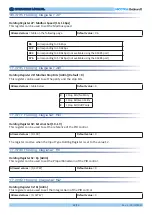
The speed limits can be adjusted for the signal rescaling, but also to limit the noise in the final application.
The
Input Register 2 indicates the Speed Reference (minimum speed during alignment and dragging and the
Set Speed in Closed Control Loop). The
Input Register 3 indicates the Measured Speed.
12.1 Speed limitation
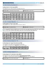
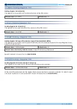
The driver is set by factory default to the max achievable electrical input power to the driver depending on
the model. During the functioning it is possible to monitor the power absorption by reading the
Input Register
31. If for some application it is necessary to keep the absorption of the fan below a defined power value, it is
possible to reduce the max power out by modifying the
Holding Register 36.
12.2 Power limitation
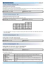
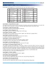
The drivers are set by factory default to the max peak current out that changes depending on the motor
windings characteristics.
During the functioning it is possible to read the peak current to the motor by reading the
Input Register 12.
It is possible to reduce the motor current by modifying the
Holding Register 7. It is suggested to keep the
motor current above 3500mA.
12.3 Output current limitation
This feature is not available for RDPs.
12.4 Input current limitation
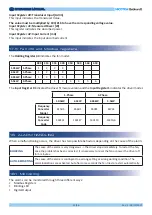
In case of completely locked rotor, the current injected could damage the motor if it lasts for long and if the
alarm is repeated indefinitely.
The Loss of Synchronism alarm is repeated for a number of times defined by the "
Num Failures Sync" Holding
Regioster 57 (not changeable by users).
Once the max trials are reached, the alarm becomes blocking.
If the fan can restart and can run for one minute before the max number is reached, the counter is reset.
For further information about the Loss of Synchronism, see paragraph 18.2.
11.10 Locked rotor (for 5.5 kW drivers only)


