background image

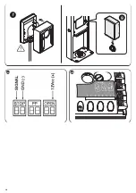
VIII

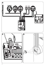
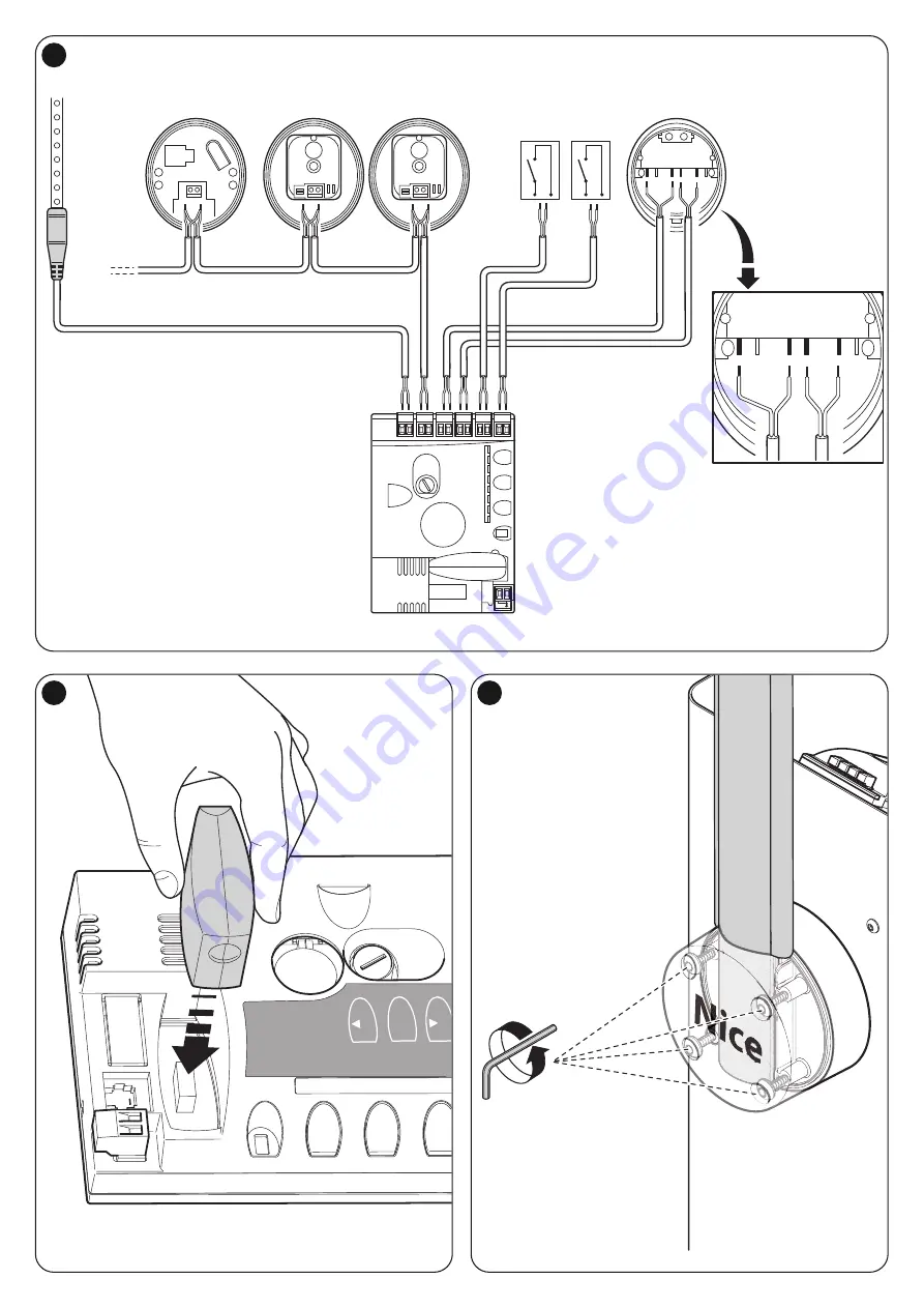
FLASH

MOTB/MOFB

OPEN CLOSE

TX

RX

BLUEBUS STOP

OPEN

CLOSE

P.P.

NC

NC

NO

NO

CC

27

Open

Sto

p

Se

t

Close

Fuse 1AT

L2

L3

L4

L5

L6

L7

L8

28

29

Содержание S-BAR

Страница 1: ...so FR Instructions et avertissements pour l installation et l utilisation ES Instrucciones y advertencias para la instalación y el uso DE Installierungs und Gebrauchsanleitungen und Hinweise PL Instrukcje i ostrzeżenia do instalacji i użytkowania NL Aanwijzingen en aanbevelingen voor installatie en gebruik Automatic barrier ...

Страница 2: ...s of overvoltage category III All product installation and maintenance operations must be performed with the automation disconnected from the power mains If the power disconnect device is not visible from the location of the automation before starting work ing a suitable notice must be affixed on the power disconnect device stating WARNING MAINTENANCE IN PROGRESS Connect the product to an electric...

Страница 3: ...the immedi ate vicinity Release of hazardous substances The product does not contain and or release hazardous substances in con formity with the provisions of the standard EN 13241 1 point 4 2 9 and ac cording to the list of substances stated in the web site of the European Com munity http europa eu int comm enterprise construction internal dangsub dangmain_en htm Last update 17 03 2003 Special wa...

Страница 4: ...ith the intended use Ensure that all limits conditions and warnings in this manual can be observed 3 2 1 Product durability The lifetime is the average economic duration of the product The value of life time is strongly influenced by the intensity of the manoeuvres i e the sum of all factors that contribute to product wear see Table 2 To estimate the lifetime of your automation proceed as follows ...

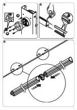
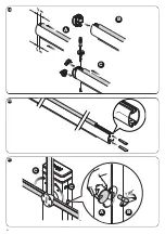
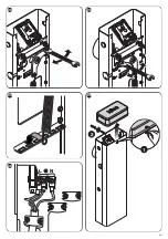
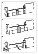
Страница 5: ...e assembly 01 Lightly grease the aluminium guide on both sides fig 17 02 Perform this operation on both ends of the pole insert the first part of impact protection rubber in the slot through to the end of the pole then insert the joint for the impact protection rubber fig 18 and repeat with all parts 03 Position the pole plug fig 19 A the impact protection must be inserted by at least 1 cm B inser...

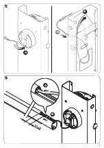
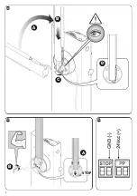
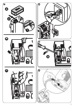
Страница 6: ...h the unit dis connected from the mains power supply 01 Loosen the screws of the cover fig 25 02 Route the electric cables inside SBAR starting from the base towards the control unit and routing them to the left 03 Connect the wires of the electric power cable to the 3 contact terminal with fuse and secure the cable with the collar fig 26 04 Connect the other cables as shown in the wiring diagram ...

Страница 7: ...XBA8 optional accessories On the cover of the barrier a LED flashing light mod XBA8 may be fitted The operating mode of this flashing light may be modified through the Oview pro grammer or with suitable programmes of the control unit For further informa tion refer to the instruction manual for the product 4 10 Connection of other devices SBAR also enables power supply to external devices a radio r...

Страница 8: ...tation see standard EN 12445 com bined with device types D presence detectors e g photocells Bearing in mind that this type of use is among the most intensive the same testing sequence can be effectively implemented in less intensive conditions 1 Ensure that all specifications in this manual have been observed with spe cial reference to the chapter 1 Safety Instructions 2 Check correct balancing o...

Страница 9: ... When this function is set to ON the level of control unit sensitivity in obstacle detection can be increased considerably If used as a means to read the impact force of the motor the values speed and motor force must be set accordingly in the level 2 menu L8 Direction of motor rotation This parameter enables inversion of the direction of motor rotation to enable barrier installation on the right ...

Страница 10: ...as sociated with the input or the radio control Step by step Function Step by step L3 L1 L2 L3 L4 L5 L6 L7 L8 Speed 1 30 slow Speed 2 47 Speed 3 65 Speed 4 82 Speed 5 100 fast Open V3 Close V2 Open V4 Close V3 Open V5 Close V4 Sets the motor speed during normal travel Speed Motor L4 L1 L2 L3 L4 L5 L6 L7 L8 Pole Open Indicator Function 24 V 10 W Active if pole closed 24 V 10 W Active if pole open 2...

Страница 11: ...ciated with the Step Step input and enables an always open command when the Step Step command remains active for more than 3 seconds This function is valid for any setting of the Step Step input see SS Function in Table 7 For example it can be used to connect a clock for programming permanent opening of the barrier during a specific time band Move anyway function If one or more safety devices malf...

Страница 12: ...1 Press and hold down the Set key for approx 3 seconds 02 Release the key when LED L1 starts flashing 03 Press keys or to move from the flashing LED to L7 LED input LED for the Maintenance Notification parameter 04 Press and hold the Set key through to completion of point 07 05 Wait approx 3 seconds until the LED representing the current level of the Maintenance Notification illuminates 06 Press a...

Страница 13: ... 3 3 MOTB digital selector and proximity reader for MOMB transponder cards The Bluebus system enables connection of up to 4 MOTB digital selectors or 4 MOMB transponder badge readers MOTB enables control of the automation by entering one of the memorised numerical codes on the keypad MOMB enables control of the automation by simply placing the memorised transponder bade close to the automation The...

Страница 14: ...tion indicates Stand BY not active On During normal operation indicates Stand BY active Flashes Programming of functions in progress If this flashes together with L3 this indicates that the pole opening and closing learning phase must be performed see paragraph 4 5 Led 5 Description Off During normal operation indicates Short deceleration active On During normal operation indicates Long decelerati...

Страница 15: ...e 2 flashes Photocell activated At the start of the manoeuvre one or more photocells do not ena ble it check to see if there are any obstacles 3 flashes second pause 3 flashes Activation of Motor Force limiter During the movement the pole has experienced excessive fric tion identify the cause 6 flashes second pause 6 flashes Maximum limit of manoeuvres per hour exceeded Wait a few minutes until th...

Страница 16: ...h XBA4 accesory cycles hour at nominal torque Maximum continuous operating 10 8 with XBA4 accesory minutes time at nominal torque Opening time 4 s 5s with XBA4 accesory Durability between 80 000 and 500 000 manoeuvre cycles according to the conditions stated in Table 2 Peak power supply 230 Vac 50 60Hz Peak power absorption on start up 300W Maximum power at nominal torque 200 W Insulation class I ...

Страница 17: ...lation of this document to the declaration Directive 89 106 EEC of the European Council of 21 December 1988 regarding the approximation of legislation regulations and administration of Member States concerning construction products according to the following harmonised standards EN 13241 1 2003 The product also complies with the following standards EN 60335 1 2002 A1 2004 A11 2004 A12 2006 A2 2006...

Страница 18: ...i e the pole will continue to move while the command is activated THE POLE STOPS AS SOON AS THE COMMAND IS RELEASED If the safety devices are out of service the automation must be repaired as soon as possible 5 Even if you possess the skills never modify the system or pro gramming and setting parameters of the automation this is the responsibility of the installer 6 Testing periodic maintenance an...

Страница 19: ... a safe place for future inspections by authorised organisations This Maintenance Register refers to the following automation mod SBAR Serial n Date of installation at The following enclosed documents are part of the Register 1 Maintenance schedule 2 3 4 5 6 According to the enclosed document Maintenance Schedule maintenance operations must be performed at the following intervals every 6 months or...

Страница 20: ...glish Date Description of operation describe checks adjustments repairs modifications etc Signature of technician Signature of owner That all phases as envisaged in the maintenance schedule have been performed ...

Страница 21: ...ines applications par exemple en excluant l utilisation unique ment pour véhicules peut le faire rentrer dans le champ d application de la Directive Produits de construction 89 106 CEE et de la norme harmonisée EN 13241 1 correspondante Dans le paragraphe 1 3 1 sont indiqués tous les critères d installation nécessaires pour que le produit satisfasse aux exigences essentielles de la directive 89 10...

Страница 22: ... signalisation adéquate et si d autres types sont demandés il y a suffisamment d espace à proximité immédiate Dégagement de substances dangereuses Le produit ne contient pas et ou ne dégage pas de substances dangereuses conformément à ce qui est prévu par la norme EN 13241 1 point 4 2 9 et selon la liste des substances présente sur le site internet de la Communauté Européenne http europa eu int co...

Страница 23: ...ndiquées dans le chapitre Caractéristiques techniques du produit et la fréquence des cycles indiqués dans le Tableau 1 sont compatibles avec l utilisation prévue Vérifier que la durabilité estimée voir paragraphe 3 2 1 est compatible avec l utilisation prévue Vérifier qu il est possible de respecter toutes les limitations les conditions et les recommandations indiquées dans le présent manuel 3 2 1...

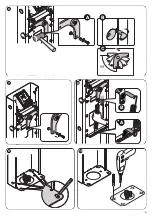
Страница 24: ...dre la prise complète du ciment en général au moins 2 semaines 05 Retirer les 4 écrous supérieurs des agrafes 06 Ouvrir le fût de la barrière fig 4 07 Positionner correctement la barrière et la bloquer avec les écrous et ron delles fournis avec la plaque de fondation et enlevés au point 04 fig 13 A B 3 5 Installation de la lisse 3 5 1 Assemblage du support pour la lisse 01 Introduire les 2 chevill...

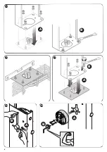
Страница 25: ...re la tension du ressort ou vers l extérieur pour augmenter la tension du ressort 05 Bloquer l opérateur voir paragraphe 3 6 ATTENTION Toutes les connexions doivent être effectuées en l ab sence d alimentation électrique de secteur 01 Dévisser les vis du couvercle fig 25 02 Faire passer les câbles électriques à l intérieur de SBAR en partant de la base vers la logique de commande et en les orienta...

Страница 26: ...quer le connecteur à l intérieur de la fente de la lisse fig 32 D 10 Introduire la lisse et la bloquer avec son couvercle en vissant avec force les 4 vis et en faisant attention à ne pas pincer le câble de câblage fig 33 4 9 Branchement du clignoteur à led mod XBA7 ou sémaphore à leds mod XBA8 accessoires optionnels Sur le couvercle de la barre on peut y appliquer un clignoteur à led mod XBA7 La m...

Страница 27: ...contrôle des automatismes de portails et barrières levantes Toutes ces activi tés doivent être effectuées sous le contrôle direct de l installateur responsable c est à dire celui qui mettra son nom et sa signature dans le cadre N 1 de la déclaration de conformité voir annexe I Les dispositifs supplémentaires ou en option doivent être soumis à un essai spécifique aussi bien en ce qui concerne leur ...

Страница 28: ...ec lequel la logique détecte la présence d un obstacle Si elle est utilisée comme soutien pour la détection de la force d impact du moteur il faut aussi régler les paramètres vitesse et force moteur dans le menu de deuxième niveau L8 Sens de rotation moteur Ce paramètre permet d inverser le sens de rotation du moteur pour pouvoir installer la barrière à droite la valeur configurée à l usine est OF...

Страница 29: ...ntenue Ouverture en semi automatique fermeture avec commande par action maintenue Règle la séquence de commandes associées à l entrée ou bien à la com mande radio Pas à pas Fonction Pas à pas L3 L1 L2 L3 L4 L5 L6 L7 L8 Vitesse 1 30 lente Vitesse 2 47 Vitesse 3 65 Vitesse 4 82 Vitesse 5 100 rapide Ouvre V3 ferme V2 Ouvre V4 ferme V3 Ouvre V5 ferme V4 Règle la vitesse du moteur durant la course norm...

Страница 30: ...ne particularité de la logique de commande elle est asso ciée à l entrée Pas à pas et permet de commander toujours une manœuvre d ouverture quand la commande de Pas à pas reste active pendant plus de 3 secondes Cette fonction est valable pour n importe quelle programmation de l entrée Pas à pas voir Fonction PP dans le Tableau 7 Par exemple elle peut être utilisée pour connecter une horloge pour p...

Страница 31: ...nomalies procéder suivant les indications du Tableau 12 TABLEAU 11 01 Presser et maintenir enfoncée la touche Set pendant environ 3 s 02 Relâcher la touche quand la led L1 commence à clignoter 03 Presser la touche ou pour se déplacer de la led en train de clignoter à la led L7 led d entrée Avis de maintenance 04 Presser et maintenir enfoncée la touche Set jusqu à la fin du point 07 05 Attendre env...

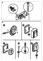
Страница 32: ...pour les photocellules dans la boîte d accessoires fig 43 b 03 Encastrer la carte sur le fond du boîtier fig 43 c 04 Percer le caoutchouc prévu pour le passage du câble électrique fig 43 d 05 Faire passer le cordon d alimentation et le brancher sur le bornier de la photocellule fig 43 e 06 Fermer le fond de le boîtier avec le couvercle en ayant pris soin de bloquer le caoutchouc dans son siège fig...

Страница 33: ...phe 4 4 Led 2 Description Éteinte Durant le fonctionnement normal elle indique que la fonction Refermeture après passage devant photocellule n est pas active Allumée Durant le fonctionnement normal elle indique que la fonction Refermeture après passage devant la photocellule est active Clignote Programmation des fonctions en cours Si elle clignote en même temps que L1 cela signifie qu il faut effe...

Страница 34: ...econnaissance des dispositifs voir paragraphe 4 5 2 clignotements pause de 1 seconde 2 clignotements Intervention d une photocellule Au début de la manœuvre une ou plusieurs photocellules nient l autorisation à la manœuvre vérifier si elles sont occultées par un obstacle 3 clignotements pause de 1 seconde 3 clignotements Intervention du limiteur de la Force moteur Durant le mouvement la lisse a su...

Страница 35: ...BA4 cycles heure au couple nominal Temps maximum de fonctionnement 10 8 avec accessoire XBA4 minutes continu au couple nominal Temps d ouverture 4 s 5s avec accessoire XBA4 Durabilité Estimée entre 80 000 cycles et 500 000 cycles de manœuvres suivant les conditions indiquées dans le Tableau 2 Alimentation de crête 230 Vac 50 60Hz Puissance de crête absorbée au démarrage 300 W Puissance maximum au ...

Страница 36: ...ective 89 106 CEE du Conseil du 21 Décembre 1988 relative à l harmonisation des dispositions législatives réglementaires et administratives des États membres concernant les produits de construction selon les normes harmonisées suivantes EN 13241 1 2003 En outre le produit s avère conforme aux normes suivantes EN 60335 1 2002 A1 2004 A11 2004 A12 2006 A2 2006 A13 2008 Le produit s avère conforme li...

Страница 37: ...st maintenue la lisse continue sa manœuvre DÈS QUE LA COMMANDE EST RELÂCHÉE LA LISSE S ARRÊTE Avec les dispositifs de sécurité hors service il faut faire réparer au plus tôt l automatisme 5 Même si vous estimez en être capable ne modifiez pas l installa tion et les paramètres de programmation et de réglage de l automa tisme la responsabilité en incombe à l installateur 6 L essai de fonctionnement ...

Страница 38: ...s inspections de la part d organismes autorisés Le présent Registre de maintenance se réfère à l automatisme suivant mod SBAR n de série installé en date du lieu d installation Le Registre de maintenance inclut les documents suivants 1 Plan de maintenance 2 3 4 5 6 Sur la base du document joint Plan de Maintenance les opérations de maintenance doivent être effectuées en respectant la fréquence sui...

Страница 39: ... l automatisme 11 Vérification du système de sectionnement de l alimentation électrique en agissant sur le dispositif de sectionnement de l ali mentation et en déconnectant les éventuelles batteries tampon vérifier que toutes les leds présentes sur la logique de commande sont éteintes et que la lisse ne bouge pas quand on envoie une commande Vérifier l efficacité du système de blocage pour éviter ...

Страница 40: ...en Anwendungsbereich der Richtlinie Bauprodukte 89 106 EWG und der diesbezüglichen Norm EN 13241 1 fallen Im Abschnitt 1 3 1 sind alle notwendigen Installationskriterien angegeben damit das Produkt den grundsätzlichen Eigenschaften der Richtlinie 89 106 EWG entspricht wer die Installation ausführt kann prüfen und sicherstellen ob all diese Kriterien streng eingehalten wurden Die grundsätzlichen An...

Страница 41: ...urchquerung kann als ausschließlich für Fahrzeu ge betrachtet werden wenn für die anderen Arten zum Beispiel Fußgänger ein ausdrückliches Verbot vorliegt zum Beispiel über korrekte Hinweisschilder und wenn andere Arten nicht gefordert werden ausreichend Platz in der direk ten Nähe ist Abgabe gefährlicher Substanzen Das Produkt enthält und oder gibt keine gefährlichen Substanzen ab wie durch Norm E...

Страница 42: ...gebracht werden kann 3 2 Einsatzgrenzen des Produkts Vor der Installation des Produkts muss geprüft werden ob alle Werten die im Kapitel Technische Produkteigenschaften aufgeführt sind und die max Häu figkeit der Zyklen der Tabelle 1 mit der vorgesehenen Nutzung übereinstimmen Prüfen ob die geschätzte Dauer siehe Abschnitt 3 2 1 mit dem vorgesehe nen Zweck kompatibel ist Prüfen ob es möglich ist a...

Страница 43: ...mführung auf beiden Seiten leicht ölen Abb 17 02 Dies auf beiden Schrankenbaumseiten ausführen Das erste Stoßschutz gummiteil in den Schlitz stecken und bis zum Ende des Schrankenbaums schieben dann die Gelenkverbindung für Stoßschutzgummis einfügen Abb 18 und bei den anderen Teilen wiederholen 03 Den Verschluss des Schrankenbaums positionieren Abb 19 A Der Stoßschutz muss mindestens 1 cm im Schra...

Страница 44: ... um die Spannung der Feder zu erhöhen 05 Den Antrieb entriegeln siehe Abschnitt 3 6 ACHTUNG Alle elektrischen Anschlüsse sind ohne Stromspeisung aus zuführen 01 Die Deckelschrauben abschrauben Abb 25 02 Die Stromkabel innerhalb von SBAR verlaufen lassen wobei man von der Basis zur Steuerung hin ausgeht und sie auf die linke Seite dieser ausrichtet 03 Die Drähte des Stromkabels an die 3 Kontakt Kle...

Страница 45: ...ie 4 Schrauben kräftig anziehen und darauf achten das Kabel der Verkabelung nicht ein zuquetschen Abb 33 4 9 Anschluss Blinker an Leuchtdiode Mod XBA7 oder Ampel an Leuchtdiode Mod XBA8 Zusatzzubehör Auf der Abdeckung des Schrankenhebers kann eun Blinker mit Leuchtdiode Mod XBA7 eingesetzt werden Die Betriebsart dieses Blinkers kann mit dem Programmator Oview geändert oder mit dem Steuergerät ents...

Страница 46: ...ne Unterschrift in das Feld Nr 1 der Konformitätserklä rung einträgt siehe Anlage I Die zusätzlichen oder hinzugefügten Vorrichtungen müssen einer spezifischen Abnahme unterzogen werden was ihre Funktionstüchtigkeit und ihre korrekte Verbindung mit SBAR angeht 5 1 Abnahme Die für die Abnahme auszuführende Vorgehensweise bezieht sich auf eine typi sche Anlage Abb 1 mit einer Anwendungsweise nicht a...

Страница 47: ...unktion ist es möglich das Empfindlichkeitsniveau bemerkenswert zu erhöhen mit dem die Steuerung die Anwesenheit eines Hindernisses erfasst Falls als Hilfe zur Aufprallkraftmessung des Motors benutzt sind auch die Parameter Geschwindigkeit und Motorkraft im Menü des zweiten Niveaus einzustellen L8 Motorendrehrichtung Dieser Parameter ermöglicht die Umkehrung der Drehrichtung des Motors um die Schr...

Страница 48: ...usführung der ersten beiden Bewegungen erfasst Kraft Motor in Schließung L7 L1 L2 L3 L4 L5 L6 L7 L8 2500 5000 10000 15000 20000 30000 40000 50000 Wenn der Ausgang FLASH als War tungsmeldeleuchte programmiert wird Regelt die Höchstzahl der auszufü hrenden Bewegungen wonach ange zeigt wird dass die Wartung der Automatisierung ausgeführt werden muss Wartun gshinweis TABELLE 7 Funktionen zweites Nivea...

Страница 49: ...ttbetrieb verbunden und ermöglicht immer eine Öffnungsbewegung zu steuern wenn die Schrittbetriebsteuerung länger als 3 Sekunden aktiv bleibt Diese Funktion gilt für jede Programmierung des Eingangs PP Schrittbetrieb siehe die Funktion Schrittbetrieb in Tabelle 7 Sie kann zum Beispiel für den Anschluss einer Uhr verwendet werden um die permanente Öffnung der Schranke in einer bestimmten Zeitspanne...

Страница 50: ...tleiste Um die Liste der Störungen zu überprüfen wie in Tabella 12 beschrieben vorgehen TABELLE 11 01 Mindestens 3 Sekunden lang auf die Taste Set drücken und gedrückt halten 02 Die Taste loslassen wenn die LED L1 zu blinken beginnt 03 Auf die Tasten oder drücken um von der Led zu gehen die bei LED L7 blinkt Eingangsled Wartungsmeldung 04 Die Taste Set drücken und gedrückt halten bis Punkt 07 abge...

Страница 51: ...Elektrokomponenten beschädigen 02 Die für die Fotozelle vorgesehene und auf dem Zubehörkasten befindliche Box öffnen Abb 43 b 03 Die Karte am Boden der Box einrasten Abb 43 c 04 Den für die Passage des Stromkabels vorgesehenen Gummi durchbohren Abb 43 d 05 Das Kabel durchschieben und an der Klemme der Fotozelle anschließen Abb 43 e 06 Den Boden der Box mit der Abdeckung verschließe darauf achten d...

Страница 52: ...ungs und Schließbewegung siehe Abschnitt 4 5 Led 4 Beschreibung Aus Zeigt beim Normalbetrieb an Standby deaktiviert Ein Zeigt beim Normalbetrieb an Standby aktiviert Blinkt Programmierung der Funktionen im Gang Falls sie zusammen mit L3 blinkt muss die Erlernung der Positionen Öffnung und Schließung der Schranke ausgeführt werden siehe Abschnitt 4 5 Led 5 Beschreibung Aus Zeigt beim Normalbetrieb ...

Страница 53: ...eführt werden siehe Abschnitt 4 5 2 Mal Blinken 1 Sekunde Pause 2 Mal Blinken Auslösung einer Lichtschranke Bei Bewegungsbeginn wird die Zustimmung zur Bewegung von einer oder mehreren Lichtschranken nicht gegeben prüfen ob Hindernisse vorhanden sind 3 Mal Blinken 1 Sekunde Pause 3 Mal Blinken Auslösung des Motorkraft Begrenzers Während der Bewegung war mehr Reibung an der Schranke vor handen Ursa...

Страница 54: ...nuten bei Nenndrehmoment Öffnungszeit 4 s 5s mit Zubehörteil XBA4 Lebensdauer zwischen ca 80 000 und 500 000 Zyklen je nach den in Tabelle 2 angegebenen Bedingungen geschätzt Spitzenspeisung 230 Vac 50 60Hz Beim Anlauf aufgenommene 300W Spitzenleistung Höchstleistung bei 200 W Nenndrehmoment Isolationsklasse I Notversorgung Ja mit Zubehörteil PS124 Zusätzliche Beleuchtung Mit Zubehör Blinker mit L...

Страница 55: ...örige Übersetzung zuzufügen Richtlinie 89 106 EWG des Rats vom 21 Dezember 1988 hinsichtlich der Annäherung der gesetzlichen regelnden und verwaltungstechnischen Anordnun gen der Mitgliedstaaten hinsichtlich der Bauprodukte gemäß den folgenden harmonisierten Normen EN 13241 1 2003 Außerdem entspricht das Produkt folgenden Normen EN 60335 1 2002 A1 2004 A11 2004 A12 2006 A2 2006 A13 2008 Das Produk...

Страница 56: ...d betätigt gehalten die Schranke bewegt sich weiter SOBALD DIE STEUERUNG FREIGE GEBEN WIRD HÄLT DIE SCHRANKE AN Wenn die Sicherheitsvorrichtungen außer Betrieb sind muss der Automatismus so schnell wie möglich repariert werden 5 Auch wenn Sie meinen dass Sie wissen wie das gemacht wird ändern Sie die Anlage und die programmierten Parameter sowie die Einstellungen der Automatisierung nicht diese Ve...

Страница 57: ...ngsregister bezieht sich auf den folgenden Automatismus mod SBAR Seriennr installiert am Adresse Teil dieses Wartungsregisters sind die folgenden anliegenden Dokumente 1 Wartungsprogramm 2 3 4 5 6 Gemäß dem anliegenden Dokument Wartungsprogramm müssen die Wartungsarbeiten mit der folgenden periodischen Häufigkeit ausgeführt werden alle 6 Monate oder zu jeweils 10 der vorgesehenen Dauer der Bewegun...

Страница 58: ...ranke und 1 m ab der Dreh achse gemessen Schließlich prüfen ob der Schlüssel für die manuelle Entriegelung an der Automatisierung zur Verfügung steht 11 Prüfung des Versorgungsabtrennungssystems Durch Einwir kung auf die Abtrennvorrichtung der Speisung und Trennung even tueller Pufferbatterien muss geprüft werden dass alle Leds in der Steuerung ausgeschaltet sind und die Schranke bei Übersendung e...

Страница 59: ... de betreffende geharmoniseerde norm EN 13241 1 laten vallen In paragraaf 1 3 1 zijn alle installatiecriteria beschreven waaraan voldaan moet worden opdat het product voldoet aan de fundamentele vereisten van de richtlijn 89 106 EEG degene die de installatie uitvoert dient zich ervan te verzekeren dat al deze criteria strikt in acht zijn genomen Indien SBAR geïnstalleerd en gebruikt wordt zonder d...

Страница 60: ...eer bijvoorbeeld voetgangers er een uitdrukkelijk verbod geldt dat bijvoorbeeld door speciale borden wordt aangegeven en als er voor eventuele andere soorten verkeer hiervoor in de onmiddellijke nabijheid van de barrière een adequate ruimte voor is Uitstoot van gevaarlijke stoffen Het product bevat geen en of stoot geen gevaarlijke stoffen uit in overeenstem ming met de voorschriften van de norm E...

Страница 61: ... sluitmanoeuvres kunnen belemmeren Controleer of elk van de te installeren inrichtingen wordt opgesteld op een beschutte plek beschermd tegen stoten 3 2 Gebruikslimieten van het product Controleer alvorens tot installatie van het product over te gaan of alle in het hoofdstuk Technische gegevens van het product vermelde waarden en de in Tabel 1 vermelde maximumfrequentie van de cycli compatibel zij...

Страница 62: ...an beide zijde licht in met olie afb 17 Voer dit punt voor beide zijden van de slagboom uit installeer het eer ste stuk stootrubber in de sleuf en duw het tot aan het einde van de slag boom installeer vervolgens het verbindingsstuk voor het stootrubber afb 18 en doe hetzelfde met de andere stukken 03 Plaats de dop van de slagboom afb 19 A het stootrubber moet ten minste 1 cm naar binnen steken B i...

Страница 63: ...r de buitenkant om de veerspanning te vergroten 05 Vergrendel de reductiemotor zie paragraaf 3 6 LET OP Bij het uitvoeren van elektrische aansluitingen mag de installa tie absoluut niet onder netspanning staan 01 Draai de schroeven van het deksel los afb 25 02 Voer de elektriciteitskabels de SBAR binnen vanaf de basis naar de bestu ringseenheid toe en leid ze naar de linkerkant van de besturingsce...

Страница 64: ...heid zie schema van afb 27 09 Positioneer en blokkeer de connector in de sleuf van de slagboom afb 32 D 10 Installeer de slagboom en blokkeer hem met het deksel door de 4 schroe ven met kracht vast te draaien waarbij u er op let de kabel niet af te klem men afb 33 4 9 Aansluiting LED knipperlicht mod XBA7 of LED stoplicht mod XBA8 optionele accessoires Op de deksel van de slagboombarrière kan een ...

Страница 65: ... controle van automatiseringen voor poorten en wegbarrières bepaalt in acht genomen zijn Al deze activiteiten dienen te worden verricht onder direct toezicht van de verantwoordelijke installateur d w z degene die zijn naam en handtekening in het kader nr 1 van de verklaring van overeenstemming zet zie bijlage I De aanvullende of optionele inrichtingen moeten worden onderworpen aan een specifieke e...

Страница 66: ...sniveau waarmee de besturingseenheid de aanwezigheid van een obstakel detecteert aanzienlijk verhoogd worden Als de functie gebruikt wordt als hulp bij het detecteren van de stootkracht van de motor dienen bijgevolg de waarden van snelheid en van motorkracht te worden ingesteld in het menu van het 2e niveau L8 Draairichting motor Met deze parameter kan de draairichting van de motor worden omgekeer...

Страница 67: ...g wordt ook de gevoeligheid voor de obstakeldetectie geregeld Opmerking De kracht wordt auto matisch geregistreerd gedurende het uitvoeren van de eerste twee mano euvres Kracht motor In sluitma noeuvre L7 L1 L2 L3 L4 L5 L6 L7 L8 2500 5000 10000 15000 20000 30000 40000 50000 Wanneer de uitgang FLASH gepro grammeerd is als onderhoudsverklik ker regelt het maximumaantal manoeuvres dat moet worden uit...

Страница 68: ...pen altijd Deze functie is specifiek voor de besturingseenheid hij is gekoppeld aan de ingang Stap voor stap en maakt het mogelijk altijd een openingsmanoeuvre aan te sturen wanneer de instructie Stap voor stap langer dan 3 seconden actief blijft Deze functie is geldig voor iedere willekeurige programmering van de ingang Stap voor stap zie Functie PP in de Tabel 7 De functie kan bijvoorbeeld gebru...

Страница 69: ...nden 06 Druk de toetsen en in en houd ze minstens 5 seconden ingedrukt laat de twee toetsen vervolgens weer los In deze fase zal de betreffende niveauled een aantal maal snel knipperen om aan te geven dat het aantal manoeuvres op nul werd gezet 07 Laat de toets Set los SET SET SET SET L1 L7 of en 3 s TABEL 12 01 Houd de toets Set ongeveer 3 seconden ingedrukt 02 Laat de toets los wanneer de led L1...

Страница 70: ... Open de voor de zonnecellen bestemde box die in de accessoiredoos te vinden is afb 43 b 03 Zet de kaart vast op de bodem van de box afb 43 c 04 Maak een gat in het rubber voor het doorvoeren van de elektriciteitskabel afb 43 d 05 Leid de elektriciteitskabel en sluit deze aan op het klemmetje van de zonne cel afb 43 e 06 Sluit de bodem van de box met de deksel af en zorg er daarbij voor dat het ru...

Страница 71: ...voerd Led 4 Beschrijving Uit Bij de normale functionering geeft dit aan dat Stand By niet actief is Aan Bij de normale functionering geeft dit aan dat Stand By actief is Knippert Programmering van de functies gaande Als hij tegelijk met L3 knippert betekent dit dat de procedure voor zelflering van de openings en sluitposities van de slagboom moet worden uitgevoerd zie paragraaf 4 5 Led 5 Beschrijv...

Страница 72: ...de inrichtingen te worden herhaald zie paragraaf 4 5 2 knipperingen pauze van 1 seconde 2 knipperingen Er is een fotocel in werking getreden Aan het begin van de manoeuvre geven één of meer fotocellen geen toestemming voor de beweging controleer of er obstakels aanwezig zijn 3 knipperingen pauze van 1 seconde 3 knipperingen Activering van de beperking van de Motorkracht Gedurende de beweging heeft...

Страница 73: ... Nm Nominaal koppel 25 Nm Maximale frequentie werkingscycli bij nominaal 100 80 met accessoire XBA4 cycli uur koppel Maximumduur continue werking 10 8 met accessoire XBA4 minuten bij het nominale koppel Tijd opening 4 s 5s met accessoire XBA4 Duur Geschat tussen 80 000 en 500 000 manoeuvreercycli volgens de condities die vermeld zijn in Tabel 2 Piekvoeding 230 Vac 50 60Hz Opgenomen piekvermogen 30...

Страница 74: ...e verklaring een vertaling ervan te voegen Richtlijn 89 106 EEG van de Raad van 21 december 1988 met betrekking tot de onderlinge aanpassing van de wettelijke en reglementaire en administra tieve bepalingen van de Lidstaten ten aanzien van constructieproducten volgens de volgende geharmoniseerde normen EN 13241 1 2003 Bovendien voldoet het product aan de hierop volgende normen EN 60335 1 2002 A1 2...

Страница 75: ...E SLAGBOOM STOPPEN Wanneer de beveiligingen buiten gebruik zijn moet de automati sering zo snel mogelijk gerepareerd worden 5 Ook als u denkt het zelf te kunnen doen dient u toch geen wijzi gingen in de installatie en de parameters voor programmering en instelling van de automatisering aan te brengen het is uw installateur die verantwoordelijk is 6 De eindtest het periodieke onderhoud en de eventu...

Страница 76: ...sregister heeft betrekking op de volgende automatisering mod SBAR serienummer geïnstalleerd op datum bij De volgende bijgevoegde documenten maken deel uit van dit Onderhoudsregister 1 Onderhoudsplan 2 3 4 5 6 Volgens het bijgevoegde Onderhoudsplan moeten de onderhoudswerkzaamheden met de volgende tussenpozen worden uitgevoerd iedere 6 maanden of iedere 10 van de voorziene duur manoeuvreercycli wat...

Страница 77: ...nodig is voor de handmatige ontgrendeling beschikbaar is in de nabijheid van de automatisering 11 Controle van het systeem voor afkoppeling van de voeding activeer de inrichting voor afkoppeling van de voeding en koppel de eventuele bufferbatterijen af en ga na of alle led s op de bestu ringseenheid uit zijn en of de slagboom ook bij het versturen van een bedieningsinstructie stil blijft staan Con...

Страница 78: ...I 2 1 A B C B 179 5 mm 330 mm 1146 mm 826 mm 4000 mm 3 b a d e f g h c ...

Страница 79: ...II 5 A B C 1 2 4 ...

Страница 80: ...III 9 10 90 6 A C B 7 8 B A ...

Страница 81: ...IV 14 15 A B A B 11 A B 12 13 A B ...

Страница 82: ...V 16 A B 17 18 ...

Страница 83: ...VI 20 180 21 C C A B 1cm 1cm 19 A C B ...

Страница 84: ...VII 22 23 26 L N 24 1 2 25 ...

Страница 85: ...VIII FLASH MOTB MOFB OPEN CLOSE TX RX BLUEBUS STOP OPEN CLOSE P P NC NC NO NO C C 27 Op en St op Se t Cl os e Fuse 1AT L2 L3 L4 L5 L6 L7 L8 28 29 ...

Страница 86: ...IX 30 A A B STOP 31 A B ...

Страница 87: ...X 32 A B C D STOP 33 A B 34 ...

Страница 88: ...XI 35 36 L8 37 A B 2 1 L7 L8 L8 A B C Op L5 L6 L7 L8 Stop Set Close F u s e 1 A T 38 ...

Страница 89: ...XII 300 200 700 500 39 300 200 700 500 150 40 41 ...

Страница 90: ...a c d e b XIII F2 F1 42 43 ...

Страница 91: ...XIV 44 O pe n L1 L2 L3 L4 L5 L6 L7 L8 St op Se t Cl os e Fuse 1AT 45 f g ...

Страница 92: ...07 The product also complies with the following directive in accordance with the requirements for quasi machines Directive 2006 42 EC OF THE EUROPEAN PARLIAMENT AND COUNCIL of May 17 2006 regarding machines and amending directive 95 16 EC consolidated text I declare that the pertinent technical documentation has been prepared in accordance with Annex VII B to Directive 2006 42 EC and that the foll...

Страница 93: ...IST SBARR01 4865_20 10 2011 www niceforyou com Nice SpA Oderzo TV Italia info niceforyou com ...

Отзывы: