background image

GB

9

After making connections perform a general test, i.e.:

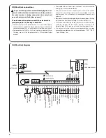
• Power the control unit and immediately check whether terminals 1-2 are mains powered and terminals 15-16 (services output) are

powered at approx. 28Vdc. If this is not the case, unplug the unit immediately and carefully check the connections and the voltage input.

• After about 2 seconds from switching on, the “OK” Led should show the control unit is working correctly by flashing regularly at 1 second

intervals.

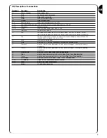
• Check that the led’s relative to the NC inputs (“Stop”, “Photo” and “Photo2”) are on (safety devices active) and that the led’s relative to the

NO inputs are off (no command present); if this is not the case, check the connections of the various devices and make sure they are in

good working order.

• Check that all the safety devices of the unit are in proper working order (emergency stop, photocells, pneumatic edges, etc.); each time

they cut in, the relative “Stop”, “Photo” or “Photo2” led’s should turn off.

• Check the motor turns in the right direction, i.e.:

release the motor and check that the release led on the board is on

move the door manually so that it is free to move during the opening and closing manoeuvres;

block the motor again and check that the release led is off

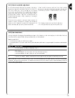
press the “Close” button (ref. K of Fig. 1) and check that the door moves in the close direction

if the opening manoeuvre is performed, press again on the close button to stop the door from moving, unplug the machine and invert

the two motor wires

regardless of the direction of movement, press the “Close” button again to stop the manoeuvre immediately

Once the connections have been successfully tested, the search for mechanical stops phase can begin.

This operation is important because the A924 control unit must measure the space covered by the motor, in terms of the number of encoder

impulses, to move the door from the maximum close position (position 0) to the maximum open position (position 1).

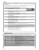
Position 0 and position 1 act as reference points for all the other positions indicated on the graph in 

Fig 4

.

POSITION 0:

is the point at which the sectional door is in the closed position, corresponding

to the mechanical stop (generally the floor).

POSITION 1:

is the point at which the sectional door is in the maximum open position, 

corresponding to the mechanical opening stops (point M).

POSITION A:

is the point at which the door is required to stop during the opening manoeuvre 

(this does not necessarily coincide with the mechanical stops in the opening cycle).

POSITION B:

is the position in which the door is required to stop during the partial opening 

manoeuvre.

POSITION RA:

is the position in which the door is required to begin slowing down during the

normal opening manoeuvre.

POSITION RC:

is the position in which the door is required to begin slowing down during the

closing manoeuvre.

The mechanical stops can be searched by means of an initial search, an automatic search or manual programming. After an “initial search”

or “automatic search”, one or more automatically detected positions can be modified by means of manual programming, if required, except

positions 0 and 1 which act as references for all the others.

3) Programming

2.7) Checking connections

The next operations involve work being done on live

circuits, some parts have mains voltage running through

them and are therefore extremely dangerous!

Pay the greatest of attention to what you are doing and

never work alone!

!

1

M

A
RA

B

RC
0

Содержание Mindy A924

Страница 1: ...zioni ed avvertenze per l installatore Instructions et recommandations pour l installateur Anweisungen und Hinweise f r den Installateur Instrucciones y advertencias para el instalador Instrukcje i uw...

Страница 2: ...mindy...

Страница 3: ...A924...

Страница 4: ...Installation 5 2 1 Preliminary checks 5 2 2 Mounting the A924 control unit 5 2 3 Electrical connections 6 2 4 Electrical diagram 6 2 5 Description of connections 7 2 6 Phototest 8 2 7 Checking connec...

Страница 5: ...r 2 connector G Microprocessor H Radio receiver slot I Open button J Memory button K Close button L Aerial terminal and second radio channel M Dip Switch programming N Dip Switch functions O Connector...

Страница 6: ...neutral and earth should the distance between the unit and the earth connection exceed 30 m an earth plate must be fitted near the unit For connections to SUMO a 3x2 5 mm2 cable must be used if over...

Страница 7: ...y lamp output switches on when the manoeuvre begins and switches off 60 seconds after the manoeuvre has finished 20 Man Maintenance lamp output 21 Stop Input with STOP function Emergency shutdown or e...

Страница 8: ...the photocells as shown in one of the figures 3A 3B or 3C and move Dip Switch 7 to On activate Phototest Fig 3A Shows how to connect Phototest with the Photo and Photo2 photocells Fig 3B Shows how to...

Страница 9: ...sfully tested the search for mechanical stops phase can begin This operation is important because the A924 control unit must measure the space covered by the motor in terms of the number of encoder im...

Страница 10: ...move the door manually so that it is free to move during the opening and closing manoeuvres block the motor 3 Press the Close button ref K Fig 1 and wait for the control unit to perform a slow closin...

Страница 11: ...utton ref J Fig 1 if acceleration is required 3 When the position has been reached release the buttons and perform the Memorisation procedure paragraph 3 3 N B 1 As an alternative to the manual progra...

Страница 12: ...itches 3 Perform the Memorisation procedure paragraph 3 3 1 2 3 4 5 6 7 8 9 10 11 12 1 2 3 4 5 6 7 8 9 10 11 12 3 7 Deleting the memory All the programmable parameters are recorded in a permanent memo...

Страница 13: ...g manoeuvre current sensitivity adjustment TR1 Closing manoeuvre current sensitivity adjustment 3 8 2 Speed adjustment In order to reduce the kinetic energy released following an impact with an obstac...

Страница 14: ...input is activated Photo input and check that no manoeuvre is performed when a command input causing a closing manoeuvre is activated Photo2 input and check that no manoeuvre is performed when a comma...

Страница 15: ...safety device triggers movement will also be interrupted in the opening manoeuvre if the Semiautomatic or Automatic functions are selected the opening movement will continue as soon as Photo disengag...

Страница 16: ...Dip Switches giving the same total value to programme 30 000 as the above number and move the relative Dip Switches to On Results after dividing 150 150 128 16 4 2 Dip Switches 5 8 3 and 2 to On 4 Per...

Страница 17: ...ry mode Tabella N Connecting the batteries 1 Before connecting the batteries install the system and make sure everything works correctly 2 Check that the battery led is on and that voltage at the term...

Страница 18: ...ry The motor performs the acceleration phase and stops check whether the encoder led flashes while the motor is moving The led may flash at different speeds depending on the speed of movement When the...

Страница 19: ...19 Nice reserves the right to modify the products whenever it sees fit...

Страница 20: ...Installazione 21 2 1 Verifiche preliminari 21 2 2 Fissaggio centrale A924 21 2 3 Collegamenti elettrici 22 2 4 Schema elettrico 22 2 5 Descrizione dei collegamenti 23 2 6 Fototest 24 2 7 Verifica dei...

Страница 21: ...e trasformatore secondario 2 G Microprocessore H Innesto ricevitore radio I Tasto Apre J Tasto Memoria K Tasto Chiude L Morsetto antenna e secondo canale radio M Dip Switch programmazione N Dip Switch...

Страница 22: ...are 4mm2 e cavo 2 x 0 75mm2 per l encoder Per il collegamento del lampeggiante e dell elettro blocco si consiglia di usare cavo con sezione minima di 1mm2 Nei collegamenti della parte a bassissima ten...

Страница 23: ...di cortesia si attiva all inizio della manovra e rimane attiva per altri 60s dopo che terminata 20 Man Uscita Spia manutenzione 21 Alt Ingresso con funzione di ALT Emergenza blocco o sicurezza estrema...

Страница 24: ...zzare questa soluzione necessario collegare le fotocellule come indicato in una delle figure 3A 3B o 3C e porre il Dip Switch 7 in On attivazione Fototest Fig 3A Collegamento fototest con le fotocellu...

Страница 25: ...novra premendo nuovamente il tasto Chiude Se la verifica dei collegamenti ha dato esito positivo si pu dare inizio alla fase di ricerca degli arresti meccanici L operazione necessaria perch la central...

Страница 26: ...guente modo 2 Sbloccare il motore e posizionare a mano il portone in modo che sia libero di muoversi in apertura e chiusura bloccare il motore 3 Premere il tasto Chiude rif K di Fig 1 e attendere che...

Страница 27: ...sto Memoria rif I di Fig 1 se si desidera accelerare il moto 3 Raggiunta la quota rilasciare i tasti ed eseguire la Procedura di memorizzazione paragrafo 3 3 Nota1 In alternativa alla programmazione m...

Страница 28: ...4 5 6 7 8 9 10 11 12 1 2 3 4 5 6 7 8 9 10 11 12 3 7 Cancellazione della memoria Tutti i parametri programmabili vengono registrati in una memoria di tipo permanente che conserva le informazioni anche...

Страница 29: ...novra chiusura 3 8 2 Regolazione velocit Per limitare l energia cinetica all impatto contro un ostacolo oltre alla regolazione della soglia di intervento dell amperometrica si pu ridurre la velocit de...

Страница 30: ...manovra Foto2 non abbia nessun effetto 6 Impegnare un dispositivo collegato all ingresso Alt e verificare che attivando un ingresso di comando non parta nessuna manovra Foto e verificare che attivando...

Страница 31: ...vento del dispositivo di sicurezza Foto provoca una interruzione del movimento anche in apertura se selezionata la funzione Semiautomatico o Automatico subito dopo il disimpegno della Foto si avr la r...

Страница 32: ...Dip Switch la cui somma programmare 30000 dei valori uguale al numero appena trovato e portare i rispettivi Dip Switch in On Risultato dopo la divisione 150 150 128 16 4 2 Dip Switch 8 5 3 e 2 in On 4...

Страница 33: ...batterie 1 Prima di collegare le batterie eseguire l installazione dell automazione ed accertarsi che tutto funzioni regolarmente 2 Verificare che il led batteria sia acceso e che la tensione ai capi...

Страница 34: ...sizione corretta Il motore esegue la fase di accelerazione e si ferma controllare se il Led encoder lampeggia durante il movimento del motore La frequenza del lampeggio pu essere pi o meno alta a seco...

Страница 35: ...35 Nice si riserva il diritto di apportare modifiche ai prodotti in qualsiasi momento riterr necessario...

Страница 36: ...ontroles preliminaires 37 2 2 Fixation armoire de commande A924 37 2 3 Connexions electriques 38 2 4 Schema electrique 38 2 5 Description des connexions 39 2 6 Photo test 40 2 7 Verification des conne...

Страница 37: ...trique ouverture R glage amp rem trique fermeture Fusible clignotant blocage lectrique photocellules services F3 Connecteur transformateur secondaire 2 Microprocesseur Connexion r cepteur radio Touch...

Страница 38: ...l armoire et la connexion l installation de terre d passe les 30 m il est n cessaire de pr voir une prise de terre proximit de l armoire Pour la connexion avec l op rateur SUMO utiliser un c ble de 3...

Страница 39: ...de la man uvre et reste actif pendant encore 60 s apr s la fin de la man uvre 20 Man Sortie Voyant maintenance 21 Halte Entr e avec fonction de HALTE Urgence blocage ou s curit extr me 22 Photo Entr e...

Страница 40: ...ication de l une des figures 3A 3B ou 3C et placer le Dip Switch 7 sur On activation photo test Fig 3A Connexion photo test avec les photocellules Photo et Photo2 Fig 3B Connexion photo test avec seul...

Страница 41: ...ment la man uvre en pressant de nouveau la touche Ferme Si la v rification des connexions a eu un r sultat positif on peut commencer la phase de recherche des but es de fin de course m caniques L op r...

Страница 42: ...switchs de la fa on suivante 2 D bloquer le moteur et positionner la main la porte dans une position telle qu elle peut bouger aussi bien en ouverture qu en fermeture bloquer le moteur 3 Presser la to...

Страница 43: ...a touche M moire r f J Fig 1 si l on d sire acc l rer le mouvement 3 Quand le point est atteint rel cher les touches et ex cuter la Proc dure de m morisation parag 3 3 Note1 En alternative la programm...

Страница 44: ...aque Dip Switch 3 Ex cuter la Proc dure de m morisation paragraphe 3 3 1 2 3 4 5 6 7 8 9 10 11 12 1 2 3 4 5 6 7 8 9 10 11 12 3 7 Effacement de la memoire Tous les param tres programmables sont enregis...

Страница 45: ...rem trique man uvre fermeture 3 8 2 R glage vitesse Pour limiter l nergie cin tique lors de l impact contre un obstacle en plus du r glage du seuil d intervention de la fonction amp rem trique on peu...

Страница 46: ...ct l entr e Halte et v rifier qu en activant une entr e de commande aucune man uvre ne d marre Photo et v rifier qu en activant une entr e de commande qui provoque une fermeture la man uvre ne d marre...

Страница 47: ...nement Semi automatique ou Automatique est s lectionn juste apr s la lib ration de la photocellule Photo on aura la reprise du mouvement en ouverture Activation Photo test Cette fonction permet d ex c...

Страница 48: ...s programmer 30000 est identique au nombre trouv au point 2 et positionner les Dip Switchs correspondants sur on R sultat apr s la division 150 150 128 16 4 2 Dip Switch 8 5 3 et 2 sur On 4 Ex cuter l...

Страница 49: ...saire au fonctionnement Tableau N Pour connecter les batteries 1 Avant de connecter les batteries effectuer l installation de l automatisme et s assurer que tout fonctionne r guli rement 2 V rifier qu...

Страница 50: ...is e est r tablie Le moteur ex cute la phase d acc l ration et s arr te contr ler si la led encodeur clignote durant le mouvement du moteur La fr quence du clignotement peut tre plus ou moins lev e su...

Страница 51: ...51 Nice se r serve le droit d apporter des modifications aux produits tout moment si elle le juge n cessaire...

Страница 52: ...Produktes 53 2 Installation 53 2 1 Vorpr fungen 53 2 2 Befestigung der Steuerung A924 53 2 3 Elektrische Anschl sse 54 2 4 Schaltplan 54 2 5 Beschreibung der Anschl sse 55 2 6 Photozellentest 56 2 7...

Страница 53: ...formator 2 Mikroprozessor Steckanschluss Funkempf nger Taste ffnen Taste Speichern Taste Schlie en Klemme f r Antenne und zweiten Funkkanal Dip Switch Programmierung Dip Switch Funktionen Verbinder f...

Страница 54: ...mehr als 10 m 4 mm2 verwenden und f r den Encoder ein Kabel mit Querschnitt 2 x 0 75 mm2 verwenden F r den Anschluss der Blinkleuchte und des Elektroschlosses wird die Verwendung eines Kabels mit Mind...

Страница 55: ...bewegung 19 Cor Ausgang zus tzliche Beleuchtung aktiviert sich bei Beginn der Bewegung und bleibt bis zu 60 Sekunden nach Beendigung der Bewegung aktiviert 20 Man Ausgang Kontrolllampe Wartung 21 Alt...

Страница 56: ...n werden ist der Dip Switch 7 muss auf On sein Aktivierung Photozellentest Abb 3A Anschluss Photozellentest mit den Photozellen Foto und Foto 2 Abb 3B Anschluss Photozellentest nur mit Photozelle Foto...

Страница 57: ...ung der Bewegung ist es besser die Bewegung durch erneuten Druck auf die Taste Zu sofort anzuhalten Nachdem die berpr fung der Anschl sse erfolgreich beendet worden ist kann die Suche nach den mechani...

Страница 58: ...t einstellen 2 Den Motor entriegeln und das Tor von Hand so anordnen dass es sich frei in ffnung und Schlie ung bewegen kann den Motor wieder verriegeln 3 Auf die Taste Zu siehe K in Abb 1 dr cken und...

Страница 59: ...Taste Speicher siehe I in Abb 1 dr cken falls man die Bewegung beschleunigen will 3 Die Tasten nach Erreichung des Ma es loslassen und das Speicherverfahren ausf hren Punkt 3 3 Anmerkung 1 Als Alterna...

Страница 60: ...s Speicherverfahren durchf hren Punkt 3 3 1 2 3 4 5 6 7 8 9 10 11 12 1 2 3 4 5 6 7 8 9 10 11 12 3 7 L schen des Speichers Alle programmierbaren Parameter werden in einen Permanentspeicher eingetragen...

Страница 61: ...nergie beim Aufprall gegen ein Hindernis zu begrenzen kann au er der Einstellung der Ansprechschwelle der Stromregelung auch die Torgeschwindigkeit w hrend des Normalbetriebs reduziert werden Die Gesc...

Страница 62: ...eines Steuereingangs keine Bewegung erfolgt Photo angeschlossen ist bet tigen und pr fen dass nach Aktivierung eines Steuereingangs der eine Schlie ung verursacht keine Bewegung erfolgt Photo2 angesch...

Страница 63: ...nachdem Photo wieder frei ist die ffnungsbewegung fortgesetzt Aktivierung Photozellentest Mit dieser Funktion kann bei Beginn einer jeden Bewegung eine Kontrolle der Effizienz aller Photozellen ausgef...

Страница 64: ...ination finden deren Wertesumme wie die mierenden Bewegungen 30000 soeben ermittelte Zahl ist und die jeweiligen Dip Switch auf On stellen Ergebnis nach der Division 150 150 128 16 4 2 Dip Switch 8 5...

Страница 65: ...ien 1 Vor dem Anschluss der Batterien die Automatisierung installieren und sicherstellen dass alles ordnungsgem funktioniert 2 Pr fen ob die Batterie Led eingeschaltet ist und die Spannung an den Klem...

Страница 66: ...gestellt Der Motor f hrt die Beschleunigungsphase aus und h lt an kontrollieren ob die Encoder Led w hrend der Motorbewegung blinkt Das Blinken kann je nach Bewegungsgeschwindigkeit mehr oder weniger...

Страница 67: ...67 Nice beh lt sich das Recht zu nderungen an den Produkten in jedem Augenblick vor in dem dies f r n tig betrachtet wird...

Страница 68: ...1 Controles preliminares 69 2 2 Sujeci n de la central A924 69 2 3 Conexiones el ctricas 70 2 4 Esquema el ctrico 70 2 5 Descripci n de las conexiones 71 2 6 Fototest 72 2 7 Control de las conexiones...

Страница 69: ...iliares F3 F Conector secundario del transformador 2 G Microprocesador H Enchufe para radiorreceptor I Bot n Abrir J Bot n Memoria K Bot n Cerrar L Borne antena y segundo canal radio M Dip Switch prog...

Страница 70: ...para el encoder Para la conexi n de la luz intermitente y del electrobloqueo se aconseja usar un cable de 1mm2 de secci n m nima En las conexiones de las piezas de baja tensi n de seguridad use cable...

Страница 71: ...y queda encendido por 60 segundos m s despu s de que la maniobra termina 20 Man Salida indicador luminoso mantenimiento 21 Stop Entrada con funci n de STOP Emergencia bloqueo o seguridad extrema 22 Fo...

Страница 72: ...sta soluci n hay que conectar las fotoc lulas como muestran las figuras 3A 3B o 3C y colocar el Dip Switch 7 en On activaci n fototest Fig 3A Conexi n fototest con las fotoc lulas Fotoc lula y Fotoc l...

Страница 73: ...ependientemente del sentido del movimiento es oportuno detener de inmediato la maniobra oprimiendo nuevamente el bot n Cerrar Si el control de las conexiones ha dado resultados positivos se puede come...

Страница 74: ...uiente manera 2 Desbloquee el motor y coloque manualmente la puerta de manera tal que se pueda abrir y cerrar libremente bloquee de nuevo el motor 3 Oprima el bot n Cerrar ref K de la Fig 1 y espere q...

Страница 75: ...f J de Fig 1 si desea acelerar el movimiento 3 Una vez alcanzada la cota suelte los botones y ejecute el Procedimiento de memorizaci n p rrafo 3 3 Nota1 Como alternativa a la programaci n manual de to...

Страница 76: ...o de memorizaci n p rrafo 3 3 1 2 3 4 5 6 7 8 9 10 11 12 1 2 3 4 5 6 7 8 9 10 11 12 3 7 Cancelaci n de la memoria Todos los par metros programables se memorizan en una memoria tipo permanente que guar...

Страница 77: ...e cierre 3 8 2 Regulaci n de la velocidad Para limitar la energ a cin tica durante el impacto contra un obst culo adem s de la regulaci n del umbral de accionamiento del sistema amperim trico se puede...

Страница 78: ...ga ning n efecto 6 Accione un dispositivo conectado a la entrada Stop y controle que activando una entrada de mando no arranque ninguna maniobra Fotoc lula y controle que activando una entrada de mand...

Страница 79: ...positivo de seguridad Fotoc lula interrumpe el movimiento incluso de apertura si est seleccionada la funci n Semiautom tico o Autom tico inmediatamente despu s de la desactivaci n de la Fotoc lula se...

Страница 80: ...p switch cuya suma de los valores es a programar 30000 igual al n mero del resultado y coloque los Dip Switches correspondientes en On Resulta despu s de la divisi n 150 150 128 16 4 2 Dip Switch 8 5...

Страница 81: ...s bater as 1 Antes de conectar las bater as instale la automatizaci n y aseg rese de que todo funcione correctamente 2 Controle que el led bater a est encendido y que la tensi n en los bornes sea de a...

Страница 82: ...otor ejecuta la etapa de aceleraci n y se detiene controle si el Led encoder parpadea durante el movimiento del motor La frecuencia del parpadeo puede ser m s o menos alta seg n la velocidad del movim...

Страница 83: ...83 Nice se reserva el derecho de modificar los productos en cualquier momento en que lo considerar oportuno...

Страница 84: ...is pag 1 Opis produktu 85 2 Instalowanie 85 2 1 Kontrola wst pna 85 2 2 Mocowanie centrali A924 85 2 3 Po czenia elektryczne 86 2 4 Schemat elektryczny 86 2 5 Opis po cze 87 2 6 Fototest 88 2 7 Kontro...

Страница 85: ...ktroblokada Fotokom rki funkcje F3 cze drugorz dne transformatora 2 Mikroprocesor Gniazdo na odbiornik radiowy Przycisk otwiera Przycisk pami ci Przycisk zamyka Zacisk anteny i drugiego kana u radiowe...

Страница 86: ...10m zastosowa 4 mm2 po czenie do enkodera przewodem 2 x 0 75 mm2 Do po czenia lampy sygnalizacyjnej z elektroblokad polecamy zastosowania przewodu o przekroju minimalnym 1 mm2 Do po cze cz ci z niski...

Страница 87: ...yj cie wiate ka grzeczno ciowego zapala si na pocz tku ruchu i wieci si tylko przez nast pne 60 sekund 20 Man Wyj cie lampy ostrzegawczej czynno ci konserwacyjnych 21 Alt Wej cie z funkcj ALT Alarm bl...

Страница 88: ...kom rki tak jak wskazano na jednej z figur 3A 3B o 3C i ustawi Dip Switch 7 na On uaktywnienie fototestu Fig 3A Pod czenie fototestu z fotokom rkami Foto e Foto2 Fig 3B Pod czenie fototestu z tylko je...

Страница 89: ...kontrola po cze da wynik pozytywny mo na zacz faz poszukiwania zatrzyma mechanicznych Jest to czynno niezb dna poniewa centrala A924 musi zmierzy przestrze przebiegu silnika w zakresie impuls w enkod...

Страница 90: ...stawi Dip Switch w nast puj cy spos b 2 Odblokowa silnik i r cznie ustawi bram tak aby by a swobodna w ruchu zamykania i otwierania zablokowa silnik 3 Przycisn przycisk Zamyka odp K na Fig 1 i poczeka...

Страница 91: ...i Uwaga Przycisn przycisk Pami gdy chcemy przy pieszy ruch 3 Po osi gni ciu danej warto ci zwolni przyciski i wykona Procedur zachowywania paragraf 5 Uwaga 1 Alternatywnie do r cznego programowania wa...

Страница 92: ...ona Procedura zachowywania paragraf 3 3 1 2 3 4 5 6 7 8 9 10 11 12 1 2 3 4 5 6 7 8 9 10 11 12 3 7 Kasowanie pami ci Wszystkie parametry mo liwe do zaprogramowania zachowywane s w sta ej pami ci kt ra...

Страница 93: ...Regulacja amperometryczna ruch zamykania 3 8 2 Regulacja pr dko ci Aby ograniczy energi kinetyczn uderzenia o przeszkod opr cz regulacji granicy interwencji amperometrycznej mo na zmniejszy pr dko br...

Страница 94: ...i sprawdzi czy po uaktywnieniu wej cia nie rozpoczyna si dany ruch Foto i sprawdzi czy po uaktywnieniu wej cia kt re powoduje zamykanie nie rozpoczyna si ruch Foto2 i sprawdzi czy po uaktywnieniu wej...

Страница 95: ...erwanie ruchu nawet w otwieraniu Gdy zostanie wybrana Funkcja P automatyczna lub Automatyczna to zaraz po zwolnieniu Foto odb dzie si ponowienie ruchu otwierania Uaktywnienie Fototestu Funkcja ta s u...

Страница 96: ...rego suma warto ci jest taka suma zaprogramowania 30000 jak wybrany numer i ustawi Dip Switch na On Wynik podzia u 150 150 128 16 4 2 Dip Switch 8 5 3 e 2 na On 4 Wykona Procedur zachowywania patrz p...

Страница 97: ...Aby pod czy baterie nale y 1 Przed pod czeniem baterii wykona instalowanie automatyzmu i sprawdzi czy wszystko funkcjonuje poprawnie 2 Sprawdzi czy dioda Baterii wieci si i czy napi cie na ko cu zaci...

Страница 98: ...awdzi czy Dioda Enkodera wieci si podczas ruchu silnika Cz stotliwo przerywanego wiecenia mo e by r na w zale no ci od pr dko ci ruchu Gdy silnik nie pracuje to dioda mo e by za wiecona i nie w zale n...

Страница 99: ...99 NICE rezerwuje sobie prawo do wprowadzania zmian w produktach kiedy b dzie uwa a to za konieczne...

Страница 100: ...Beschrijving van het product 101 2 Installatie 101 2 1 Controles vooraf 101 2 2 Bevestiging besturingseenheid A924 101 2 3 Elektrische aansluitingen 102 2 4 Elektrisch schema 102 2 5 Beschrijving van...

Страница 101: ...vanger I Toets Open J Toets Geheugen K Toets Sluit L Klemmetje antenne en tweede radiokanaal M Dipschakelaars programmering N Dipschakelaars functies O Connector voor instructies op de deur P Led inga...

Страница 102: ...de aansluiting op de aardingsinstallatie meer dan 30m bedraagt dient u een aardgeleiding in de nabijheid van de besturingseenheid aan te brengen Voor de aansluiting op de SUMO gebruikt u een kabel 3x2...

Страница 103: ...Cor Uitgang Gebruikerslicht wordt actief bij het begin van de manoeuvre en blijft dat gedurende 60 seconden nadat de manoeuvre ten einde is 20 Man Uitgang Controlelampje onderhoud 21 Stop Ingang met f...

Страница 104: ...n te sluiten zoals dat op n van de afbeeldingen 3A 3B of 3C is aangegeven en de dipschakelaar 7 op On te zetten activering van Fototest Afb 3A Aansluiting fototest met de fotocellen Foto en Foto2 Afb...

Страница 105: ...van de motor afgezien van de bewegingsrichting is het raadzaam de manoeuvre onmiddellijk tot stand te brengen door nogmaals op de toets Sluit te drukken Als de controle van de aansluitingen een gunsti...

Страница 106: ...er in 2 Ontgrendel de motor en zet handmatig de deur zo dat hij vrijelijk open of dicht kan gaan vergrendel de motor 3 Druk op de toets Sluit ref K op afb 1 en en wacht dat de besturingseenheid een la...

Страница 107: ...oeuvre sneller wilt doen verlopen 3 Laat de toetsen los wanneer de stand bereikt is en voer de procedure voor geheugenopslag uit paragraaf 3 3 N B 1 Als alternatief voor het handmatig programmeren van...

Страница 108: ...ocedura di memorizzazione paragrafo 3 3 1 2 3 4 5 6 7 8 9 10 11 12 1 2 3 4 5 6 7 8 9 10 11 12 3 7 Wissen van het geheugen Alle programmeerbare parameters worden in een permanent geheugen geregistreerd...

Страница 109: ...anoeuvre 3 8 2 Afstelling snelheid Om de opgebouwde kinetische energie bij botsing tegen een obstakel te beperken kunt u behalve het afstellen van de drempel waarop de stroommeting in werking treedt d...

Страница 110: ...6 Bedek een inrichting die is aangesloten op de ingang Stop en controleer dat wanneer er een bedieningsingang geactiveerd wordt er geen enkele manoeuvre van start gaat Foto en controleer dat wanneer e...

Страница 111: ...gheidsinrichting Foto ook tijdens het openen de manoeuvre bij de modus Semi automatisch of Automatisch zal de openingsmanoeuvre onmiddellijk na vrijkoming van Foto weer hervat worden Activering Fotote...

Страница 112: ...de som van de waarden manoeuvres 30000 gelijk is aan het zojuist gevonden aantal en zet de desbetreffende dipschakelaars op On Resultaat na de deling 150 150 128 16 4 2 Dipschakelaars 8 5 3 en 2 op On...

Страница 113: ...Tabel N Aansluiten van de batterijen 1 Voordat u de batterijen gaat aansluiten dient u de automatisering helemaal te installeren en te controleren dat alles naar behoren werkt 2 Controleer dat het le...

Страница 114: ...w ingesteld De motor voert de fase van snelheidstoename uit en stopt Controleer of het ledlampje encoder knippert tijdens de beweging van de motor De frequentie waarmee het lampje knippert kan groter...

Страница 115: ...115 Nice behoudt zich het recht voor op elk door haar gewenst moment wijzigingen in de producten aan te brengen...

Страница 116: ...Testing and measurement techniques EN61000 4 2 09 1996 Parte 2 Prove di immunit a scarica elettrostatica Part 2 Electrostatic discharge immunity test 4KV 8KV B EN61000 4 3 11 1997 Parte 3 Prova d imm...

Отзывы: