background image

- 7 -


2


OPERATION AND FITTING INSTRUCTIONS 

2.1


ASSEMBLY 

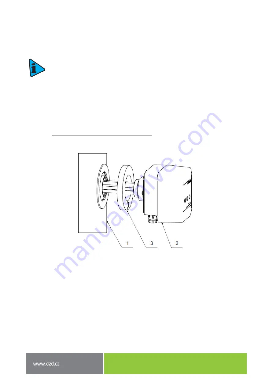
The heating unit shall be mounted in the heater's neck. The end of the thread is provided with 
a  rubber  seal.  To  ensure  better  tightness  we  recommend  the  screw  joint  being  additionally 
sealed with cannabis, a Teflon sealing tape or a mastic sealant (be careful 

 choose a mastic 

sealant  suitable  for  demountable  joints).  Tighten  the  element  properly.  If  the  cable  bushing 
is not directed upright down, loosen the 4 screws on the plastic cover bottom. Turn the cover 

(not  more  than  by  180°)  to  the  desired  position  and  re

-tighten  the  screws.  Check  whether 

the live parts of the wiring do not touch. The sealing ring is mounted last on the metal body 

The space in front of the connection fitting equal to the installation  50 mm must be 
left free for the installation, etc. 

A sealing ring is part of the heating unit package. 


1)


Water heater 

2)


Electrical heating unit TJ 

3)


Sealing ring 

Figure 3


Содержание DRAZICE TJ 6/4 E-3,3 kW

Страница 1: ...W MOUNTED ELECTRICAL HEATING UNIT TJ 6 4 E 3 3 kW TJ 6 4 E 3 75 kW TJ 6 4 E 4 5 kW TJ 6 4 E 6 kW Družstevní závody Dražice strojírna s r o Dražice 69 294 71 Benátky nad Jizerou Phone 420 326 370 990 Fax 420 326 370 980 E mail export dzd cz ...

Страница 2: ...ION 8 2 2 1 BASIC INFORMATION FOR ELECTRICAL INSTALLATION 8 2 2 2 WIRING DIAGRAM 8 2 2 3 APPLICATION DIAGRAM 9 2 2 4 WIRING DESCRIPTION 9 2 3 HEATING UNIT OPERATION 10 2 4 INSPECTION MAINTENANCE 10 2 5 MOST COMMON FAULTS 11 3 IMPORTANT NOTICES 11 3 1 INSTALLATION REGULATIONS 12 3 1 1 OPERATIONAL STATUS 12 3 1 2 OPERATING AND FAULT CONDITIONS LED SIGNALLING ON PCB 13 3 1 3 FAULTY EXTERNAL CONTACT 1...

Страница 3: ...erly instructed by such responsible person The manufacturer reserves the right for engineering modification of the product It is recommended to use the product in indoor environment with air temperatures from 2 C to 45 C and a relative humidity up to 80 Product s reliability and safety is proven by tests implemented by the Engineering Test Institute in Brno Made in the Czech Republic Meaning of pi...

Страница 4: ...S2 RS3 Heating can be carried out in three power steps For example for TJ 6 4 E 6 kW 6 kW 4 kW 2 kW Heating of the individual power steps is indicated by a green translucent colour on the housing cover Figure 2 Figure 9 1 3 VOLTAGE Before interfering with the wiring it is essential to switch off the power supply And wait for at least one minute The voltage of phase L1 is the supply voltage for the...

Страница 5: ...cover Figure 1 Underneath the wiring cover there is a printed circuit board PCB of the control with connection terminals and signals and a safety thermostat The cover can be removed by removing the cover screw Figure 2 Figure 1 Figure 2 Phase switching lights LED L1 LED L2 LED L3 Screw Circuit board Heating element Thermal fuse Wiring cover ...

Страница 6: ...TEMPERATURE SET POINT RANGE HOUSING LENGTH L1 WEIGHT kW hrs A C mm kg TJ 6 4 E 3 3 kW 3 3 3 3 PE N AC 400 V 50Hz 2 6 3 x 10 IP 44 5 74 325 2 2 2 2 2 PE N AC 4 1 1 1 1 PE N AC 8 TJ 6 4 E 3 75 kW 3 3 75 3 PE N AC 400 V 50Hz 2 4 3 x 10 IP 44 5 74 450 2 2 2 5 2 PE N AC 3 5 1 1 25 1 PE N AC 7 TJ 6 4 E 4 5 kW 3 4 5 3 PE N AC 400 V 50Hz 2 3 x 10 IP 44 5 74 500 2 2 3 2 PE N AC 3 1 1 5 1 PE N AC 6 TJ 6 4 E...

Страница 7: ... Tighten the element properly If the cable bushing is not directed upright down loosen the 4 screws on the plastic cover bottom Turn the cover not more than by 180 to the desired position and re tighten the screws Check whether the live parts of the wiring do not touch The sealing ring is mounted last on the metal body The space in front of the connection fitting equal to the installation length 5...

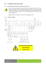
Страница 8: ...n the control cable through the gland and connect according to the diagram Figure 4 The heating unit is connected to the 400 V 230 V 50 Hz mains by a fixed connection with a conductor of the appropriate cross section and the appropriate fuse for the power rating of the heating element Notice Perform the installation in compliance with applicable standards 2 2 2 WIRING DIAGRAM Figure 4 ...

Страница 9: ...1 brown wire L2 phase 2 black wire L3 phase 3 grey wire Conductor max S 4 mm 2 Control external 230 VAC RS1 control switching L1 switches on heating stage I RS2 control switching L2 switches on heating stage II RS3 control switching L3 switches on heating stage III C_N working zero Conductor max S 2 5 mm 3 Fault signalling fuse opening 1 contact S1 S2 Conductor max S 2 5 mm Contact potential free ...

Страница 10: ...nnecting wires to terminals Wires are connected to the Wago terminals on the PCB The tool to use is a flat head screwdriver of the appropriate width The wires are connected from the side Figure 6 Use appropriate clamping force Figure 6 2 3 HEATING UNIT OPERATION Water temperature control is operated performed automatically by an external controller which controls the heating 2 4 INSPECTION MAINTEN...

Страница 11: ... is switched on Have the heating unit repaired by an authorized company Table 2 Figure 7 Do not attempt to repair the failure yourselves Seek either expert or service help It does not take much for an expert to remove the defect When making a repair appointment report the type and serial number you find on the performance plate of your water heater 3 IMPORTANT NOTICES The following cases do not en...

Страница 12: ...6 4 neck shall not exceed 70 mm If longer the variant with an extended cooling circuit has to be used If the length of the neck is within 100 mm it has to be extended on the water side or undercut in a minimum length of 40 mm to the minimal diameter of 50 mm The maximum pressure in the vessel is 10 bar Both the electric and water installation must follow and meet the requirements and regulations r...

Страница 13: ...LED on on cover Input on RS2 LED on on cover Input on RS3 LED on on cover PWR LED on on cove Contact terminal S1 S2 on Heating Operation L1 L2 L3 YES L1 YES L2 YES L3 YES L1 L2 YES L1 L3 YES L2 L3 YES Fault Possible statuses not heating No power L1 L2 L3 NO No power L1 NO Powered L1 L2 L3 NO Overheated opened by emergency thermostat ...

Страница 14: ... order Safety thermostat Printed circuit board Wires Packing ring 3 3 DISPOSAL OF PACKAGING MATERIAL AND NON FUNCTIONING PRODUCT A service fee for providing return and recovery of packaging material has been paid for the packaging in which the product was delivered The service fee was paid pursuant to Act No 477 2001 Coll as amended at EKO KOM a s The client number of the company is F06020274 Take...

Отзывы: