


Verifying the Components
Make sure that you have the following components.
•
SCXI-1334 terminal block
•
SCXI chassis
•
SCXI-1129 switch module
•
1/8 in. flathead screwdriver
•
Numbers 1 and 2 Phillips screwdrivers
•
Long-nose pliers
•
Wire cutter
•
Wire insulation stripper
•
Matrix expansion plug (to expand the number of rows of a matrix)
•
Matrix expansion cable (to expand the number of columns of a matrix)
Connecting Signals
Caution
This module is rated for Measurement Category I and intended to carry
signal voltages no greater than 150 V. This module can withstand up to 800 V
impulse voltage. Do not use this module for connection to signals or for
measurements within Categories II, III, or IV. Do not connect to MAINS supply
circuits (for example, wall outlets) of 115 or 230 VAC. Refer to the
NI Switches
Getting Started Guide
for more information on measurement categories.
When hazardous voltages (>42.4 Vpk/60 VDC) are present on any relay terminal, safety low-
voltage (≤42.4 Vpk/60 VDC) cannot be connected to any other relay terminal
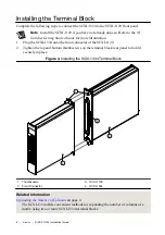
1.
Prepare the signal wire by stripping the insulation no more than 7 mm from the end of the
wire.
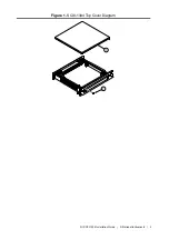
2.
Remove the top cover screw.
3.
Unsnap and remove the top cover.
4.
Loosen the two strain-relief screws on the strain-relief bar.
5.
Run the signal wires through the strain-relief opening.
6.
Insert the stripped end of the wire fully into the terminal. Secure the wire by tightening
the screw of the terminal. No bare wire should extend past the screw terminal. Exposed
wire increases the risk of a short-circuit causing a failure.
7.
Connect the safety earth ground to the safety ground lug.
8.
Tighten the two screws on the strain-relief assembly to secure the cables.
9.
Reinstall the top cover.
10. Replace the top cover screw.
2
|
ni.com
|
NI SCXI-1334 Installation Guide


