


9. Troubleshooting
PROGRAMMABLE AC POWER SOURCE
236
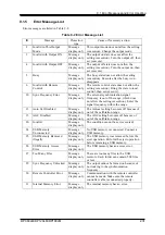
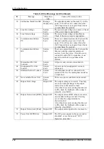
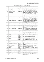
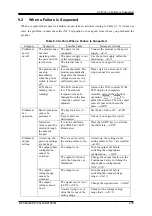
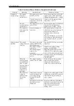
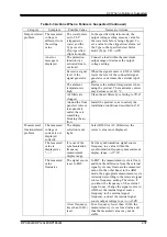
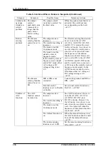
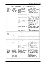
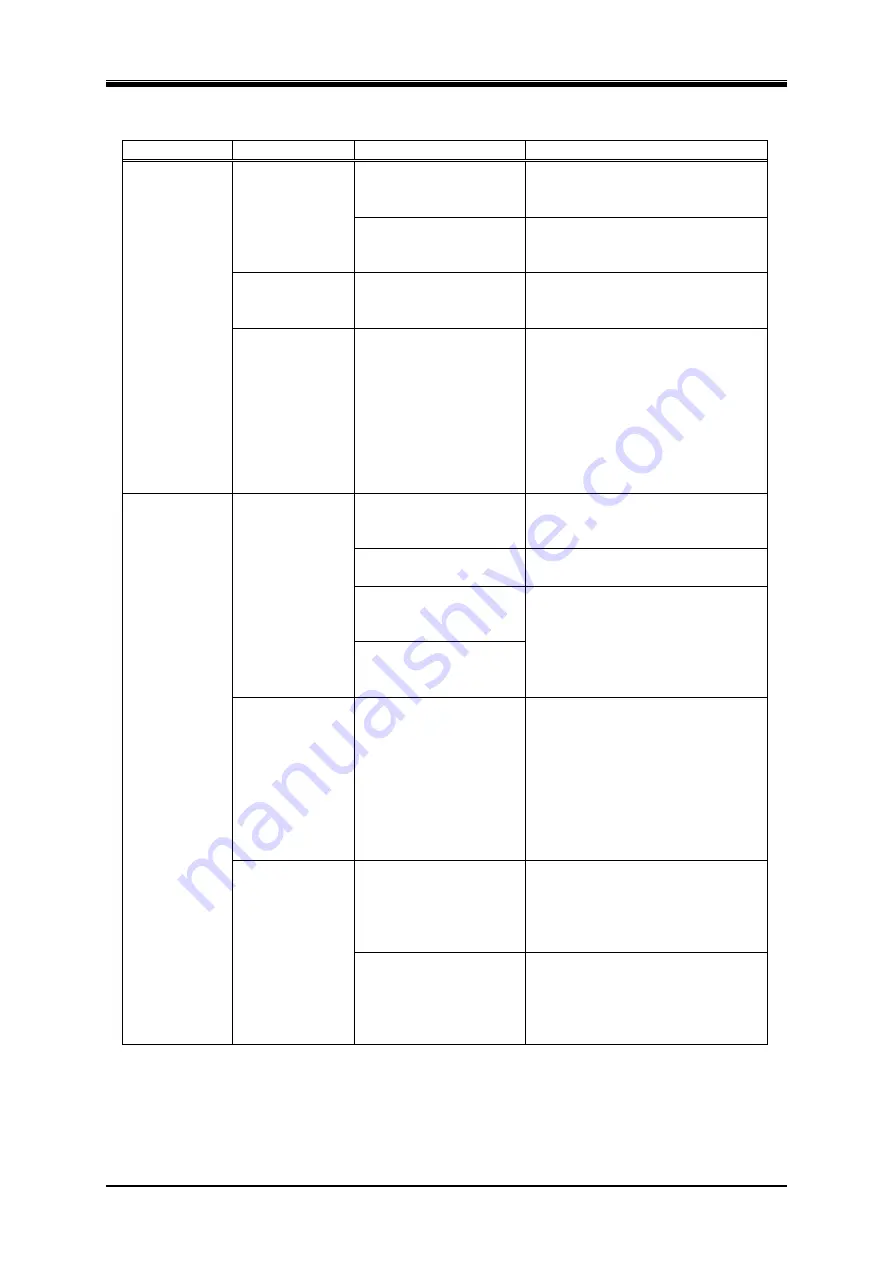
Table 9-3 Actions When a Failure is Suspected (Continued)
Category Symptom Possible
Cause Necessary
Actions
Problem at
output setting
The output
frequency
cannot be set.
The signal source is set
to EXT or SYNC.
This value cannot be set when the
signal source is EXT and SYNC.
Change the signal source.
3.4.2
You are trying to set a
value that is out of the
setting range.
Check for the frequency setting
range limit.
4.1.4
The line
synchronization
cannot be set.
The signal source is not
set to SYNC.
Set the signal source to SYNC and
the external synchronization
signal source to LINE.
4.19
The output on
state cannot be
achieved.
An error message is
on-screen.
The output cannot be turned on
while there is an error message. If
the protection function is
activated, remove the cause.
9.1.2
Press the ENTER key to clear the
error message. When the message
says "System Locked", cycle the
power.
Output-related
problem
The output
voltage does not
come up.
The state is the output
off (the OUTPUT key
LED illuminates)
Press the OUTPUT key to turn the
output on.
The output voltage is
set to zero.
Check for the output voltage
setting.
3.4.5
,
3.4.6
The external signal
source is not
connected.
When the signal source is EXT,
ADD, or VCA, connect the signal
source to the external signal input
terminal, and set the external input
gain appropriately.
4.17
,
4.20
The external input gain
is zero.
When the
external signal
is amplified on
EXT or ADD,
the waveform is
distorted and
the intended
output is not
provided.
The output coupling
mode is the AC mode.
In the AC mode, the waveform
may be distorted as the DC
component removal function
works. Use in the ACDC mode.
The measured
voltage is
different from
the setting
value.
Unnecessary items are
set (for example, the
AC voltage setting
remains for the DC
output).
Check for the setting again. In the
ADD mode, check on the external
input signal and gain setting as
well.
4.20
The limiter is activated
(the limiter icon is
displayed).
For a load with lower impedance,
the limiter is activated to make the
output lower than the setting
value. Check on the limiter
setting.
4.1
Содержание DP060LM
Страница 1: ...PROGRAMMABLE AC POWER SOURCE DP060LM DP120LM DP180LM INSTRUCTION MANUAL NF Corporation...
Страница 2: ......
Страница 3: ...PROGRAMMABLE AC POWER SOURCE DP060LM DP120LM DP180LM INSTRUCTION MANUAL DA00059920 004...
Страница 4: ......
Страница 19: ...DP060LM DP120LM DP180LM 1 1 Outline 1 1 Overview 2 1 2 Series Lineup 2 1 3 Features 3...
Страница 24: ......
Страница 215: ...DP060LM DP120LM DP180LM 197 5 Description of Screen and Menu 5 1 Screen Configuration 198 5 2 Menu Composition 202...
Страница 224: ......
Страница 225: ...DP060LM DP120LM DP180LM 207 6 Remote Control 6 1 Communication Interface 208 6 2 Remote Local State Switching 216...
Страница 239: ...DP060LM DP120LM DP180LM 221 8 Peripherals 8 1 Peripherals Line up 222 8 2 Using in Combination with DIP or RIN 223...
Страница 244: ......
Страница 264: ......
Страница 298: ...11 Specifications PROGRAMMABLE AC POWER SOURCE 280 11 35 Outline Dimensional Drawing Figure 11 2 DP060LM Type2L cabinet...
Страница 300: ...11 Specifications PROGRAMMABLE AC POWER SOURCE 282 Figure 11 4 DP180LM Type5L cabinet...
Страница 307: ...http www nfcorp co jp NF Corporation 6 3 20 Tsunashima Higashi Kohoku ku Yokohama 223 8508 JAPAN...