


DP060LM/DP120LM/DP180LM
xiii
List of Tables
Page
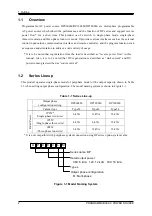
Table 1-1 Series Line-up ........................................................................................................... 2
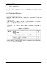
Table 2-1 List of Content ........................................................................................................... 8
Table 2-2 Heat Value ................................................................................................................ 9
Table 2-3 Mass ......................................................................................................................... 9
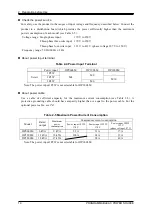
Table 2-4 Power Input Terminal .............................................................................................. 14
Table 2-5 Maximum Power/Current Consumption ................................................................... 14
Table 2-6 Screw Size of Output Terminal ................................................................................ 18
Table 3-1 Component Name (Front) ....................................................................................... 28
Table 3-2 Component Name (Rear) ........................................................................................ 30
Table 3-3 Component Name (Control Panel) .......................................................................... 31
Table 3-4 How the Rated Power Icon is Displayed Depending on the Power Unit Energization
Setting ............................................................................................................................. 34
Table 3-5 Character String Entry List ...................................................................................... 39
Table 3-6 Shortcut Operations ................................................................................................ 40
Table 3-7 Description of the AC/DC Mode .............................................................................. 43
Table 3-8 Description of the Signal Source ............................................................................. 43
Table 3-9 List of the Selectable Combinations of the AC/DC Mode and the Signal Source ..... 44
Table 3-10 The Setting Range per Output Range ................................................................... 46
Table 3-11 Main Measurement Functions ............................................................................... 54
Table 3-12 The Measuring Mode for the Measured Values of the Output Voltage and Output
Current ............................................................................................................................ 55
Table 4-1 Wattage Limiter Value per Phase (Reference value) .............................................. 71
Table 4-2 Parameters of Sequence Function .......................................................................... 74
Table 4-3 Example of Editing Sequence ................................................................................. 77
Table 4-4 Simulation Function Parameters ........................................................................... 105
Table 4-5 Simulation Function Steps and Settable Step Parameters .................................... 106
Table 4-6 Voltage Dip Simulation Edit Example .................................................................... 107
Table 4-7 Voltage Change Simulation Edit Example ............................................................. 108
Table 4-8 Different Output Voltage Settings Depending on Clip Depth Setting Method ........ 133
Table 4-9 Content Saved in Sequence Memory .................................................................... 152
Table 4-10 Content Saved in Simulation Memory ................................................................. 153
Table 4-11 Setting pattern of external control, remote sensing and AGC / Autocal ............... 158
Table 4-12 Setting Range of DC Offset Adjustment Value .................................................... 168
Table 4-13 CONTROL I/O Pin Assignment ........................................................................... 178
Table 4-14 Step Sync Code .................................................................................................. 178
Table 4-15 Memory Specification .......................................................................................... 178
Table 4-16 The Output Terminal Impedance in the Output Off State when the Activation of the
Output Relay is Disabled ............................................................................................... 186
Table 4-17 Setting Items to be Reset .................................................................................... 194
Table 5-1 Component Name (Display Areas on the Screen) ................................................. 198
Содержание DP060LM
Страница 1: ...PROGRAMMABLE AC POWER SOURCE DP060LM DP120LM DP180LM INSTRUCTION MANUAL NF Corporation...
Страница 2: ......
Страница 3: ...PROGRAMMABLE AC POWER SOURCE DP060LM DP120LM DP180LM INSTRUCTION MANUAL DA00059920 004...
Страница 4: ......
Страница 19: ...DP060LM DP120LM DP180LM 1 1 Outline 1 1 Overview 2 1 2 Series Lineup 2 1 3 Features 3...
Страница 24: ......
Страница 215: ...DP060LM DP120LM DP180LM 197 5 Description of Screen and Menu 5 1 Screen Configuration 198 5 2 Menu Composition 202...
Страница 224: ......
Страница 225: ...DP060LM DP120LM DP180LM 207 6 Remote Control 6 1 Communication Interface 208 6 2 Remote Local State Switching 216...
Страница 239: ...DP060LM DP120LM DP180LM 221 8 Peripherals 8 1 Peripherals Line up 222 8 2 Using in Combination with DIP or RIN 223...
Страница 244: ......
Страница 264: ......
Страница 298: ...11 Specifications PROGRAMMABLE AC POWER SOURCE 280 11 35 Outline Dimensional Drawing Figure 11 2 DP060LM Type2L cabinet...
Страница 300: ...11 Specifications PROGRAMMABLE AC POWER SOURCE 282 Figure 11 4 DP180LM Type5L cabinet...
Страница 307: ...http www nfcorp co jp NF Corporation 6 3 20 Tsunashima Higashi Kohoku ku Yokohama 223 8508 JAPAN...