


DP060LM/DP120LM/DP180LM
xi
Figures and Tables
List of Figures
Page
Figure 1-1 Model Naming System ............................................................................................. 2
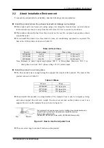
Figure 2-1 How to Use the Adjuster Foot .................................................................................. 9
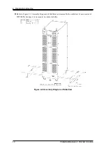
Figure 2-2 Assembly Diagram of Stabilizer ............................................................................. 10
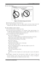
Figure 2-3 Prohibited arrangement method ............................................................................. 11
Figure 2-4 Power Input Terminal ............................................................................................. 16
Figure 2-5 Terminal Block Layout ............................................................................................ 17
Figure 2-6 How to Attach Resin-molded Cover in Single-phase Output .................................. 19
Figure 2-7 How to Attach Resin-molded Cover in Polyphase Output ...................................... 21
Figure 3-1 Component Name (Front) ...................................................................................... 28
Figure 3-2 Component Name (Rear) ....................................................................................... 29
Figure 3-3 Component Name (Control Panel) ......................................................................... 31
Figure 4-1 Step-control Parameters and intra-Step Parameters ............................................. 72
Figure 4-2 Step Behavior ........................................................................................................ 73
Figure 4-3 Stop Phase ............................................................................................................ 76
Figure 4-4 Example of Sequence ............................................................................................ 77
Figure 4-5 Process Flow in Sequence Step ............................................................................ 78
Figure 4-6 Branch Operation/Stop Operation .......................................................................... 78
Figure 4-7 Sequence Edit View ............................................................................................. 100
Figure 4-8 Sequence Control View (Output Off State) .......................................................... 100
Figure 4-9 Sequence Control View (Output On State/Sequence in Execution) ..................... 100
Figure 4-10 Sequence Control View (Output On State/Sequence Stopped) ......................... 101
Figure 4-11 Simulation Function Steps ................................................................................. 105
Figure 4-12 Voltage Dip Simulation Example ........................................................................ 107
Figure 4-13 Voltage Change Simulation Example ................................................................. 108
Figure 4-14 Process Flow through Simulation Steps ............................................................. 109
Figure 4-15 Stop Operation .................................................................................................. 109
Figure 4-16 Simulation Edit View .......................................................................................... 126
Figure 4-17 Simulation Control View (Output Off State, Simulation Stopped) ....................... 127
Figure 4-18 Simulation Control View (Output On State, Simulation Running) ....................... 127
Figure 4-19 Simulation Control View (Output On State, Simulation Stopped) ....................... 127
Figure 4-20 Current Waveform Containing Many Harmonic Components ............................. 128
Figure 4-21 Inrush Current Example ..................................................................................... 130
Figure 4-22 Clipped Sine Wave ............................................................................................ 132
Figure 4-23 USB Memory Folder Structure ........................................................................... 154
Figure 4-24 Sensing input terminals ..................................................................................... 159
Figure 4-25 The Message Window to be Shown Before the Automatic Output-On After the
Содержание DP060LM
Страница 1: ...PROGRAMMABLE AC POWER SOURCE DP060LM DP120LM DP180LM INSTRUCTION MANUAL NF Corporation...
Страница 2: ......
Страница 3: ...PROGRAMMABLE AC POWER SOURCE DP060LM DP120LM DP180LM INSTRUCTION MANUAL DA00059920 004...
Страница 4: ......
Страница 19: ...DP060LM DP120LM DP180LM 1 1 Outline 1 1 Overview 2 1 2 Series Lineup 2 1 3 Features 3...
Страница 24: ......
Страница 215: ...DP060LM DP120LM DP180LM 197 5 Description of Screen and Menu 5 1 Screen Configuration 198 5 2 Menu Composition 202...
Страница 224: ......
Страница 225: ...DP060LM DP120LM DP180LM 207 6 Remote Control 6 1 Communication Interface 208 6 2 Remote Local State Switching 216...
Страница 239: ...DP060LM DP120LM DP180LM 221 8 Peripherals 8 1 Peripherals Line up 222 8 2 Using in Combination with DIP or RIN 223...
Страница 244: ......
Страница 264: ......
Страница 298: ...11 Specifications PROGRAMMABLE AC POWER SOURCE 280 11 35 Outline Dimensional Drawing Figure 11 2 DP060LM Type2L cabinet...
Страница 300: ...11 Specifications PROGRAMMABLE AC POWER SOURCE 282 Figure 11 4 DP180LM Type5L cabinet...
Страница 307: ...http www nfcorp co jp NF Corporation 6 3 20 Tsunashima Higashi Kohoku ku Yokohama 223 8508 JAPAN...