


8.2 When a Failure is Suspected
DP Series
231
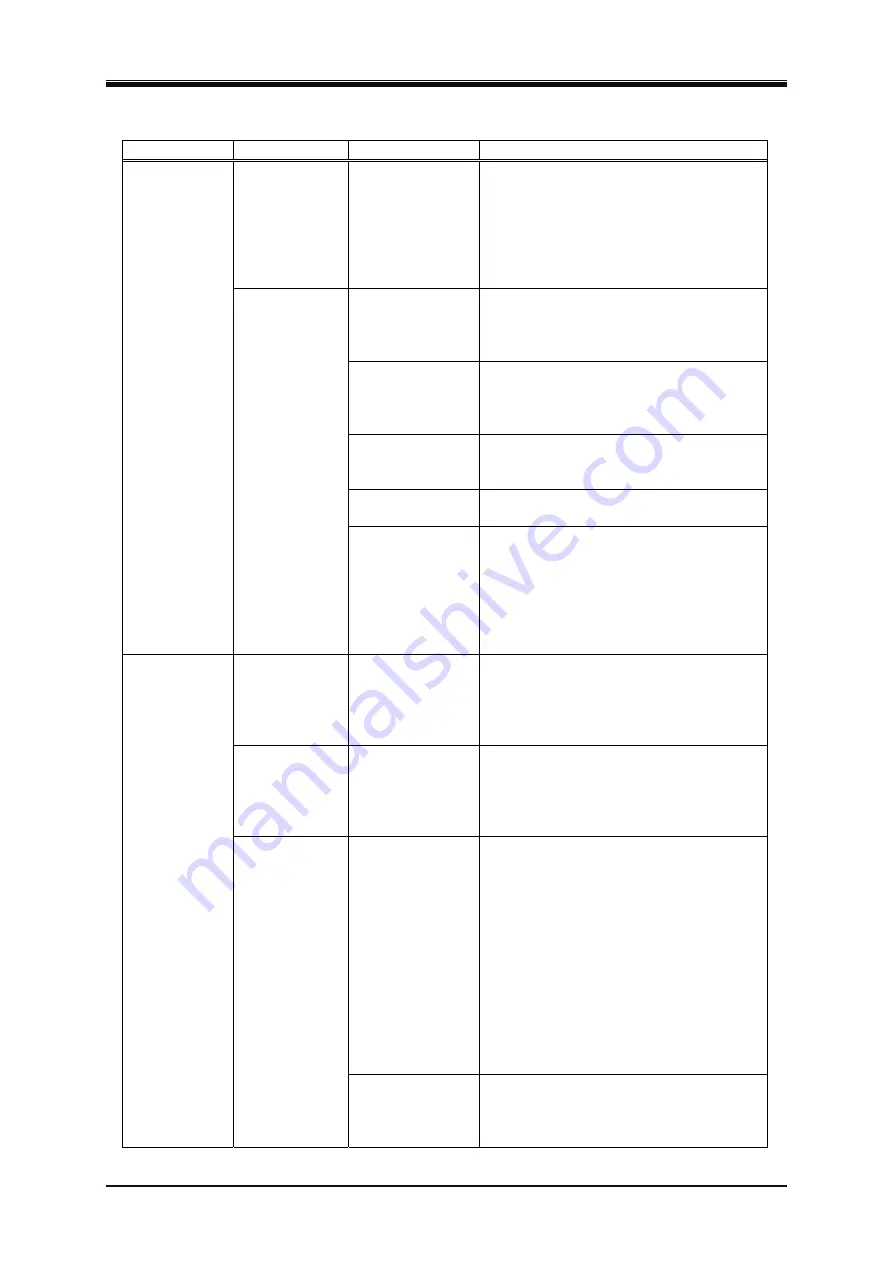
Table 8-3 Actions When a Failure is Suspected (Continued)
Category
Symptom
Possible Cause
Necessary Actions
The measured
voltage is
different from
the setting
value.
The waveform is
set to CLP
(clipped sine
wave) and the
Type is set to
Clip (specified
clip ratio mode).
In the specified clip ratio mode, the
output voltage setting means a value for
the waveform before being clipped. To
set a value for the clipped waveform, set
the Type to the specified crest factor
mode (Type: CF).
→
The protection
function was
activated due to
overload.
Connect a load within the maximum
output range or decrease the output
voltage setting.
Excessive signal
level of the
signal generator.
When the signal source is EXT or ADD,
lower the level of the connected signal
generator or decrease the external input
gain.
The ambient
temperature is
high.
Decrease the ambient temperature when
using the product. The maximum current
may decrease over 40 °C.
Air filters are
clogged.
Clean the air filters by referring to
.
Output-related
problem
An error
message is
displayed.
Around the front
panel air inlet or
rear panel air
outlet, there is
something
blocking the air
flow.
Install the product so as to satisfy the
installation conditions described in
.
The measured
voltage or
current is not
displayed
correctly.
The display
selection is not
right.
Select RMS for AC. Otherwise, the
correct value is not displayed.
The measured
value is
displayed as
"----".
It is out of the
synchronization
frequency
measurement
display range.
Set the synchronization signal source
frequency to a value within the
synchronization frequency measurement
display range.
→
The signal source
is set to EXT.
In EXT, the measurement cycle is fixed,
and thus the difference from the external
signal cycle may fluctuate the measured
value. On the other hand, in the ADD
mode, the appropriate measurement cycle
is decided according to the internal signal
source frequency setting. Therefore, if
you know the frequency of the external
signal to use, change the signal source to
ADD, set the internal signal source
frequency to the external signal
frequency, and set the internal signal
source output voltage to zero.
→
Measurement
function-related
problem
The measured
value
fluctuates.
A low frequency
(less than 10 Hz)
is set.
For a frequency lower than 10 Hz, the
measurement cycle is a fixed value and
thus the measured value may not be
stable.
Содержание DP015S
Страница 1: ...PROGRAMMABLE AC POWER SOURCE DP Series INSTRUCTION MANUAL NF Corporation ...
Страница 2: ......
Страница 3: ...PROGRAMMABLE AC POWER SOURCE DP Series INSTRUCTION MANUAL DA00027113 001 ...
Страница 4: ......
Страница 18: ......
Страница 19: ...DP Series 1 1 Outline 1 1 Overview 2 1 2 Series Line up and Polyphase System Configuration 2 1 3 Features 4 ...
Страница 24: ...1 Outline PROGRAMMABLE AC POWER SOURCE 6 ...
Страница 215: ...DP Series 197 5 Description of Screen and Menu 5 1 Screen Configuration 198 5 2 Menu Composition 202 ...
Страница 224: ...5 Description of Screen and Menu PROGRAMMABLE AC POWER SOURCE 206 ...
Страница 225: ...DP Series 207 6 Remote Control 6 1 Communication Interface 208 6 2 Remote Local State Switching 214 ...
Страница 237: ...7 8 Replacement Air Filter DP Series 219 フロントグリル フロントグリル Front grill 1 Front grill 2 Figure 7 2 Front Grills ...
Страница 238: ...7 Options PROGRAMMABLE AC POWER SOURCE 220 ...
Страница 239: ...DP Series 221 8 Troubleshooting 8 1 Error Messages and Error Handling 222 8 2 When a Failure is Suspected 229 ...
Страница 298: ......
Страница 300: ......
Страница 302: ......
Страница 303: ......
Страница 304: ...http www nfcorp co jp NF Corporation 6 3 20 Tsunashima Higashi Kohoku ku Yokohama 223 8508 JAPAN ...