Copyright © 2022 NEXCOM International Co., Ltd. All Rights Reserved.
13
FTA5180 Series User Manual
Chapter 2: Jumpers and Connectors
Pin
Definition
Pin
Definition
1
GND
2
GND
3
GND
4
P12V
5
P12V
6
P12V
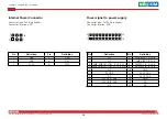
Internal Power Connector
Connector type: 2x3 6-pin header
Connector location: CN11
Pin
Definition
Pin
Definition
1
NC
2
SMB-ALERT_A_CAB
3
NC
4
SMB-ALERT_B_CAB
5 SMB_PMBUS1_STBY_LVC3_R_SCL
6
PRESENT_IN_A_CAB
7 SMB_PMBUS1_STBY_LVC3_R_SDA
8
PRESENT_IN_B_CAB
9
NC
10
GND
11
PS_ON_R
12
P3V3_AUX
13
NC
14
P3V3_AUX
15
PW_OK_A_CAB
16
GND
17
PW_OK_B_CAB
18
NC
19
NC
20
NC
Power signal to power supply
Connector type: 2x10 20-pin header
Connector location: CN7
1
6
1
19
2
20


