Copyright © 2023 NexCOBOT Co., Ltd. All Rights Reserved.
10
NEX 813 User Manual
Chapter 2: Jumpers and Connectors
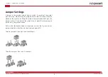
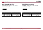
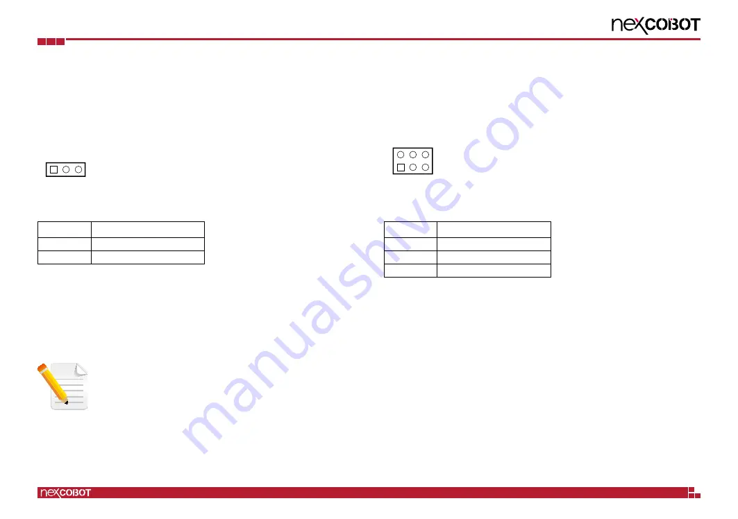
COM1 Ring/+5V/+12V Selection
Connector type: 2x3 6-pin header
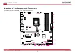
Connector location: COM1_V1
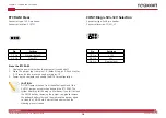
RTC RAM Clear
Connector type: 1x3 3-pin header
Connector location: CLRTC1
Pin
Settings
1-2 On
Normal (default)
2-3 On
Clear RTC
Erase the RTC RAM
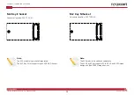
1. Unplug the power cord when the computer is switched off.
2. Move the jumper cap from pins 1-2 (default) to pins 2-3 and stay for
5–10 seconds, then move the cap back to pins 1-2.
3. Power on the computer and enable the BIOS for configuration.
CAUTION:
DO NOT remove the cap from the default position of the
CLRTC1 jumper, except when cleaning the RTC RAM. The
system boot may fail if doing so. Moreover, if you fail to clean
the CMOS data by removing the jumper cap, please remove
the onboard battery first and then remove the jumper again
to clean the CMOS data. Reinstall the battery when the
cleaning process is done.
1
3
Pin
Settings
1-2 On
+12V
3-4 On
+5V
5-6 On
Ring (default)
2
6
1 5

