INFCP and INFCP-xxxB
INFINITY
®
C Process Panel Meter
Operator’s Manual
NEWPORT
Electronics, Inc.
http://www.newportUS.com/manuals
Downloaded from
Elcodis.com
electronic components distributor
Страница 1: ...INFCP and INFCP xxxB INFINITY C Process Panel Meter Operator s Manual NEWPORT Electronics Inc http www newportUS com manuals Downloaded from Elcodis com electronic components distributor ...
Страница 2: ...ty for any errors it contains and reserves the right to alter specifications without notice WARNING These products are not designed for use in and should not be used for patient connected applications TRADEMARK NOTICE a newportUS com and the Meter Case Bezel Design are trademarks of NEWPORT Electronics Inc PATENT NOTICE This product is covered by one or more of the following patents U S Pat No Des...
Страница 3: ...ting a display color Setting the setpoint s active band Selecting a latched or unlatched operation Setting setpoint deadbands Enabling disabling setpoint changes Enabling disabling the RESET button in the Run Mode Optional Procedures Setting input resolution Enabling disabling analog output Selecting analog output as current or voltage Selecting analog output or proportional control Selecting prop...
Страница 4: ...ion setpoint deadbands output configuration analog output proportional band manual reset analog output scaling lock out configuration display brightness Display messages Meter menu sub menu messages Setpoint configuration messages Specifications Factory Preset Values 1 2 3 4 5 6 7 8 9 Refer to section Introduction About the Meter Getting Started Configuring the Meter Display Messages Menu Configur...
Страница 5: ...ting Sensor Inputs 15 3 5 Connecting Main Power 18 3 6 Conecting External Tare Switch 20 3 7 Connecting Analog and Relay Outputs 20 SEC 4 CONFIGURING THE METER 22 4 1 Selecting the Input Type 22 4 2 Selecting a Decimal Point Position 23 4 3 Selecting Reading Scale and Offset 23 4 3 1 Scaling with Known Loads 24 4 3 2 Scaling without Known Loads 27 4 4 Using Reading Configuration 28 4 4 1 Enabling ...
Страница 6: ...g Output as Current or Voltage 36 4 10 3 Selecting Analog Output or Proportional Control 36 4 11 Selecting Proportional Band 38 4 12 Using Manual Reset 40 4 13 Using Output Scale and Offset 41 4 14 Using Lock Out Configuration 43 4 14 1 Enabling or Disabling the RESET Button in the Run Mode 43 4 14 2 Enabling or Disabling Setpoint Changes 43 4 14 3 Setpoints Display Function Software Version or Se...
Страница 7: ...n 15 3 8 4 Wire DC Input Connections with Internal Excitation 16 3 9 4 Wire DC Input Connections with External Excitation 16 3 10 DC Current Input Connectiions with Internal Excitation 17 3 11 DC Current Input Connections with External Excitation 17 3 12 DC Current Input Connections with Current Source 18 3 13 Main Power Connections AC Powered Unit 18 3 14 Main Power Connections DC Powered Unit 19...
Страница 8: ...nit 19 4 1 Range Selection Dip Switch Positions for Regular Voltage Input 24 4 2 Range Selection Dip Switch Positions for Millivolt and Milliamp Input 24 4 3 Natural Gain 27 4 4 Input Resolution Multiplier 27 5 1 Display Messages 45 6 1 Menu Configuration Displays 46 6 2 Run Mode Displays 50 7 1 Setpoint Configuration Displays 51 8 1 Color Chart for dc Power 55 9 1 Factory Preset Values 57 Downloa...
Страница 9: ...rmation that is important to successfully setup and use the Programmable Digital Meter CAUTION or WARNING tells you about the risk of electric shock CAUTION WARNING or IMPORTANT tells you of circumstances or practices that can effect the meter s functionality and must refer to accompanying documents TIP Provides you helpful hints Note Downloaded from Elcodis com electronic components distributor ...
Страница 10: ...viii Downloaded from Elcodis com electronic components distributor ...
Страница 11: ...ing agent The carrier will not honor any claims unless all shipping material is saved for their examination After examining and removing contents save packing material and carton in the event reshipment is necessary Verify that you receive the following items in the shipping box QTY DESCRIPTION 1 Programmable Digital Meter indicator controller with all applicable connectors attached 1 Owner s Manu...
Страница 12: ... switch shall not be incorporated in the main supply cord Furthermore to provide protection against excessive energy being drawn from the main supply in case of a fault in the equipment an overcurrent protection device shall be installed Do not exceed voltage rating on the label located on the top of the instrument housing Always disconnect power before changing signal and power connections Do not...
Страница 13: ...critical processes A mechanical lockout has been included to guard against unauthorized changes 2 2 FEATURES The following is a list of standard features 4 digit three color Programmable Big LED display or 4 digit Standard LED Display NEMA 4 Type 4 Front Bezel 0 03 accuracy 8 DC input ranges 0 100 mV 50 mV 0 5 V 1 5 V 0 10 V 5 V 0 20 mA and 4 20 mA 5 10 12 or 24 Vdc sensor excitation Peak detectio...
Страница 14: ...oof Cover SPC18 NEMA 4 Splash Proof Cover NEW Accessories TP1A Trimplate panel adaptor Adapts DIN1A DIN2A cases to larger panel cutouts RP18 19 In Rack Panel for one 1 1 8 DIN instrument RP28 19 In Rack Panel for two 2 1 8 DIN instruments RP38 19 In Rack Panel for three 3 1 8 DIN instruments Downloaded from Elcodis com electronic components distributor ...
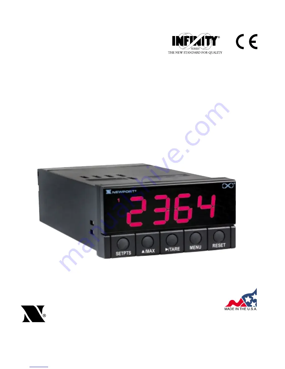
Страница 15: ...dard Display These meter display windows both versions light when appropriate 1 Setpoint 1 status 2 Setpoint 2 status 5 Pushbuttons for programming the meter 1 2 RESET MENU TARE MAX SETPTS Digital LED Display 1 9 9 9 or 9 9 9 9 4 digit three color programmable 21 mm 0 83 high LED display with programmable decimal point Digital LED Display 1 9 9 9 or 9 9 9 9 14 segment 13 8 mm 0 54 high LED display...
Страница 16: ...n MAX Button In the Run Mode this button will recall the PEAK reading since the last press of the RESET button In the Configuration Mode press this button to change the value of the flashing digit shown on the display and or toggle between menu choices such as R 1 T or R 1 N on RD CF menu When configuring your setpoint values press the MAX button to advance the flashing digit s value from 0 to 9 b...
Страница 17: ...the Run Mode press the RESET button to reset tare if any The meter shows T RST and returns to the Run Mode In the Configuration Mode press the RESET button once to review the previous menu Press the RESET button twice to perform a hard reset and return to the Run Mode In the Peak Mode press the RESET button to reset peak values The meter shows PK RS and returns to the Run Mode In the Setpoint Mode...
Страница 18: ...escribing the connectors on the back of the meter Table 2 2 on the following page gives a brief description of each connector at the back of the meter Figure 2 3 Connector Label AC Powered and DC Powered Detail Downloaded from Elcodis com electronic components distributor ...
Страница 19: ...powered units TB1 9 AC earth ground DC power return on DC powered units TB1 10 Analog voltage output TB1 11 Analog current output TB1 12 Analog return TB2 1 E Negative excitation connection from meter 5 10 12 V TB2 2 E Positive excitation connection from meter 5 10 12 V TB2 3 20 mA connection for analog input TB2 4 Not used TB2 5 24 V output connection TB2 6 S Positive signal input TB2 7 S Negativ...
Страница 20: ...c excitation C C C Settings for Input Ranges 0 100 mV DC O C O O O 50 mV DC O C O C O 5 Vdc C O O C C 0 10 Vdc C O O O C 0 20 mA DC O C C O O The display must also be configured to the selected input type after setting the DIP switches see Section 4 1 Selecting the Input Type 2 6 DISASSEMBLY You may need to open up the meter for one of the following reasons To check or change the 115 or 230 Vac po...
Страница 21: ...ing This device must only be reconfigured by a specially trained electrician with corresponding qualifications Failure to follow all instructions and warnings may result in injury 1 Remove the main board from the case Refer to Section 2 6 2 Locate the solder jumpers W1 W2 and W3 located near the edge of the main board alongside the transformer 3 If your power requirement is 115 Vac solder jumpers ...
Страница 22: ...ure 3 2 Main Board Jumper Positions Figure 3 3 Upper Isolated Analog Output Option Board Installation P1 TB5 Attach cable to P1 E D C B A MAIN BOARD T1 DISPLAY BOARD S2 S2 S4 S1 S3 S3 TP11 TP1 TP2 TP3 TP4 TP5 TP6 TP7 TP8 TP9 TP10 J1 TB1 TB2 Refer to table 3 1 D C B A Downloaded from Elcodis com electronic components distributor ...
Страница 23: ... calibration procedure Test pins TP1 TP11 are for testing purposes Do not use as reading errors may result S4 A Factory default jumper installed Table 3 1 S3 Jumper Functions Jumper Description S3 A Install to enable front panel push buttons Remove to disable all front panel push buttons S3 B Removed Install for factory calibration only S3 C Removed Not used S3 D Removed Not used S3 E If installed...
Страница 24: ...racket to secure 4 Proceed to Section 3 4 to connect your sensor input and main power Figure 3 5 Panel Cut Out NEW STYLE MOUNTING BRACKET FRONT BEZEL CASE REAR COVER REMOVED PANEL CUT OUT OLDER STYLE MOUNTING BRACKET 2 PCS GASKET PRODUCT LABEL CONNECTOR LABEL 45 00 0 61 0 00 1 772 024 000 92 00 0 81 0 00 3 622 032 000 PANEL THICKNESS 1 5 R 06 4 PLCS 6 4 25 MAX 0 8 03 MIN NOTE Dimensions in Millime...
Страница 25: ...rs Figure 3 6 3 Wire DC Input Connections with Internal Excitation Figure 3 7 3 Wire DC Input Connections with External Excitation TB2 E E 20mA N C 24V S S N C 1 2 3 4 5 6 7 8 EXTERNAL SUPPLY TB2 1 2 3 4 5 6 7 8 EXC SIG COM E E 20mA N C 24V S S N C Downloaded from Elcodis com electronic components distributor ...
Страница 26: ...ns with Internal Excitation Figure 3 9 Wire DC Input Connections with External Excitation TB2 E E 20mA N C 24V S S N C 1 2 3 4 5 6 7 8 SENSOR OUTPUT EXTERNAL SUPPLY TB2 1 2 3 4 5 6 7 8 E E 20mA N C 24V S S N C VOLTAGE EXCITATION OUTPUT Downloaded from Elcodis com electronic components distributor ...
Страница 27: ...ns with Internal Excitation Figure 3 11 DC Current Input Connections with External Excitation TB2 1 2 3 4 5 6 7 8 4 20mA Transmitter E E 20mA N C 24V S S N C EXTERNAL SUPPLY TB2 1 2 3 4 5 6 7 8 E E 20mA N C 24V S S N C 4 20mA Transmitter Downloaded from Elcodis com electronic components distributor ...
Страница 28: ...only be installed by a specially trained electrician with corresponding qualifications Failure to follow all instructions and warnings may result in injury Figure 3 13 Main Power Connections AC Powered Unit TB1 TB2 1 2 3 4 1 2 3 4 5 6 7 8 9 10 5 6 7 8 11 12 FUSE EARTH GROUND GREEN WIRE AC Power Check for proper Earth grounding in the power distribution system single phase SWITCH LINE NEUTRAL EARTH...
Страница 29: ...ble 8 1 Color Chart in the Specifications Section for Display Color Intensity Excitation Voltage and Current and Analog Output Isolated Option Failure to use proper ratings may result in damaging the unit Figure 3 14 Main Power Connections DC Powered Unit DC DC DC POWER TB1 TB2 1 2 3 4 1 2 3 4 5 6 7 8 9 10 5 6 7 8 11 12 WIRE COLORS TB1 AC POWER EUROPE USA 7 AC Line Brown Black 8 AC Neutral Blue Wh...
Страница 30: ... with analog or dual relay or isolated analog output refer to the following drawings for output connections Figure 3 16 Analog Output Connections TB1 TB2 ANALOG VOLTAGE 1 2 3 4 1 2 3 4 5 6 7 8 9 10 5 6 7 8 11 12 0 10V dc ANALOG CURRENT 0 20mA or 4 20mA ANALOG RTN TB1 TB2 1 2 3 4 1 2 3 4 5 6 7 8 9 10 5 6 7 8 11 12 J1 1 2 3 4 EXTERNAL TARE SWITCH CLOSED OPEN S1 Downloaded from Elcodis com electronic...
Страница 31: ...18 Isolated Analog Output Connections 0 10VDC 0 20mA 4 20mA OR 1 2 3 TB5 TB1 TB2 1 2 3 4 1 2 3 4 5 6 7 8 5 6 7 8 9 10 11 12 Relay 1 Relay 2 N O 1 N C 1 COM1 N O 2 N C 2 COM2 TB1 1 2 3 4 5 6 7 8 9 10 11 12 TB2 1 2 3 4 5 6 7 8 EXTERNAL LOAD N L FUSE NO2 COM2 Downloaded from Elcodis com electronic components distributor ...
Страница 32: ...k of your meter Refer to Table 2 3 1 Press the MENU button The meter shows INPT 2 Press the TARE button The meter flashes one of the following 0 20 for 4 20 mA dc Default 100M for 0 100 mV dc 50M for 50 mV dc 10V for 0 10 Vdc 5V for 5 Vdc 3 Press the ßMAX button to scroll through available choices 4 Press the MENU button to store your choice The meter momentarily shows STRD followed by DEC P Decim...
Страница 33: ...your choice The meter momentarily shows STRD followed by the next menu RD S O Reading Scale and Offset Or you can press the RESET button to abort and go back to the DEC P menu 4 3 SELECTING READING SCALE AND OFFSET RD S 0 Refer to Table 6 1 for a summary list of menu configuration To scale the meter to show readings in engineering units There are two methods One method is to scale with known input...
Страница 34: ...ermine correct position of these switches Once Dip switches have been positioned correctly apply power Proceed to the RD CF Reading Configuration and set R2 equal to the value in the right hand column of the chart Table 4 1 Range Selection Dip Switch Positions For Regular Voltage Input Table 4 2 Range Selection Dip Switch Positions For Millivolt Milliamp Input Table 4 1 Range Selection Dip Switch ...
Страница 35: ... input 4 Press the TARE button again The meter shows last stored value for Input 1 5 Press the TARE button once more The meter shows the actual signal being received 6 Press the MENU button to store this value as IN1 Input 1 The meter shows RD1 Read 1 RD1 Read 1 is the desired display reading at Input 1 7 Press the TARE button The meter shows the last stored value for Read 1 8 Press the ßMAX butto...
Страница 36: ... Press the MENU button to store Input 2 value The meter shows RD 2 Read 2 RD 2 Read 2 is the desired display reading at input 2 15 Press the TARE button The meter shows the last stored value for Read 2 16 Press the ßMAX button to change the value of your digits 17 Press the TARE button to scroll horizontally to the next digit 18 Press the MENU button to store value as RD 2 Read 2 The meter momenta...
Страница 37: ...lculate IN1 and IN 2using the transducer output span and the following equation IN Sensor Output x Natural Gain x Multiplier Table 4 3 Natural Gain 2 Determine the multiplier by the Input Resolution setting R 2 in the RD CF menu and the input range selected Typically R 2 4 is suitable for most applications Table 4 4 Input Resolution Multiplier Input Range R 2 4 R 2 3 R 2 2 R 2 1 R 2 0 0 to 100 mV ...
Страница 38: ...ge the value of your digits 8 Press the TARE button to scroll horizontally to the next digit 9 Press the MENU button to store this value The meter shows RD1 10 Press the TARE button The meter shows the last value for read 1 Repeat steps 7 8 and 9 until RD1 IN 2and RD 2 have been displayed verified changed if necessary and stored 4 4 USING READING CONFIGURATION RD CF Refer to Table 6 1 for a summar...
Страница 39: ...e steps 1 Press the MENU button until RD CF displays then press the TARE button twice or Press the TARE button from R 1 One of the following displays default is R 2 4 R 2 4 10 µV for Unipolar inputs 25 µV for Bipolar inputs R 2 0 1 µV for Unipolar inputs 5 µV for Bipolar inputs R 2 1 2 µV for Unipolar inputs 10 µV for Bipolar inputs R 2 2 3 µV for Unipolar inputs 15 µV for Bipolar inputs R 2 3 5 µ...
Страница 40: ...owed by COLR menu 4 5 Selecting a Display Color COLR Refer to Table 6 1 for a summary list of menu configuration Selecting Display Color is not active unless your meter is a Version B To select a display color follow these steps 1 Press the MENU button until the meter shows COLR 2 Press the TARE button The meter shows one of the following GRN RED AMBR 3 Press the ßMAX button to scroll between avai...
Страница 41: ...ows one of the following S 1 A Active above the setpoint Default S 1 B Active below the setpoint 3 Press the ßMAX button to toggle between available choices 4 Press the TARE button to select if Setpoint 1 is latched or unlatched or press the MENU button to store your selection 4 6 2 Selecting if Setpoint 1 is Latched or Unlatched 1 Press the MENU button until S1 CF displays then press the TARE but...
Страница 42: ...following S 1 A Active above the setpoint Default S 1 B Active below the setpoint 3 Press the ßMAX button to toggle between available choices 4 Press the TARE button to select if Setpoint 2 is latched or unlatched or press the MENU button to store your selection and enter S1 DB Setpoint 1 Deadband 4 7 2 Selecting if Setpoint 2 is Latched or Unlatched 1 Press the MENU button until S2 CF displays th...
Страница 43: ...mentarily shows STRD followed by S2 DB Setpoint 2 Deadband 4 9 SETTING THE SETPOINT 2 DEADBAND S2 DB Refer to Table 6 1 for a summary list of menu configuration Setpoint 2 Deadband S2 DB is not active unless your meter has dual relay output capabilities The LED s will display whether the S2 DB is active or not The Setpoint 2 default deadband is 0003 To change the deadband hysteresis of Setpoint 2 ...
Страница 44: ...IGNAL LEVEL SIGNAL LEVEL SIGNAL LEVEL ON ON OFF ON ON ON ON ON ON ON ON ON OFF OFF ON OFF OFF OFF OFF ACTIVE BELOW ACTIVE ABOVE ACTIVE BELOW WITH DEADBAND 3 ACTIVE ABOVE WITH DEADBAND 3 ACTIVE BELOW LATCHED ACTIVE ABOVE LATCHED SETPOINT SETPOINT SETPOINT NOTE DEADBAND WORKS AS HYSTERISIS 3 3 DEADBAND Note Downloaded from Elcodis com electronic components distributor ...
Страница 45: ...put is current or voltage To select if the analog output is regular or proportional 4 10 1 Enabling or Disabling the Analog Output To enable or disable the analog output follow these steps 1 Press the MENU button until the meter shows OT CF 2 Press the TARE button The meter shows one of the following O 1 E Analog output enabled Default O 1 D Analog output disabled 3 Press the ßMAX button to toggle...
Страница 46: ...ut Scale and Offset 4 10 3 Selecting Analog Output or Proportional Control Use this section to select if the meter will transmit an analog signal proportional to the display readings or proportional to the error signal between the display reading and Setpoint 1 Proportional Control Analog Option is not available for models without Relay Option 1 Press the MENU button until it shows OT CF then pres...
Страница 47: ...CTING 4 Press the ßMAX button to toggle between available choices 5 Press the MENU button to store your selections The meter momentarily shows STRD followed by P BND Proportional Band Additionally if you select O 2 V Analog output to be voltage press the TARE button One of the following displays O 5 F Proportional 0 10 V analog output O 5 H Proportional 0 5 V analog output 6 Press the ßMAX button ...
Страница 48: ...ignal that drives the controller to full on e g 20 mA out for 4 20 mA Figure 4 2 Controller Output The second point of interest is the magnitude of the error signal that drives the controller output to full off e g 4 mA out on 4 20 mA These two 2 points need not be equally spaced on either side of the zero error point The third is the factor Offset and it is the output value of the controller whic...
Страница 49: ... displayed until 0 3 A then press ßMAX unit will show 0 3 P Pressing the MENU button will store the selection 2 Press the TARE button The meter shows last previously stored 4 digit number 0000 through 9999 with flashing 4th digit 3 Press the ßMAX button to change the value of the flashing digit If you continue to press the ßMAX button the flashing digit s value continues to change 4 Press the TARE...
Страница 50: ...nt to enter into Manual Reset M RST The value of M RST must be less than P BND 2 Larger values will not be accepted and the meter will display ER4 flashing 1 Press the MENU button until M RST displays This menu M RST and P BND will show up if 0 3 P on OT CF 2 Press the TARE button The meter shows the last previously stored 4 digit number 1999 through 9999 with flashing 4th digit 3 Press the ßMAX b...
Страница 51: ...4 digit number 1999 through 9999 with flashing 4th digit 4 Press the ßMAX button to change the digits 5 Press the TARE button to scroll to the next digit 6 Press the MENU button to store your selection OUT 1 Output 1 displays This starting analog signal corresponds to your Read 1 display 7 Press the TARE button Selected output displays If you select O 2 V for voltage the maximum signal you may sel...
Страница 52: ...on The meter shows selected output If you select O 2 V for voltage the maximum signal you may select is 10 00 for an 0 10 Vdc signal output If you select O 2 C for current the maximum signal you may select is 20 00 for a 0 20 or 4 20 mA DC signal output 16 Press the ßMAX button to change the value of the flashing digit If you continue to press the ßMAX button the flashing digit s value continues t...
Страница 53: ...disable the RESET button in the Run Mode 3 Press the ßMAX button to toggle between available choices 4 Press the MENU button to store the changes The meter shows STRD if the new value is different otherwise the meter shows BRIT and returns to the Run Mode 4 14 2 Enabling or Disabling SETPOINT Changes 1 Press the MENU button until the meter shows LK CF after OT S O 2 Press the TARE button twice The...
Страница 54: ...e will not be available and SETPTS button will always display the meter s firmware version These units will have OL overload or OPN memory indicated by Alarm 1 2 LED displays LEDs can be reset by pressing MENU then RESET button or by Power OFF then ON 4 15 USING DISPLAY BRIGHTNESS CONFIGURATION Changing Display Brightness is not active unless your meter is a Version B 1 Press the MENU button until...
Страница 55: ...ST Manual Reset ER4 Manual Reset Error OT CF Output Configuration OT S O Output Scale and Offset LK CF Lock Out Configuration BRIT Display Brightness OL Overload Signal OL Overload Signal RS OF Resolution Overflow 999 Value Overflow in Setpoint Menu Peak Routines 1999 Value Overflow in Setpoint Menu Peak Routines ER1 2 Coordinate Format Programming Error PEAK Peak Value PK RS Peak Reset T RS Tare ...
Страница 56: ...n and can not be changed with ßMAX If ßMAX is pressed unit can scroll through digits with TARE Enter new value and Shows prior value entered and flashing digit Changes the value show RD1 Scrolls to the next digit of the flashing digit Enter new value and Shows prior value entered and flashing digit Changes the value show IN2 Scrolls to the next digit of the flashing digit If TARE is pressed actual...
Страница 57: ...on for bipolar R 2 3 5 µV resolution for unipolar 25 µV resolution for bipolar R 2 4 10 µV resolution for unipolar 25 µV resolution for bipolar Note 3 µV resolution means if your input is 0 30 mV at 30 mV the display shows 9999 R 3 R 3 F Filtered value R 3 U Unfiltered value Show input choices GRN Green Display Color Selection RED Red COLR AMBR Amber S 1 S 1 A Active above Setpoint 1 Configuration...
Страница 58: ...tput is disabled OT CF 0 2 0 2 C Analog output is current 0 2 V Analog output is voltage 0 3 0 3 A Regular analog output 0 3 P Proportional analog output 0 4 0 4 D Proportional analog is direct acting shown if menu 0 3 P 0 4 R Proportional analog is reverse acting 0 5 0 5 F Analog output is 0 10 Vdc shown if menu 0 2 V 0 5 H Analog output is 0 5 Vdc If you select 0 2V and 0 3 P you may select your...
Страница 59: ...ffset Shows RD1 OT S O Shows prior value entered and flashing digit Changes the value Scrolls to the next digit of the flashing digit Enter new value and Shows prior value entered and flashing digit Changes the value show OUT1 Scrolls to the next digit of the flashing digit Enter new value and Shows prior value entered and flashing digit Changes the value show RD2 Scrolls to the next digit of the ...
Страница 60: ...ssed again mode Displays the to return to the highest reading normal since last reset operating mode without resetting Press to Will reset your Tare Reset T RST activate tare when viewing this function Reset Latched Alarms SP RS Pressing the RESET button resets your latched alarms MENU TARE ßMAX RS RS E Enable RESET button in the Run Mode Lock Out Configuration RS D Disable RESET button in the Run...
Страница 61: ...iption SETPOINT 1 SP1 Press to scroll to Press to change Select from 1999 the next digit to the the value of the through 9999 right flashing digit SETPOINT 2 SP2 Press to scroll to Press to change Select from 1999 the next digit to the the value of the through 9999 right flashing digit Downloaded from Elcodis com electronic components distributor ...
Страница 62: ... digit three color programmable 9 segment LED 21 mm 0 83 Symbol 1 9 9 9 9 9 9 9 Standard Display 4 digit 14 segment LED 13 8 mm 0 54 Symbol 1 9 9 9 9 9 9 9 ANALOG TO DIGITAL Technique Dual slope Internal resolution 15 bits Read Rate 3 sec Polarity Automatic ACCURACY AT 25 C Max Error Strain Process 0 03 of reading 1 count Span Tempco 50 ppm C Step Response 1 sec Warm Up to Rated Accuracy 30 min Ex...
Страница 63: ... output Linearity 0 2 Step Response Time 2 3 seconds to 99 of the final value ISOLATED ANALOG OUTPUT TB5 if applicable Same as non isolated analog output except isolated Signal Type Current or voltage Signal Level Current 10 V max compliance at 20 mA output Voltage 20 mA max for 0 10 V output Function May be assigned to a display range or proportional control output with Setpoint 1 when used as a ...
Страница 64: ... 2 III Power Fuse 115 V 125 mA 250 T 230 V 63 mA 250 T UL 248 14 Listed Fuse Power Fuse 115 V 175 mA 250 V Slow Blow 230 V 80 mA 250 V Slow Blow ENVIRONMENT Operating temperature 0 to 50 C 32 to 122 F Storage temperature 40 to 85 C 40 to 185 F Relative humidity 90 at 40 C non condensing MECHANICAL Panel cutout 1 8 DIN 3 62 x 1 78 45 x 92mm Weight 1 27 lb 575 g Case material Polycarbonate 94 V O UL...
Страница 65: ...log Output 12 V 35 mA Max Non Isolated option only 10 V 35 mA Max 5 V 35 mA Max GREEN Analog Output Non Isolated options or Isolated Analog option AMBER Warning Do not use Internal Excitation Use External Excitation Do not use Isolated Analog Output Use Non Isolated Analog Ouput Note HIGH LOW Brightness and AMBER are only available on Version B meters Standard display meters are MEDIUM Brightness ...
Страница 66: ...VIEW TOP VIEW CASE REAR COVER 96 0 3 78 48 0 1 89 20 3 80 151 4 5 96 RETAINER FRONT BEZEL 45 00 0 61 0 00 1 772 024 000 92 00 0 81 0 00 3 622 032 000 PANEL THICKNESS 1 5 R 06 4 PLCS 6 4 25 MAX 0 8 03 MIN NOTE Dimensions in Millimeters Inches Downloaded from Elcodis com electronic components distributor ...
Страница 67: ...tpoint is active above S 2 U Setpoint is unlatched S2 CF Setpoint 2 Configuration S 1 A Setpoint is active above S 2 U Setpoint is unlatched S1 DB Setpoint 1 Deadband 0003 S2 DB Setpoint 2 Deadband 0003 OT CF Output Configuration O 1 E Analog output is enabled O 2 C Analog output is current O 3 A Analog output follows the display value OT S O Output Scale and Offset 0 1000 4 20 mA dc LK CF Lock Ou...
Страница 68: ...um Line to Neutral working voltage is 50 Vac dc This unit should not be used in Measurement Categories II III IV Transients Overvoltage Surge 1 2 50uS pulse Input Power 2500 V Input Power 500 V Low Voltage dc Power Option Isolated Analog 500 V Input Output Signals 500 V Note Units configured for external low power dc voltage 10 32 Vdc Basic Insulation EMC EN61326 1997 and A1 1998 A2 2001 Immunity ...
Страница 69: ...59 NOTES Downloaded from Elcodis com electronic components distributor ...
Страница 70: ...60 NOTES Downloaded from Elcodis com electronic components distributor ...
Страница 71: ...rchase price of the component upon which liability is based In no event shall NEWPORT be liable for consequential incidental or special damages CONDITIONS Equipment sold by NEWPORT is not intended to be used nor shall it be used 1 as a Basic Component under 10 CFR 21 NRC used in or with any nuclear installation or activity or 2 in medical applications or used on humans Should any Product s be used...
Страница 72: ...iver Bend Technology Centre Northbank Irlam Manchester M44 5BD United Kingdom Tel 44 161 777 6611 FAX 44 161 777 6622 Toll Free 0800 488 488 www newportuk co uk e mail sales newportuk co uk Newport Electronics spol s r o Frystatska 184 733 01 Karviná Czech Republic TEL 420 59 6311899 FAX 420 59 6311114 Toll Free 0800 1 66342 www newport cz e mail info newport cz Newport Electronics GmbH Daimlerstr...