3 - CONTROLS AND INSTRUMENTS
Right-hand side controls
Hydraulic Power Lift (HPL) lever
DANGER
Crushing hazard!
Make sure area is clear of all persons before lowering equipment.
Failure to comply will result in death or serious injury.
D0016A
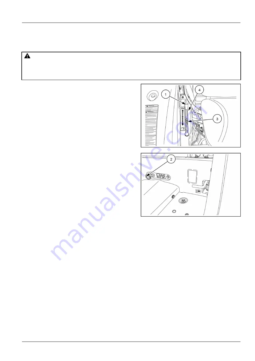
The HPL lever
(1)
is located on the right-hand control pod.
This lever controls the position of the two lift arms.
To lower the lift arms, first make sure the drop rate con-
trol valve
(2)
is open, then move the HPL lever forward. To
raise the lift arms, move the lever rearward. An adjustable
lower stop
(3)
is located in this quadrant for returning the
lever to a preset lowering position of the hitch. An ad-
justable upper HPL control lever height stop
(4)
prevents
the control lever from exceeding the lift limit and causing
the tractor hydraulic system to go over the relief valve set-
ting.
The hydraulic lift system provides accurate, smooth, and
instant hydraulic power for raising a variety of compatible
equipment whenever the engine is running. The system's
position control feature maintains the selected height or
depth of three-point linkage equipment in relation to the
tractor. When the hydraulic lift control lever is moved to a
higher or lower setting in the quadrant, the system repo-
sitions the equipment to a higher or lower position and
maintains the selected position.
NHIL12CT00681AA
1
NHIL12CT00687AA
2
Position control
Position control provides easy, accurate control of the three-point linkage equipment which operated above the ground,
such as sprayers, rakes, mowers etc. It also provides uniform depth when using a blade or similar equipment on
ground level.
When operating in position control, there is a definite relationship between the position of the control lever in the
quadrant and the position of the equipment. The lever must be moved to change the position of the equipment relative
to the tractor. The system will automatically maintain the equipment in the selected position.
3-23
Содержание Workmaster 25 Tier 4B
Страница 74: ...3 CONTROLS AND INSTRUMENTS 3 28 ...
Страница 102: ...4 OPERATING INSTRUCTIONS 5 Engage the park brake 7 and release the brake ped als slowly NHIL12CT00691AA 6 4 28 ...
Страница 110: ...5 TRANSPORT OPERATIONS 5 8 ...
Страница 116: ...6 WORKING OPERATIONS 6 6 ...
Страница 155: ...7 MAINTENANCE NOTE Approximate fluid capacity for the front axle housing is 5 5 l 5 8 US qt 7 39 ...
Страница 158: ...7 MAINTENANCE Valves Check Contact your NEW HOLLAND dealer to schedule this service for your tractor 7 42 ...
Страница 178: ...8 TROUBLESHOOTING 8 6 ...
Страница 187: ...9 SPECIFICATIONS NHIL12CT00862HA 1 9 9 ...
Страница 188: ...9 SPECIFICATIONS 9 10 ...
Страница 190: ...10 ACCESSORIES 10 2 ...


