


58
| Load Balancing | SmartNA-X 1G/10G Modular
SmartNA-X
™
1G/10G User Guide 1.4
©
2015 Network Critical Solutions Limited
Load balancing non-exclusivity
Egress ports for load balanced groups may still be used as destinations for the normal mapping and filtering functions
of SmartNA-X systems. For example, if tools are monitoring a protocol that has separate control and data channels, it is
possible to load balance the data channel traffic across a set of tool ports, but still to replicate all control channel data to all
of those tool ports at the same time.
Load balancing – Best practices and limitations
When using the load balancing feature, we recommend you follow our suggested best practises and take note of the
limitations that apply.
Best practices
The following best practises can be used to produce good results when setting up load balancing on SmartNA-X devices.
• Unless there is a compelling reason, you should restrict load balancing to one or two headers. Any more than two
headers requires considerably more system resources when running.
• If possible, select headers that will vary randomly for the expected traffic. In the majority of cases, two such headers
will provide effective balancing, and in some cases one may be enough. Note that incoming packets with the same
values for all of the headers selected for balancing will always be directed to the same egress port within the load
balanced group.
• If balancing across many ports or if the system has many other maps configured, if possible, use only a single load
balancing header to avoid overloading the system.
• Groups of two or four egress ports will give the most even output and will be the most memory-efficient.
• Where possible, apply filters to the ingress ports to restrict the stream to just those packets required for load balancing.
For example, if you wish to balance on headers below layers 2, that is, the various IP address and port headers, set up a
filter that restricts packets to just those headers.
Limitations
The following limitations apply when using load balancing on SmartNA-X devices.
• Load balancing needs variation in the selected header fields of incoming traffic to work properly. For example, if the
IPv4 source and destination addresses are selected, but all incoming traffic is between the same pair of addresses, the
balancing will not be effective. All packets would be sent to the same tool.
• The balance is only an approximation, even with ideal incoming traffic. In general, it is not guaranteed that each of
n
egress ports will receive exactly 1/
n
of the incoming packets. Some ports may receive 50% more packets than others
in the worst case. However, as long as two or more header fields are selected, a very even spread should be achieved if
the incoming traffic is suitable.
• There is no failsafe or standby capability for tools that fail. If a group balances traffic among, say, four tools and the
link to one tool goes down, those packets will be dropped. You may reconfigure the system to balance across the
remaining three tools, but this is not automatic.
• The system cannot balance traffic from one ingress port using IPv4 and IPv6 address fields together. This mirrors the
existing limitation on applying both IPv4 and IPv6 filters to maps from the same port.
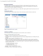
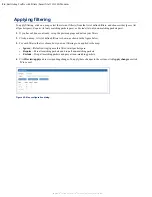
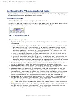
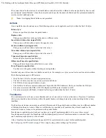
Setting up load balancing
To set up load balancing, map source ports to a Load Balancer group and map the Load Balancer group to destination
ports. Configure the Load Balancer group with the headers that you want to balance against.
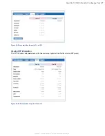
The following example load balances ports
1C
,
1D
,
2C
and
2D
from source ports
3A
and
3B
. It uses the packet's IPv4
source and Layer 4 port source for the load balancing data.
1.
Map port
3A
to
3B
and
3B
to
3A
.