Page 101/ 191
12.2 Location and mounting
The protective capsule must be sited in the vicinity of the bridge on the external deck area of the
vessel to maximize the probability of its survival and recovery following an incident. The capsule
shall be positioned clear of rigging and other potential obstructions
and as near to the centreline
of the ship as practically possible
. Criteria to be considered when assessing the optimum
position shall include but not be limited to the following:
•
Separation from fuel or other potential fire sources.
•
Separation from probable sources of mechanical damage.
•
Operational environment for continued serviceability.
•
Accessibility for copying of recorded data and for routine maintenance.
•
Facilitation of underwater removal and retrieval by both divers and ROVs.
•
There shall be a clear unobstructed space in the vicinity of the capsule to allow an ROV
or diver to work.
•
Compass safe distance = 60 cm.
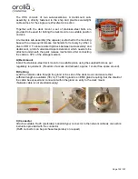
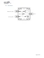
The HSS consists of two sub-assemblies. A deckmount sub-assembly is directly fastened to the
ship and provides watertight cable entries for the single wire WaveNet connection.
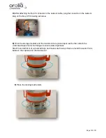
A removable sub-assembly (the capsule) is attached to the mounting base with a unique quick
release mechanism for recovery by either a diver or ROV.
12.3 Power supply
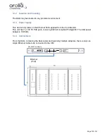
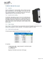
This unit has 1 x 1000 TX PoE port, receiving 802.3af compliant PoE @48V and fully relies on the
Ethernet PoE supplied from the Core Module. The total power budget is 6 Watts.
12.4 Installation and connections
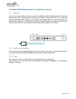
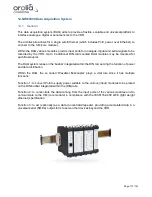
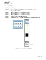
NW-6000 Core Module
Refer to
N6-001.2
Single wire (PoE) ethernet cabling
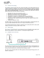
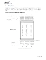
The unit must be connected to any of the VDR Core Module ports (with the optional addition of a
junction box) with a maximum of 100-meter network cable (CAT 6 or higher). It is preferred not to
use any connection between the Core Module and the storage medium.
The unit is to be configured within the VDRs specified (commissioned) IP-range (refer to 2.5
Network configuration).
Содержание NW6000
Страница 1: ......
Страница 91: ...Page 91 191...
Страница 92: ...Page 92 191...
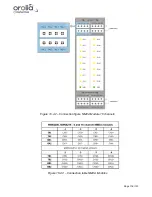
Страница 116: ...Page 116 191 Figure 16 4 2 Connection figure NMEA Module 16 channels Figure 16 4 3 Connection table NMEA Modules...
Страница 120: ...Page 120 191 Figure 17 4 2 Connection figure Digital Module 16 channels...
Страница 121: ...Page 121 191 Figure 17 4 3 Connection figure Digital Module 24 channels...
Страница 125: ...Page 125 191 Figure 18 4 2 Connection figure Analogue Module 8 channels...
Страница 126: ...Page 126 191 Figure 18 4 3 Connection figure Analogue Module 12 channels...
Страница 184: ...Page 184 191 Figure 5 8 1 Sample dataset playback...


