background image

About JBOD

10

2.4. A Tour of the System

These sections show the major components found on the

Netberg Aeon J460 M2 JBOD system.

2.4.1. System

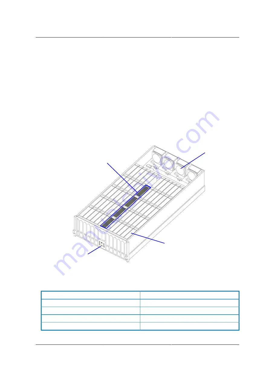
Component Overview

Figure 2.1. System Component Overview

5

4

3

2

1

1


2


3


4

Table 2.2. System Components Overview

Component

1

Internal SAS interface module (x4)

2

Fan module (x4)

3

HDD (x60)

4

Control panel

Содержание Aeon J460 M2 JBOD

Страница 1: ...Netberg Aeon J460 M2 JBOD ...

Страница 2: ...Netberg Aeon J460 M2 JBOD ...

Страница 3: ...3 Hard Disk Drive Assembly 25 3 3 1 Removing a HDD Assembly 25 3 3 2 Installing a HDD Assembly 25 3 4 Power Supply Unit 27 3 4 1 Removing a PSU 27 3 4 2 Installing a PSU 27 3 5 Fan Modules 29 3 5 1 Removing a Fan Module 29 3 5 2 Installing a Fan Module 29 3 6 SAS Interface Modules 31 3 6 1 Removing a SIM 31 3 6 2 Installing a SIM 31 3 7 Internal SAS Interface Modules 33 3 7 1 Removing an ISIM 33 3...

Страница 4: ...er Hazards 54 4 11 Cooling and Airflow 55 4 12 Laser Peripherals or Devices 56 5 Regulatory and Compliance Information 57 5 1 Electromagnetic Compatibility Notices 59 5 1 1 FCC Verification Statement USA 59 5 1 2 Europe CE Declaration of Conformity 59 5 1 3 VCCI Japan 60 5 1 4 KCC Korea 60 5 1 5 Regulated Specified Components 60 5 1 6 Restriction of Hazardous Substances RoHS Compliance 61 5 1 7 En...

Страница 5: ...stallation 24 3 7 Removing HDD Assembly 25 3 8 Installing HDD Assembly 26 3 9 Removing PSU 27 3 10 Installing PSU 28 3 11 Removing Fan Module 29 3 12 Installing Fan Module 30 3 13 Removing SIM 31 3 14 Installing SIM 32 3 15 Removing ISIM 33 3 16 Installing ISIM 34 3 17 Disassembling the Rails 35 3 18 Installing an Inner Rail 36 3 19 Installing Outer Rail 36 3 20 Aligning Rails 37 3 21 Installing C...

Страница 6: ...0 M2 JBOD 7 2 2 System Components Overview 10 2 3 System Front View 11 2 4 Control Panel 12 2 5 System Rear View 14 2 6 SIM Module Features 14 2 7 LED Status 15 2 8 HDD LEDs 17 2 9 ISIM LEDs 18 5 1 Product Regulatory Compliance Markings 57 ...

Страница 7: ...1 Chapter 1 Netberg Aeon J460 M2 JBOD ...

Страница 8: ...s and files Enter type face denotes keyboard keys Warning information appears before the text it references and should not be ignored as the content may prevent damage to the device CAUTIONS APPEAR BEFORE THE TEXT IT REFERENCES SIMILAR TO NOTES AND WARNINGS CAUTIONS HOWEVER APPEAR IN CAPITAL LETTERS AND CONTAIN VITAL HEALTH AND SAFETY INFORMATION Indicates information that is important to know for...

Страница 9: ...AC power cord is unplugged before opening the chassis adding or removing any components Hazardous conditions devices and cables Hazardous electrical conditions may be present on power telephone and communication cables Turn off the server and disconnect the power cord telecommunications systems networks and modems attached to the server before opening it Otherwise personal injury or equipment dama...

Страница 10: ...laims any im plied warranties of merchantability or fitness for any particular purpose Furthermore the manufac turer reserves the right to revise this publication and to make changes from time to time in the con tent hereof without obligation of the manufacturer to notify any person of such revision or changes All the illustrations in this technical guide are for reference only and are subject to ...

Страница 11: ...5 Chapter 2 About JBOD ...

Страница 12: ...stem technicians who are responsible for troubleshooting upgrading and repairing the JBOD chassis This document provides an overview of the hardware features of the system management information and instructions on how to add and replace components of the JBOD ...

Страница 13: ...Drives Hot swap HDD x60 bays Cooling Fans Total 7 1 redundant main fans One built in fan in each power supply unit Power Supply 1400W redundant power supplies 240 VAC Monitoring and Notification LED Indicator Power LED System ID Status LED HDD Active and ID Status LED Internal SAS Interface Module Status LED Firmware Management SCSI enclosure service SES 2 OS Support Windows Linux System Dimension...

Страница 14: ...81 lbs With HDDs fully loaded 85 kg 187 lbs Environmental Operating temperature 5 C to 40 C 41 F to 104 F Humidity 50 to 93 relative humidity Altitude 33 C 3200m Operational Vibration 5 Hz 350 Hz 0 26 Grms Regulations Safety Regulations ...

Страница 15: ...About JBOD 9 2 3 Package content 1 x JBOD storage system 2 x power cord 1 x mini USB cable Rail kit Cable management arm ...

Страница 16: ...r components found on the Netberg Aeon J460 M2 JBOD system 2 4 1 System Component Overview Figure 2 1 System Component Overview 5 4 3 2 1 1 2 3 4 Table 2 2 System Components Overview Component 1 Internal SAS interface module x4 2 Fan module x4 3 HDD x60 4 Control panel ...

Страница 17: ...HDD 29 HDD 30 HDD 31 HDD 32 HDD 33 HDD 34 HDD 35 HDD 36 HDD 37 HDD 38 HDD 39 HDD 40 HDD 41 HDD 42 HDD 43 HDD 44 HDD 45 HDD 46 HDD 47 HDD 48 HDD 49 HDD 50 HDD 51 HDD 52 HDD 53 HDD 54 HDD 55 HDD 56 HDD 57 HDD 59 HDD 59 PSU SIM SIM PSU FAN FAN FAN FAN 1 5 HDDArray1 HDDArray2 HDDArray3 HDDArray4 HDDArray5 5 4 3 2 1 ISIM0 ISIM1 ISIM2 ISIM3 2 4 2 System Front View Figure 2 3 System Front View 5 4 3 2 1 ...

Страница 18: ...2 4 Control Panel 5 4 3 2 1 1 2 3 4 5 6 7 8 9 10 11 12 See the HDD array definition in section Component Placement Table 2 4 Control Panel Icon Item 1 Power button with LED 2 System status LED 3 Fan status LED 4 PSU status LED 5 SIM status LED ...

Страница 19: ...About JBOD 13 Icon Item 6 ISIM status LED 7 ID button with LED 8 1 HDD array 1 LED 9 2 HDD array 2 LED 10 3 HDD array 3 LED 11 4 HDD array 4 LED 12 5 HDD array 5 LED ...

Страница 20: ... 6Gb s S A S CASCADEIN CASCADEOUT HOST 0 HOST 1 HOST 2 HOST 3 1 2 3 Table 2 5 System Rear View Item 1 Fan module x4 2 SIM module x2 3 Power supply unit x2 2 4 5 SIM Module Figure 2 6 SIM Module SERVICE 6Gb s S A S CASCADEIN CASCADEOUT HOST 0 HOST 1 HOST 2 HOST 3 0 1 2 3 1 2 3 4 5 6 7 Table 2 6 SIM Module Features Icon Item 1 MiniSAS port x4 ...

Страница 21: ...ed as follows Table 2 7 LED Status Module Name LED Color Condition Description On System power on System Power Green Off System power off On Enclosure identifi er not identified Identify LED Blue Off Not identified On System fault System Status Amber Off System good On Fan fault Fan Status Amber Off Fan good On PSU fault PSU Status Amber Off PSU good Front Panel En closure SIM Status Amber On SIM ...

Страница 22: ... NOrmal Hot Spare Purple On Hot spare indica tor is turned on Cons Check blue purple blue purple On Consistency check In progress indicator is turned on Hard Drive Tray Rebuild Remap Blue amber blue amber Blink Rebuild remap in dicator is turned on on SPS failed Power Supply Status Amber off SPS healthy on Any fan failure Power Supply Cooling Module Cooling Fans Sta tus Amber off All fans healthy ...

Страница 23: ...s Green Blink Amber On SAS link with ac tivities but physi cal link down on Power on Power Gren off Power off on ISIM fault Status Amber off Power off or dis abled by the other ISIM Blink ISIM identifier ISIM Identity Blue off Normal 2 4 7 HDD LEDs Figure 2 7 HDD Leds HDD Table 2 8 HDD LEDs Icon Item 1 HDD status ID LED 2 HDD activity LED ...

Страница 24: ...About JBOD 18 2 4 8 ISIM LEDs Figure 2 8 SIM Module ISIM Table 2 9 ISIM LEDs Icon Item 1 ISIM ID LED 2 ISIM status LED 3 Power LED ...

Страница 25: ...19 Chapter 3 Install Hardware ...

Страница 26: ... to a power supply can be extreme ly dangerous Follow the guidelines below to avoid personal injury or damage to the server Always disconnect the server from the power outlet whenever you are working inside the server case Wear a grounded wrist strap If none are available discharge any personal static elec tricity by touching the bare metal chassis of the server case or the bare metal body of any ...

Страница 27: ...steps in this section to remove and install the HDD modules 3 2 1 Removing a HDD Module Prerequisite Remove the hard disk assembly See Section 3 3 1 Removing a HDD Assembly 1 Disconnect the interposer card assembly from the HDD assembly 2 Remove the screw s from the HDD module 3 Remove the HDD module from the HDD assembly Figure 3 1 2 5 HDD module removal 1 2 3 2 2 ...

Страница 28: ...Install Hardware 22 Figure 3 2 3 5 HDD module removal 1 2 2 2 2 3 4 Remove the screw from the interposer card 5 Disconnect the card from the assembly bracket Figure 3 3 Disconnecting Interposer Card ...

Страница 29: ...ith the screw hole on card assembly bracket 2 Install the interposer card into the card assembly bracket guiding the connector on card to the slot on bracket 3 Install and secure the screw to the interposer card Figure 3 4 Installing Interposer Card 4 Align the screw holes on HDD module with the screw holes on HDD assembly tray connectors facing outwards 5 Install the HDD module into the HDD assem...

Страница 30: ...Install Hardware 24 Figure 3 5 2 5 HDD module installation 5 6 6 6 7 Figure 3 6 3 5 HDD module installation 7 6 6 6 6 5 ...

Страница 31: ... ALLOW PROPER COOLING OF THE SYSTEM 3 3 1 Removing a HDD Assembly To remove an HDD assembly do as follows 1 Press on the edge of the release latch and pull the latch into the open position To avoid damaging the HDD support the assembly whith the second hand when pulling out of the system 2 Pull the HDD assembly or blank out of the system Figure 3 7 Removing HDD Assembly HDD 1 1 2 3 3 2 Installing ...

Страница 32: ...assembly number marked on the chassis To avoid damaging the HDD support the assembly whith the second hand when in stalling to the system 2 Install the HDD assembly 3 Press down on the release latch until it snaps into place Installing HDD Assembly Figure 3 8 Installing HDD Assembly HDD 2 3 ...

Страница 33: ...the locking latch B lever To avoid damaging the PSU support the module whith the second hand when pulling out of the system 3 Pull the PSU out of the system Figure 3 9 Removing PSU 1 A B 2 3 3 4 2 Installing a PSU To install a PSU do as follows To avoid damaging the PSU support the module whith the second hand when in stalling to the system 1 Insert the PSU into the system Make sure the PSU is flu...

Страница 34: ...Install Hardware 28 Figure 3 10 Installing PSU A B 1 2 ...

Страница 35: ... hold the locking latch B lever To avoid damaging the fan support the module whith the second hand when pulling out of the system 3 Pull the fan module out of the system Figure 3 11 Removing Fan Module A B 1 2 3 3 5 2 Installing a Fan Module To install a fan module do as follows To avoid damaging the fan support the module whith the second hand when installing to the system 1 Insert the fan module...

Страница 36: ...Install Hardware 30 2 Push the fan module handle A down into the closed position Figure 3 12 Installing Fan Module B A 1 2 ...

Страница 37: ...d damaging the SIM support the module whith the second hand when pulling out of the system 2 Hold the latch and pull the SIM out of the system Figure 3 13 Removing SIM SERVICE 6Gb s S A S CASCADEIN CASCADEOUT HOST 0 HOST 1 HOST 2 HOST 3 A 1 1 2 3 6 2 Installing a SIM To install a SIM module do as follows To avoid damaging the SIM support the module whith the second hand when in stalling to the sys...

Страница 38: ...Install Hardware 32 Figure 3 14 Installing SIM SERVICE 6Gb s S A S CASCADEIN CASCADEOUT HOST 0 HOST 1 HOST 2 HOST 3 1 2 ...

Страница 39: ...the handle into the open position To avoid damaging the ISIM support the module whith the second hand when pulling out of the system 2 Hold the handle and pull the ISIM or blank out of the system Figure 3 15 Removing ISIM ISIM 1 1 2 3 7 2 Installing an ISIM To install an ISIM do as follows 1 Position the ISIM LED display facing the corresponding ISIM letter marked on the chassis To avoid damaging ...

Страница 40: ...Install Hardware 34 3 Press down on the ISIM handle until it snaps into place Figure 3 16 Installing ISIM ISIM 2 3 ...

Страница 41: ...tem into a rack install any optional components into the system Stabilize the rack before installing the system if necessary Use caution when removing the inner rail from the rail kit assembly The rails can slide out and cause personal injury or damage to the server Installing the Rails 1 Press the release tab A and remove the inner rail from the rail kit assembly Figure 3 17 Disassembling the Rai...

Страница 42: ...mn 7 Guide the screw s on outer rail through the screw holes on the front cabinet column until the rail clicks in place 8 Extend the rear side of the outer rail to reach the rear cabinet column 9 Guide the screw s on outer rail through the screw holes on the rear cabinet column until the rail clicks in place Figure 3 19 Installing Outer Rail 7 7 8 8 9 9 10 Repeat the previous steps for the other s...

Страница 43: ...e thumb screw s to the system Figure 3 20 Aligning Rails 13 14 14 12 3 8 2 Installing a Cable Management Arm Prerequisite Install the system to the rack cabinet See Section 3 8 1 Installing the Rack Brackets 1 Align the cable management arm with the rear of the chassis 2 On the left side install the outer member of the cable management arm into the rail assem bly 3 On the right side install the in...

Страница 44: ...Figure 3 21 Installing Cable Management Arm 4 3 2 Left Rear Right Right 5 Install the straps as shown Figure 3 22 Straps Rear 6 On the left side install the outer member of the cable management arm into the rail assem bly ...

Страница 45: ...Install Hardware 39 Figure 3 23 Installing Cable Management Arm 2 3 7 Right Rear ...

Страница 46: ...n J460 M2 systems are indexes as 0 1 for counting purposes only Example J460 M2_0 See the following diagram for information on connecting the single server via extrernal miniSAS cable to the Aeon J460 M2 server and the connection from J460_M2_0 to J460_M2_1 system in the following diagram Figure 3 24 One Server Topology_1 JS300_G3_0 JS300_G3_1 ...

Страница 47: ...for counting purposes only Example J460_M2_0 In two server topology the Aeon J460 M2 s SIM ports are divided into two zones Server A con nects to a SIM port via external miniSAS cable in zone 1 and server B in zone 2 See the division by zones and cable connections from the servers A and B to the J460_M2_0 system as well as the connection from J460_M2_0 to J460_M2_1 system in the following diagram ...

Страница 48: ... In four server topology the Aeon J460 M2 s SIM ports are divided into 4 zones Server A connects to a SIM port via external miniSAS cable in zone 1 server B in zone 2 server C in zone 3 and server D in zone 4 See the division by zones and cable connections from the servers A B C and D to the J460_M2_0 in the following diagram Figure 3 27 Four Server Topology JS300_G3_0 ...

Страница 49: ...duct the product documentation takes prece dence Your server should be integrated and serviced only by technically qualified persons You must adhere to the guidelines in this guide and the assembly instructions in your server man uals to ensure and maintain compliance with existing product certifications and approvals Use only the described regulated components specified in this guide Use of other...

Страница 50: ...n the product and or the product packaging Indicates the presence of a hazard that may cause minor personal injury or property damage if the CAUTION is ignored Indicates the presence of a hazard that may result in serious personal injury if the WARNING is ignored Indicates potential hazard if indicated information is ignored Indicates shock hazards that result in serious injury or death if safety ...

Страница 51: ... are required to safely handle the system Restricted Access Location The server is intended for installation only in a Server Room or Com puter Room where both these conditions apply access can only be gained by SERVICE PERSONS or by USERS who have been instructed about the reasons for the restrictions applied to the location and about any precautions that shall be taken and access is through the ...

Страница 52: ...ipment ITE which may be installed in offices schools computer rooms and similar commercial type locations The suitability of this product for other product categories and environments such as medical industrial residential alarm systems and test equipment other than an ITE application may require further evaluation ...

Страница 53: ...k Isolated from strong electromagnetic fields produced by electrical devices In regions that are susceptible to electrical storms we recommend you plug your system into a surge suppressor and disconnect telecommunication lines to your modem during an electrical storm Provided with a properly grounded wall outlet Provided with sufficient space to access the power supply cord s because they serve as...

Страница 54: ...injury or equipment damage Conform to local occupational health and safety requirements when moving and lifting equip ment Use mechanical assistance or other suitable assistance when moving and lifting equipment To reduce the weight for easier handling remove any easily detachable components ...

Страница 55: ... EACH SYSTEM POWER SUPPLY SOME POWER SUPPLIES IN SERVERS USE NEUTRAL POLE FUSING TO AVOID RISK OF SHOCK USE CAUTION WHEN WORKING WITH POWER SUPPLIES THAT USE NEUTRAL POLE FUSING SOME POWER SUPPLIES IN SERVERS USE NEUTRAL POLE FUSING TO AVOID RISK OF SHOCK USE CAUTION WHEN WORKING WITH POWER SUPPLIES THAT USE NEUTRAL POLE FUSING THE POWER SUPPLY IN THIS PRODUCT CONTAINS NO USER SERVICEABLE PARTS DO...

Страница 56: ...e grounded electrical outlets The power cord s must meet the following criteria The power cord must have an electrical rat ing that is greater than that of the electrical current rating marked on the product THE POWER CORD MUST HAVE SAFETY GROUND PIN OR CONTACT THAT IS SUITABLE FOR THE ELECTRICAL OUTLET THE POWER SUPPLY CORD S IS ARE THE MAIN DISCONNECT DEVICE TO AC POWER THE SOCKET OUTLET S MUST ...

Страница 57: ...the power supply There are no serviceable parts in the power sup ply Return to manufacturer for servicing Power down the server and disconnect all power cords before adding or replacing any non hot plug component When replacing a hot plug power supply unplug the power cord to the power supply being replaced before removing the power supply from the server IF THE SERVER HAS BEEN RUNNING ANY INSTALL...

Страница 58: ...ient If installed in a closed or multiunit rack assembly the operating am bient temperature of the rack environment may be greater than room ambient Therefore consid eration should be given to installing the equipment in an environment compatible with the maxi mum ambient temperature Tma specified by the manufacturer Reduced Air Flow Installation of the equipment in a rack should be such that the ...

Страница 59: ...ATIC WRIST STRAP ATTACHED TO CHASSIS GROUND ANY UNPAINTED METAL SURFACE ON YOUR SERVER WHEN HANDLING PARTS Always handle boards carefully They can be extremely sensitive to ESD Hold boards only by their edges After removing a board from its protective wrapper or from the server place the board component side up on a grounded static free surface Use a conductive foam pad if available but not the bo...

Страница 60: ...IF THE BATTERY IS INCORRECTLY REPLACED WHEN REPLACING THE BATTERY USE ONLY THE BATTERY REC OMMENDED BY THE EQUIPMENT MANUFACTURER DISPOSE OF BATTERIES ACCORDING TO LOCAL ORDINANCES AND REGU LATIONS DO NOT ATTEMPT TO RECHARGE A BATTERY DO NOT ATTEMPT TO DISASSEMBLE PUNCTURE OR OTHERWISE DAMAGE A BATTERY ...

Страница 61: ...ATE THE SYSTEM ONLY WITH THE CHASSIS COVERS INSTALLED OPERATING THE SYSTEM WITHOUT THE COVERS IN PLACE CAN DAMAGE SYSTEM PARTS TO INSTALL THE COVERS Check first to make sure you have not left loose tools or parts inside the system Check that cables add in cards and other components are properly installed Attach the covers to the chassis according to the product instructions ...

Страница 62: ...OID RISK OF RADIATION EXPOSURE AND OR PERSONAL INJURY Do not open the enclosure of any laser peripheral or device Laser peripherals or de vices are not serviceable Return to manufacturer for servicing Use certified and rated Laser Class I for Optical Transceiver product ...

Страница 63: ...Marks USA Canada US C CE Mark Europe FCC Marking Class A USA This device complies with Part 15 of the FCC Rules Operation of this device is subject to the following two conditions 1 This device may not cause harmful interference and 2 This device must accept any interference received including interference that may cause undesired operation VCCI Marking Class A Japan BSMI Certifi cation Num ber Cl...

Страница 64: ...ANCE REGION MARKING GOST R Marking Russia ICES Canada This Class A digital apparatus complies with Canadian ICES 003 Cet appareil numérique de la classe A est conforme à la norme NMB 003 du Canada Recycling Package Mark Other than China Corrugated Recycles CFB 40 ...

Страница 65: ...couraged to try to correct the interference by one or more of the following mea sures Reorient or relocate the receiving antenna Increase the separation between the equipment and the receiver Connect the equipment to an outlet on a circuit other than the one to which the receiver is con nected Consult the dealer or an experienced radio TV technician for help Any changes or modifications not expres...

Страница 66: ...ications and or declarations the following regulated components must be used and conditions adhered to Interchanging or use of other component will void the UL listing and other product certifications and approvals Updated product information for configurations can be found on the site at the following URL If you do not have access to the Web address please contact your local representative Add in...

Страница 67: ...based on declaration that materials banned in the RoHS Directive are either 1 below all applicable threshold limits or 2 an approved pending Ro HS exemption applies RoHS implementation details are not fully defined and may change Threshold limits and banned substances are noted below Quantity limit of 0 1 by mass 1000 PPM for Lead Mercury Hexavalent Chromium Polybrominated Biphenyls Diphenyl Ether...

Отзывы: