Checking the General Health of Each of the Modules
Visual Check of CPU Board Power
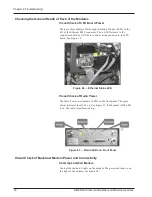
There are three Ethernet Status Light Emitting Diodes (LEDs) to the
left of the Ethernet RJ45 connector. The red LED closest to the
connector should be lit if there is power being supplied to the CPU
board. See Figure 66.
Figure 66 – Ethernet Status LED
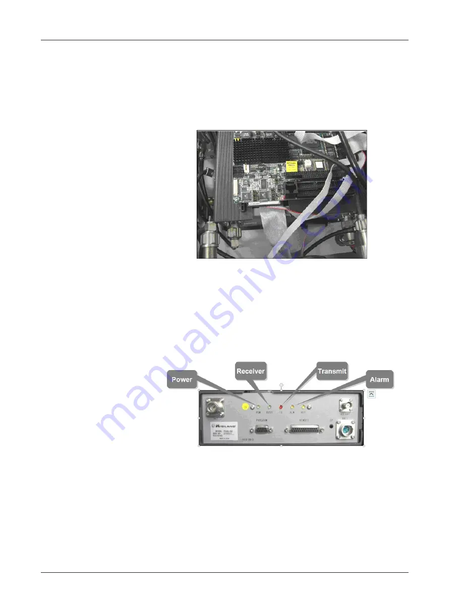
Visual Check of Radio Power
The radio has several indicator LEDs on the front panel. The green
Power indicator should be on. See Figure 67. If the amber ALM LED
is on, the radio is malfunctioning.
Figure 67 – Radio LEDs on Front Panel
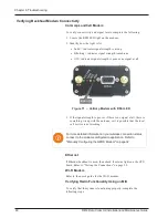
Visual Check of Backhaul Modem Power and Connectivity
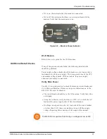
Cal Amp LandCell Modem
Look at the indicator lights on the modem. The power indicator is on
the right of the modem. See Figure 68.
76
R450 Data Collector Installation and Maintenance Guide
Chapter 6: Troubleshooting
Содержание R450
Страница 2: ......
Страница 3: ...R450 Data Collector Installation and Maintenance Guide ...
Страница 8: ...This page intentionally left blank ...
Страница 18: ...This page intentionally left blank xvi R450 Data Collector Installation and Maintenance Guide Tables ...
Страница 20: ...This page intentionally left blank xviii R450 Data Collector Installation and Maintenance Guide Tables ...
Страница 143: ......


