N723-EA Hardware User Guide
Chapter 4 Module Pins
Copyright © Neoway Technology Co., Ltd. All rights reserved.
17
⚫
If you need to use the I2S or RMII function, contact Neoway FAEs.
⚫
Do Not pull-down USB_BOOT before the initialization process is completed.
⚫
All the RESERVED and Ground pins must be left floating.
4.2
Pin Description
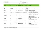
Table 4-1 lists the IO definitions and DC characteristics.
Table 4-1
Pin description
IO type
Pin description
AI
Analog input
AO
Analog output
AIO
Analog input/output
B
Digital Input/Output
DI
Digital Input
DO
Digital Output
PI
Power input
PO
Power output
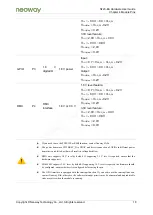
Table 4-2
Level feature
Interface
type
Power
domai
n
Power
domain
description
Power domain
features
Logic level
USIM
P1
USIM
interface
1.8 V/3.0 V self-
adaptive
1.8 V level feature:
IH
DD_P1
DD_P1
0.7 V
~ V
0.2V
V
=
+
IL
DD_P1
0.3V ~ 0.3 V
V
-
=
OH(Min)
DD_P1
0.2V
V
V
-
=
OL(Max)
0.2V
V
=
3.0V level feature:
IH
DD_P1
2.0V ~
0.3V
V
V
=
+
IL
0.3V ~ 0.8
V
-
V
=
OH(Min)
2.4V
V
=
OL(Max)
0.4V
V
=
SD/eMM
C
P2
SD/eMMC
interface
1.8 V or 3.0 V
1.8 V level feature:
IH
DD_P2
DD_P2
0.7 V
~ V
0.2V
V
=
+


