Nozzle down test:If choose left or right mark camera alignment method,this function will turn to gray and not available
to operate.If choose nozzle1-8 alignment method,this function will be black and available to operate.Insert a pick height
value and then click “nozzle down test”to judge whether the setted pick height is reasonable or not.
Point 1,Point 2,Middle point :Use to confirm the IC center coordinate.For example,if choose alignment mthod”left
mark camera”,first select the first pitch center in left-bottom corner,click point 1,then select the second pitch center in
right-top,click point 2,finally click middle point,the machine can calculate out the IC center coordinate.
Light source:outer ring,middle ring,Inner ring,Mark point generally select to use outer or inner ring,select
corresponding light source according to PCB kind.
Brightness:Image recognize brightness can be adjusted on the drop-down list
3.2 PCB angle
PCB angle detect should be under the mode of Single board and manual programming,PCB angle will influence the
accuracy of mounting. The angle closer to 0 degree the better, and the angel deviation need to be within 1 degree. The angle
of PCB is generated according to panelized PCB coordinate, but we can also adjust the angle by manual. Click “Angle
Detect” button, according to the index of machine to choose two points, then a new PCB angle will be generated. (Note, the
two points need to be paralleled)
4. Coordinate information
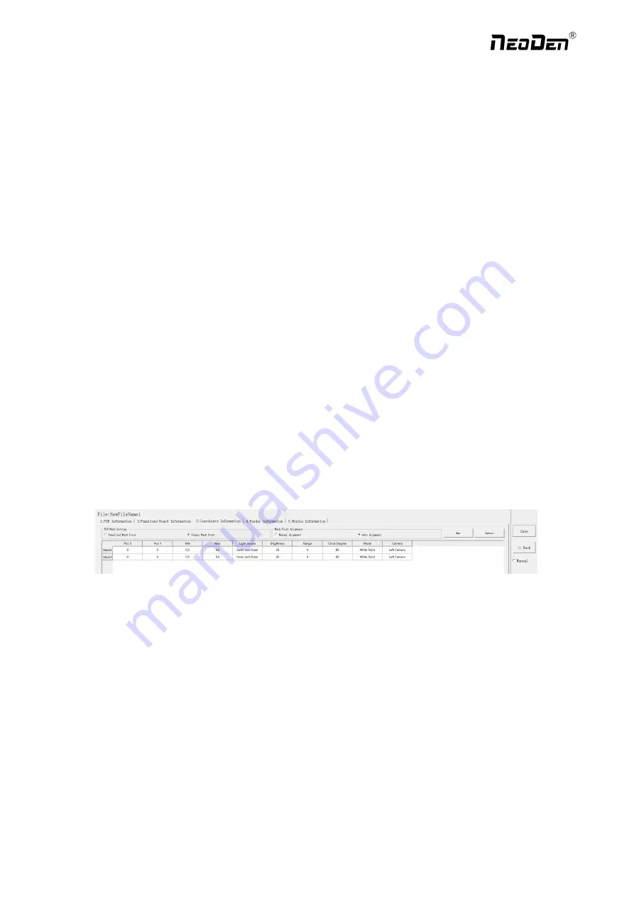
4.1 PCB Mark setting
Function: After finishing mark setting, when the machine is working, the specific position and direction of PCB can confirm
via setting mark. Only in this way the next step of mounting work can carry out.PCB mark setting interface see below fig.
(
1
)
Panelized mark point
It is mainly used for multiple identical PCB boards consistent of the whole board, when place every panel board, the
machine will rescan small panel board’s mark point.
(
2
)
Single mark point
It is mainly used for a single PCB board and multiple identical PCB boards consistent of the whole board (Notice:
coordinate programming is done as a single board)
Generally, need to select 2 or 3 mark points.
4.2 Mark point alignment
Manual alignment:If there is no mark point on the PCB, which can through some location holes and set up some special
reference point manually to replace and confirm reference position. Note:Generally use SMD1 coordinate in chip list and
the one that is relatively easy to find far away from SMD1 as mark points,In this way, the relative placement effect will be
18
Zhejiang
NeoDen Technology Co.,Ltd.
Содержание K1830
Страница 6: ...1 3Working Area Structure Figure 3 Top view of main mounting area 6 Zhejiang NeoDen Technology Co Ltd ...
Страница 7: ...Figure 4 X axis Beam Figure 5 Main Placement Head Camera 7 Zhejiang NeoDen Technology Co Ltd ...
Страница 35: ...8 2 Component Positions Setup 35 Zhejiang NeoDen Technology Co Ltd ...
Страница 44: ...11 Structure and maintenance instruction 11 1 Feeder Brief Introduction 44 Zhejiang NeoDen Technology Co Ltd ...


