CHAPTER 4. OMNI DRIVE MODULE
4.1. PRODUCT DESCRIPTION
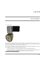
All four wheels must be aligned correctly at all times to avoid jamming or slippage. Please mind that the angle between
the wheels must change according to the movement’s centre of rotation.
4.1.3 Special Features
4.1.3.1 Logic Power Supply
The drive amplifiers of the Omni-Drive-Module feature a separate power supply pin for the internal logic unit. In
case of an emergency stop the main power line can be cut without affecting the internal microcontroller or the motors’
feedback devices.
This means that during emergency stop all important functions of the drives (CAN-communication, position detection,
etc.) are maintained even if the possibly dangerous power is switched off and motions are stopped.
4.1.3.2 Position Switch
An internal inductive position sensor is connected to the amplifier of the orientation drive and can be used for homing.
Due to variances in the assembly process the homing position may slightly differ from module to module. Therefore
the control software must implement an adjustable offset for each orientation drive.
Tip:
Proper functioning of the overall drive system can only be achieved by aligning all wheels correctly at all times.
4.1.3.3 Digital and Analogue I/Os
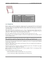
Each drive amplifier provides six digital inputs, two digital outputs and one analogue input. Three digital inputs and
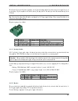
one digital output can be accessed via the PCB’s connectors. Please refer to
(page 53) for details. One of
the inputs is used for the position switch of the orientation drive. Further information about the I/Os can be found on
the Elmo Motion Control homepage at
4.1.3.4 Programming
Each drive amplifier contains an integrated logic capable of running simple user programs. This feature can be used
to shift some basic functions from the main control software to the drive amplifiers. Possible functions are:
• Automatic homing after power on
• Automatic realignment of the drives after emergency stop
• Automatic motor off after a predefined time of inactivity
Details on the programming feature can be found on the Elmo Motion Control homepage.
45
Содержание MMO-700
Страница 1: ...MMO 700 Neobotix GmbH Apr 14 2022 ...
Страница 11: ...CHAPTER 1 MMO 700 1 6 TRANSPORT Fig 3 Position of the auxiliary batteries and battery connectors 7 ...
Страница 33: ...CHAPTER 3 GENERAL HARDWARE INFORMATION 3 4 CHARGING STATIONS Fig 2 Position of the main power switch X 29 ...
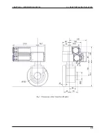
Страница 52: ...CHAPTER 4 OMNI DRIVE MODULE 4 4 ELECTRICAL INSTALLATION Fig 1 Dimensions of the Omni Drive Module 48 ...
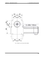
Страница 53: ...CHAPTER 4 OMNI DRIVE MODULE 4 4 ELECTRICAL INSTALLATION Fig 2 Bottom view of the Omni Drive Module 49 ...
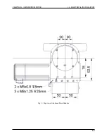
Страница 54: ...CHAPTER 4 OMNI DRIVE MODULE 4 4 ELECTRICAL INSTALLATION Fig 3 Top view of the Omni Drive Module 50 ...

