CHAPTER 3. GENERAL HARDWARE INFORMATION
3.6. SAFETY INSTRUCTIONS
3.6.7.3 Working Area
When choosing and preparing the working area special care has to be taken to ensure both a reliable localisation and
motion control. The robot must never be operated in areas where there are staircases leading down, elevated platforms
or other possibilities for falling or dropping down.
The localisation system of the mobile robot requires clearly visible landmarks and a high quality map of the surround-
ing. Further information on this topic can be found in the documentation of the used software. Please contact Neobotix
in case of any problems.
The motion control system of the mobile robot will only work reliably on an even ground and without slippage. Dirt
like dust, sand, oil or water may cause the wheels to slip and the robot to move uncontrolled. This might even result in
a loss of localisation which might make the robot leave the predefined path and enter prohibited or dangerous areas.
Danger:
The robot must never be operated in areas where it might fall down staircases, loading ramps or similar.
3.6.7.4 Mechanical Overload
The defined maximum payload must not be exceeded. Overloading the robot may lead to reduced life expectancy of
the drives and to damages to the robot. It might also affect the driving properties, resulting in unwanted movements
and might even cause the robot to leave the predefined paths.
3.6.7.5 Electrical Overload
The robot’s on-board power supply must not be overloaded. Extreme overload may lead to overheating, damages to
the electrical installation and to short circuiting.
Please contact Neobotix before modifying the electrical system of the mobile robot.
3.6.7.6 Modifications
The robot must always be turned off and disconnected from all power sources before any modification is carried out.
Working on the robot while it is connected to a power source or turned on results in the risk of electrical shock to the
worker and damages to the robot.
Note:
Additional information on maintenance and hardware modifications can be found at
(page 38).
3.6.8 Configuring the Safety Fields
To achieve both high agility and a safe operation, the safety fields of the laser scanners must be configured and activated
according to the intended motion. Prior to the first operation the safety fields have to be defined with consideration of
the application’s requirements, the working environment and the desired speed. If the safety fields are to be actively
selected instead of being automatically activated, the wiring may need to be changed and a routine to select and activate
the safety fields has to be implemented in the control software.
Warning:
At delivery a set of safety field is defined which will avoid collisions in most situations. These settings
must be tested and, if necessary, be adjusted prior to the first operation. Otherwise the required level of safety
cannot be guaranteed.
36
Содержание MMO-700
Страница 1: ...MMO 700 Neobotix GmbH Apr 14 2022 ...
Страница 11: ...CHAPTER 1 MMO 700 1 6 TRANSPORT Fig 3 Position of the auxiliary batteries and battery connectors 7 ...
Страница 33: ...CHAPTER 3 GENERAL HARDWARE INFORMATION 3 4 CHARGING STATIONS Fig 2 Position of the main power switch X 29 ...
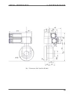
Страница 52: ...CHAPTER 4 OMNI DRIVE MODULE 4 4 ELECTRICAL INSTALLATION Fig 1 Dimensions of the Omni Drive Module 48 ...
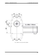
Страница 53: ...CHAPTER 4 OMNI DRIVE MODULE 4 4 ELECTRICAL INSTALLATION Fig 2 Bottom view of the Omni Drive Module 49 ...
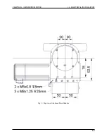
Страница 54: ...CHAPTER 4 OMNI DRIVE MODULE 4 4 ELECTRICAL INSTALLATION Fig 3 Top view of the Omni Drive Module 50 ...

