


Chapter 3 Connectors
43
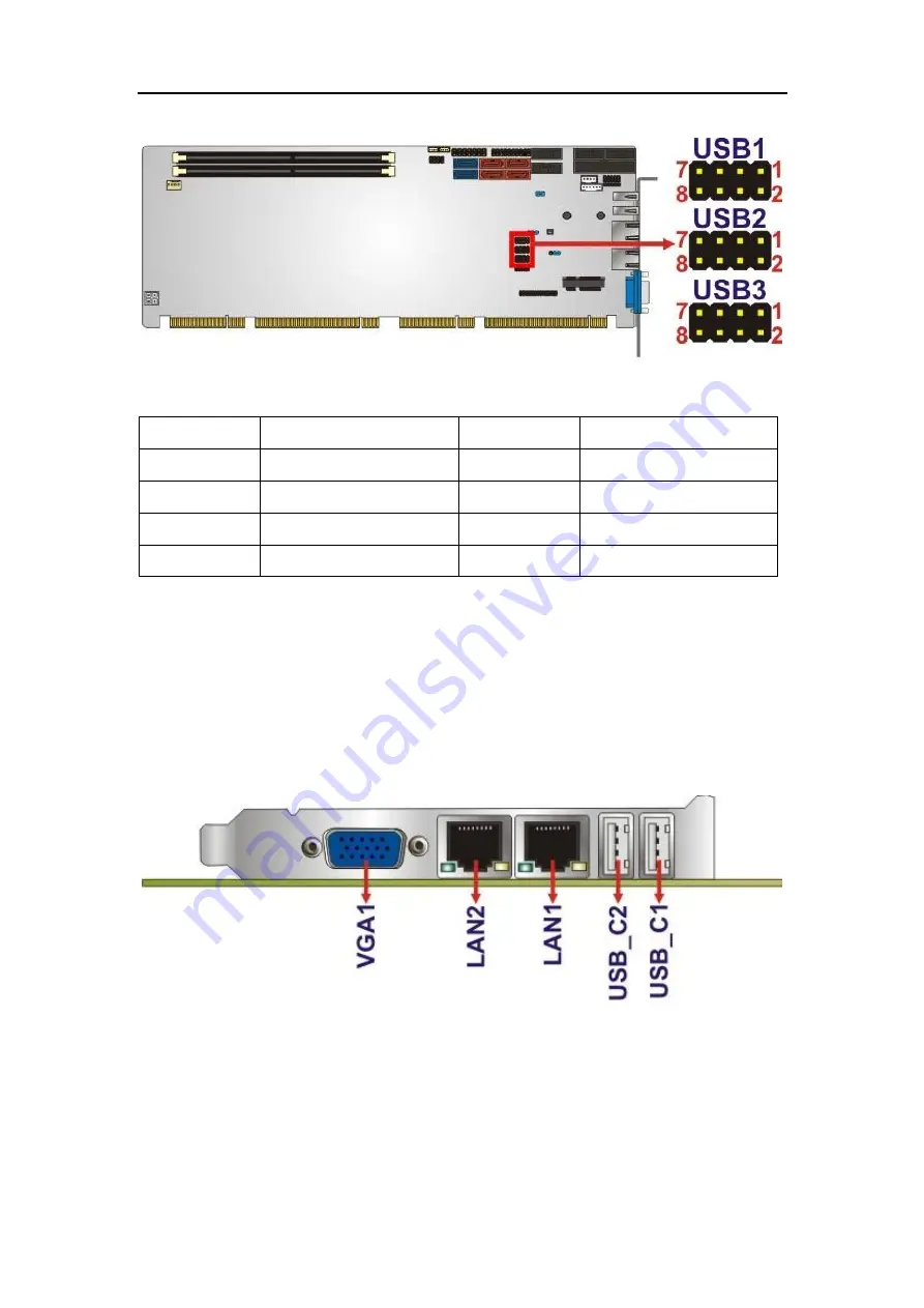
Figure 3-22: USB Connector Pinout Locations
PIN NO.
DESCRIPTION
PIN NO.
DESCRIPTION
1
VCC
2
GND
3
DATA-
4
DATA+
5
DATA+
6
DATA-
7
GND
8
VCC
Table 3-23: USB Port Connector Pinouts
3.3 External Peripheral Interface Connector Panel
The figure below shows the external peripheral interface connector (EPIC)
panel. The EPIC panel consists of the following:
Figure 3-23: External Peripheral Interface Connector
3.3.1
Ethernet Connectors
CN Label:
LAN1
and
LAN2
CN Type:
RJ-45
CN Location:
See
Figure 3-23
CN Pinouts:
See
Figure 3-24
and
Table 3-24


