


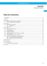


Rail System 920 Touchless
3 Description
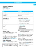
3.1 Technical specifications
3.1.1 Dimensions
See
and
3.2 Technical data
Item
Dimension
Application
Vehicles stationary, at right angles to the rail
Mounting height
Rail 4100 mm (13 ft 6 in) recommended
Pipe diameter
Ø 100 mm (4”)
Weight extraction unit complete
Approximately 35 kg (77.16 lb)
Recommended airflow
Approximately 600 m3/h (356 cfm)
Exhaust temperature
Section 2.2 General safety instructions
• Intermittently maximum 180°C (350°F)
• Continuously maximum 150°C (300°F)
Positioning
• Total vertical movement 2.0 m (6.56 ft)
• Total horizontal reach 1.0 m (3.28 ft)
Recycling material
.
Material
• Suction trolley: Polymer
• Nozzle: EPDM
• Telescopic pipe: Aluminium
4 Installation
4.1 Delivery check
If there are any damaged or missing parts when the
product is delivered, notify the carrier and the local
Nederman representative immediately.
4.2 Rail placement
Before mounting the product, determine the height
and position of the rail in relation to the car lift. It is
very important to decide what vehicle lengths are
.
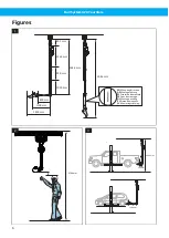
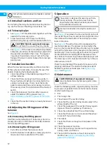
4.3 Vertical placement
See
. The mounting height from the top of the
rail to the floor is 4100 mm. This height allows enough
free room to walk under the arm.
There will not be enough room to walk under
the product if it is mounted at a height of less
than 4100 mm from the floor to the top of the
rail.
If it is not possible to mount the rail at the re-
commended height of 4100 mm it may not be
possible to reach the car nozzle.
4.4 Horizontal placement
. The recommended sideways position for
the rail is A = 300 mm. It is the minimum distance from
the centre of the rail to the back end of the longest
vehicle that is to be used with the unit. B = 1100 mm is
the maximum distance for the shortest vehicle.
Follow the steps below to determine the sideways rail
position for the product.
1 Calculate the distance from the centre of the rail
to the back end of the longest vehicle that is to be
.
2 Based on the rail position calculated in step 1, de-
termine the length of the shortest vehicle that can
.
3 If necessary, adjust the final placement of the rail
so that the maximum number of cars of different
lengths can be used with the unit.
EN
11
Содержание SYSTEM 920
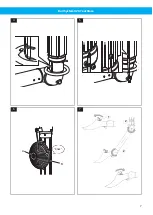
Страница 7: ...Rail System 920 Touchless 4 A B 5 A B Klick 6 2 2 1 7 7...
Страница 8: ...Rail System 920 Touchless A B 8 9 10 11 8...
Страница 44: ...www nederman com...


