Fan Inverter
13 Supervision
It is important to have sufficient airflow in the extraction points. The unit controls the fan capacity to the actual
demand. However, the system pressure may not be sufficient when, for example, too many extractors are open
at the same time, the setpoint has been decreased, or the hose to the pressure tap is damaged.
The unit has an integrated system pressure supervision ability to create an alarm by using an alarm flashlight,
which can be ordered as an accessory. Relay RO2 is assigned for the external signal warning system. See
tion 22.4.4 D4: Control general optional starts
.
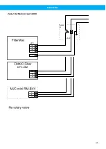
When an alarm flashlight is installed together with FilterMAX, RO1 and RO2 are connected to FilterMax, and the
alarm flashlight is controlled from FilterMAX. See
Section 22.4.6 D6: Control FilterMAX
Note
It is not recommended that supervision be used with pressure loss compensation, see
sure measurement using pressure loss compensation
14 Alarm Flashlight
If an alarm flashlight is connected, the alarm flashlight will flash briefly while Fan Inverter powers up, see
passes the supervision level. The alarm flashlight can also flash during operation if the system pressure drops
below the supervision level, see
Section 14.1 Setting the supervision pressure levels
• Write down the Fan Inverter supervision level in the space below and in the Fan Inverter User Manual:
________________(Pa) Supervision level
Note
If the alarm flashlight continues to flash for approximately 30 seconds after Fan Inverter is started, or if
it flashes continually during operation, there is a problem, see
. To see if the
alarm flashlight is functional, stop and restart Fan Inverter. If the alarm flashlight is connected to Fan In-
verter, it does not flash if there is an input voltage interruption.
14.1 Setting the supervision pressure levels
The parameter Lower limit has to be adjusted according to the reference setpoint ‘Keypad SP1’ that is set in the
‘Control page’, see
See
ing sufficient airflow in the extraction devices. 800 Pa is 11% lower than the setpoint pressure, but as it is in a
square relation to the airflow, then the airflow is only 6% lower at the alarm level.
The relay RO2 is activated after a delay time. Adjust the delay time so there are a few flashes before supervision
level is passed to indicate that the alarm flashlight is functional.
When Fan Inverter is connected to FilterMax and the airflow is low, there is an additional 60 second delay before
a FilterMax alarm is activated. The FilterMax display shows ‘hi EP’. In other words, the external pressure drop is
high as if there had been, for example, a safety filter installed.
If ‘Keypad SP2’ is used, DI3 is activated and set to a lower value than the supervision level, an alarm will be activ-
ated. Supervision is disabled if a constant frequency is used, DI4 is activated.
31
Содержание Fan Inverter
Страница 7: ...Fan Inverter B A 5 OK FUNCT BACK RESET 2 3 1 8 6 7 9 4 5 5 6 7 ...
Страница 12: ...Fan Inverter 15 16 12 ...
Страница 61: ...www nederman com ...


