Fan Inverter
12.3 Pressure loss compensation settings
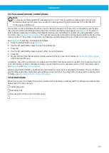
See
. If the measurement point is installed closer to the fan, pressure loss compensation is used.
1
Enable pressure loss compensation with parameter P 3.12.6.1.
2
Open one remote extraction point. Set the required pressure with ‘Keypad SP1’, see
to achieve suf-
ficient airflow.
3
Read the frequency and set this value for ‘Minimum frequency’ in parameter P1.8, see
setup and programming parameters
. The maximum frequency ‘MaxFreq’ is either 50 or 60 Hz.
4
Open the maximum number of extraction points that the system is designed to operate simultaneously. Ad-
just the value for ‘Setpoint 1 maximum compensation’ (P 3.12.6.2) in steps until there is sufficient airflow
from remote extraction points. Check the function and airflow with different numbers of extraction points in
use.
5
If a second set point is used, then repeat this procedure for ‘SetPoint 2 max compensation’ (P3.12.6.4). Use
the same ‘Minimum frequency’ set in P1.8. See also
.
Code
Parameter
Unit
Default
value
Selected
value
ID
Note
P3.12.6.1 Enable setpoint 1
Disabled
1189
Enables pressure loss
compensation for set-
point 1.
0=Disabled
1=Enabled
P3.12.6.2 Setpoint 1 max compens-
ation
Pa
0
1190
Value added proportion-
ally to the frequency.
Setpoint compensa-
tion = Max compens-
ation * (FreqOut- Min-
Freq)/(MaxFreq-Min-
Freq)
P3.12.6.3 Enable setpoint 2
Disabled
1191
See P3.12.6.1
P3.12.6.4 Setpoint 2 max com-
pensation
Pa
0
1192
See P3.12.6.2
12.4 Balancing the general ventilation
The local exhaust ventilation airflow affects the balancing of the general ventilation in the room.
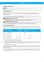
Fan Inverter provides an analogue signal as an input to the general ventilation control system. The analogue
output AO1 at terminals 18 - 19 delivers 0-10V corresponding to 0 - 50Hz (60Hz), or 0-20mA, by changing the
switch for analogue settings.
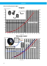
The analogue signal corresponds to the frequency, but it is not linear to the airflow, see
.
To maintain the setpoint pressure at zero airflow, the fan has to run at a certain frequency. When the airflow in-
creases, the frequency will, at low airflow, be constant but will then start increase fairly linearly to the airflow. It
is over this linear part the balancing of the general ventilation is to be made.
In a simple system, a modulating damper 0-10V can be installed and controlled from A01 to reduce the extrac-
tion airflow of the general ventilation system according to the airflow in the local exhaust ventilation.
30
Содержание Fan Inverter
Страница 7: ...Fan Inverter B A 5 OK FUNCT BACK RESET 2 3 1 8 6 7 9 4 5 5 6 7 ...
Страница 12: ...Fan Inverter 15 16 12 ...
Страница 61: ...www nederman com ...

